MUCCRA-CUBE: A 3D DYNAMICALLY RECONFIGURABLE PROCESSOR WITH INDUCTIVE-COUPLING LINK S. Saito, Y. Kohama, Y. Sugimori, Y. Hasegawa, H.Matsutani, T. Sano, K. Kasuga, Y. Yoshida, K. Niitsu, N. Miura, T. Kuroda and H. Amano Faculty of Science and Technology, Keio University 3-14-1 Hiyoshi, Kouhoku-ku, Yokohama 223-8522, Japan
[email protected] Daughter dice
ABSTRACT MuCCRA-Cube is a scalable three dimensional dynamically reconfigurable processor. By stacking multiple dies connected with inductive-coupling links, the number of PE array can be increased so that the required performance is achieved. A prototype chip with 90nm CMOS process consisting of four dies each of which has a 4 × 4 PE array was implemented. The vertical link achieved 7.2Gb/s/chip, and the average execution time is reduced to 31% compared to that using a single chip.
DRP PE array CPU
I/O Memory Memory
I/O Mother chip
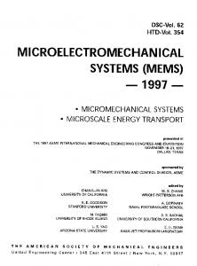
Fig. 1. Building-block 3-D SoCs 1. INTRODUCTION The initial cost of LSI for design and mask development is growing rapidly in advanced technologies. Instead of a single purpose LSI chip with a fixed hardwired logic, flexible reconfigurable architectures are advantageous for multipurpose usage. Multi-core architecture including general purpose CPUs and reconfigurable cores have been developed, and utilized in commercial products[1]. The problem of this type of LSIs is that the performance is limited by the number and size of cores. Since the target applications require various range of performance, series of chips with various number and size of cores must be developed. However, because of the increasing initial cost of LSI, a chip family with plentiful members is difficult to be prepared. SiP (System in Package) or 3-dimensional implementation techniques can address the problem by connecting multiple dies. Various scales and functions can be realized from various combination of dies. Especially, inductive coupling wireless 3-D connection[2, 3, 4, 5] is attractive because of the following properties: (1) Dies can be connected after fabrication, that is, only known-good-dies can be used. (2) The dies can be stacked more than tens so performance can be much increased by adding more numbers of dies. (3) Small daughter dies can be stacked on a part of the mother chip. (4) No special process technology is needed other than standard CMOS process. (5) The communication performance is more than 1GHz with a low energy dissipation and a low bit-error rate (BER< 10−14 ) [5]. By making the best use of the above characteristics, buildingblock 3-D SoCs are feasible. As shown in Fig. 1, a mother chip provides a CPU, a memory module, a reconfigurable core and standard I/Os. Only by using the mother chip,
978-1-4244-3892-1/09/$25.00 ©2009 IEEE
the minimum performance can be obtained. By stacking the daughter dies on a part of die, only required functions can be enhanced. For example, for an application that requires a large memory, memory modules are stacked. When more specific performance is needed, the number of reconfigurable cores can be increased by stacking corresponding daughter dies. By providing a mother die and each daughter die, a family of chips including various types of performance and cost can be prepared. As the first step of such kind of a building-block 3-D SoC, we propose a 3-D dynamically reconfigurable processor called MuCCRA-Cube. By stacking multiple dies, the number of PEs in dynamically reconfigurable processors can be increased. The fundamental technique, an implementation of prototype and performance estimation are introduced. 2. WIRELESS INDUCTIVE COUPLING Interconnection technologies for 3-D ICs are classified into the wired and wireless approaches. Although wired approaches using micro-bumps and through-wafer via have been utilized in real products [6, 3], they are not enough flexible for stacking daughter dies partly on the mother die after fabrication. Wireless approaches are classified into capacitive coupling and inductive one, but the former approach only allows the face-to-face connection so the number of stacked dies is limited to two. Here, we focus on inductive coupling [3, 4, 5] which allows to stack a number of known-good-dies. In addition,
6
Authorized licensed use limited to: University of Washington Libraries. Downloaded on November 10, 2009 at 14:40 from IEEE Xplore. Restrictions apply.
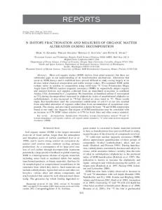
independently. While one SRAM module is used by the PE array, the other can communicate with the outside via 32-bit interface.
RX Die TX
SE 40
Square Coil using metal layer
PE 30
SE 30
Fig. 2. Inductive coupling
PE 20
SE 20
removal, and swapping of dies are also possible after the fabrication of the dies. Recently, techniques on the inductive coupling have been improved, and the contact-less interface without an electrostatic-discharge (ESD) protection device achieves high speed more than 1GHz with a low energy dissipation (0.14pJ per bit) and a low bit-error rate (BER< 10−14 ) [5]. In this approach, an inductor is implemented as a square coil with metal in a common CMOS layout. The data modulated by a driver are transferred between two inductors placed at exactly the same position of two stacked dies, and it is received at the other die by the receiver as shown in Fig 2. This method allows to stack tens of dies if the power consumption of each die is enough low to work without power dissipation facilities. Although more than two inductors can be stacked, multiple transmitters at the same location cannot send the data simultaneously in order to avoid the interference.
PE 10
SE 10
PE 00
SE 00
MEM0
SE 41
SE 31
SE 21
SE 11
SE 01
SE 42
PE 31
PE 32
SE 32
PE 21
PE 22
SE 22
PE 11
PE 12
SE 12
PE 01
MEM1
PE 02
SE 02
MEM2
SE 43
SE 44
PE 33
SE 33
SE 34
PE 23
SE 23
SE 24
PE 13
SE 13
SE 14
PE 03
SE 03
MEM3
SE 04
channel d0,d1 (24bit x 2)
Fig. 3. PE array structure in a die The array structure has the following benefits as a basis of dynamically reconfigurable processors to be stacked: (1) it achieves sufficient performance with a low clock frequency[7], that is, power dissipation problem is not needed to be cared when they are stacked. (2) The 3-dimensional interconnection is a point-to-point link. In this case, the island style network used in MuCCRAs supports enough flexibility to move the data between distant Processing Elements (PEs) in two-dimensional directions.
3. MUCCRA-CUBE 3.1. MuCCRA-Cube in a die
3.1.2. PE structure
3.1.1. PE array structure
Each PE consists of a 24-bit PE Core, connection blocks for the connections to global routing resources and a context memory. The detailed architecture of the PE Core is illustrated in Fig. 4. Since one of the target applications of the MuCCRACube is image processing such as JPEG encoder for embedded systems, in order to treat RGB image data efficiently, the PE Core is designed as a simply structured 24-bit processor. As like common dynamically reconfigurable processors, it is composed of a Shift and Mask Unit (SMU), an Arithmetic and Logic Unit (ALU), and a register file (RFile).
Here, a 3-D dynamically reconfigurable processors called MuCCRA-Cube is developed as the first experience of building block 3-D SoCs. Fig. 3 shows a PE array structure in each die of MuCCRA-Cube. It is composed of a 4 × 4 24bit PE array and four 24-bit distributed memory modules (MEMs) at the bottom edge of the PE array. Like common FPGAs, an island-style interconnection network is used, and it is based on a two-dimensional array of PEs with routing channels located between the rows and columns. Input or output of each PE can connect with channels adjacent to it via a connection block. Data can be transferred along multiple routing channels in any direction, horizontally or vertically by using Switching Elements (SEs) at the channel intersections. The SE is a set of simple programmable switches which can connect to adjacent SEs. It has two 24bit links called (d0, d1) from side to side and up and down. Although it is omitted in the Fig. 3, writing data can be transferred into MEMs via the feedback wires from the uppermost SEs. Each MEM is 24-bit × 256-word and 2-ported SRAM module, and all modules are double-buffered so that operations of the PE array and input/output can be performed
Register File
SMU
MUX
ALU
MUX
zero
MUX
zero
Fig. 4. PE Core Architecture
7
Authorized licensed use limited to: University of Washington Libraries. Downloaded on November 10, 2009 at 14:40 from IEEE Xplore. Restrictions apply.
zero
The SMU supports various types of shift & mask operations and supply of a constant value, and the ALU provides addition/subtraction, multiplication, comparison, and logical operations. The RFile is a 24-bit wide and 8-entry deep register file, and it has a read/write port (A) and a read-only port (B). For avoiding combinatorial loops, an output of the ALU can be connected to an input of the SMU, but the opposite connection is not allowed. On the other hand, each RFile can connect with all of inputs and outputs of the ALU and the SMU. The context memory is a 64-bit × 32-entry memory, and it can hold the configuration data which contains operational instructions of the PE Core and connection instructions to global routing resources. The context memory is read out according to the context pointer from the Context Switching Controller (CSC), and the context switching is done with a clock cycle. In MuCCRA-Cube, the context switching is controlled in each PE array independently. Thus, for parallel processing between PE arrays often requires synchronization between PE-arrays. For this purpose, the CSC provides a handshaking mechanism to wait context switching until the signal from connected PE-arrays satisfies a certain condition. Other context switching mechanisms are the same as other MuCCRA processors[7] and omitted here. Configuration data are loaded to the central configuration data memory, and transferred to context memory for each PE and SE by using RoMultiC[8] multicast scheme. Like previous MuCCRA processors[7], Task Configuration Controller (TCC) manages the loading configuration data from outside the chip and its delivery. The configuration data for the next task can be loaded for the empty space of the context memory during the execution.
Fig. 5. Stacking Method from the die. The stack structure also has a benefit to form an extended datapath without using the long feed back links. As shown in Fig. 6, the computational results from a PE array are transferred to the starting points of datapath formed on the upper stacked PE array through the 3-D interconnection without using long feedback links. redundant data path PE
PE
PE
PE
PE
PE
PE
PE
MEM
MEM
MEM
MEM
PE
PE MEM
PE
PE PE
For inductive-coupling, the inductors for a transmitter and a receiver on adjacent chips should be aligned. In order to stack the PE array with the same structure, we introduced the stacking method shown in Fig. 5. First, an axis of rotation is set at the center of core area (Fig. 5(b)). The even die is then rotated by 180 degrees with respect to the axis of rotation, and stacked. The inductors are placed symmetrically with respect to the axis of rotation, and therefore they remain aligned after the rotation. Due to the symmetry, two links are formed. They are used for an uplink and a downlink. This stacking method also can solve the problem for power supply to intermediate dies. By the rotation, the dies are shifted, which makes spaces for bonding wires to provide power supply. In MuCCRA-Cube, clock signals and the configuration data are transferred to intermediate dies by using these bonding wires in order to make the control of TCC simple. Since clocks delivery cause a certain degree of skew, the data communication between dies are done using dedicated clocks for inductive-coupling channel as described later. The top die exposes all four sides for bonding wires, providing sufficient number of pins for external communications. Thus, the data to be processed are inserted
PE
PE PE
PE
PE PE
(a) 2D
PE MEM
MEM
MEM
3.2. Homogeneous Stacking
PE
MEM
PE
PE
PE
PE
PE
PE
PE PE
PE
PE
PE
PE PE
MEM
PE
PE
PE PE
PE
PE PE PE
PE
PE
MEM
PE
PE
PE
MEM
PE
(b) 3D
Fig. 6. Datapaths using two PE arrays Since only one-way data transfer is supported between two stacked PEs in the method, we assigned a left half part of PEs for communication to the upper direction and the other for the lower direction as shown in Fig. 7. By using the interconnection, the computation starts from the PEs in the bottom left half of the array, and results are transferred to the upper direction. When they reach the upper most PE array, then the computation goes down by using the right half PEs. 3.3. 3-D inductive connection channels In MuCCRA-Cube, three dimensional interconnection is provided for each output of PE as shown in Fig. 8 The 26bits data consisting of 24bits data and 2bits carry are sent from ALU, SMU and RFile through a multiplexer from the PE in
8
Authorized licensed use limited to: University of Washington Libraries. Downloaded on November 10, 2009 at 14:40 from IEEE Xplore. Restrictions apply.
scheme, it is important for all chips to share the phase accurately. A local clock (CLK) is generated on each chip and broadcasted by the clock transmitter to share the phase as shown in Fig. 10 (b). All chips can change the phase at the same time, but inter-chip skew in System Clocks differs the beginning of phase φ0 on each chip. In order to guarantee the timing for data transfer, idle time and time margin are inserted.
Fig. 7. 3-D data direction in MuCCRA-Cube the lower die, and received at the PE in the upper die through the inductive-coupling channels. Fig. 10. Three-phase Interleaving Scheme MUX
Register File
SMU
A block diagram of inductive-coupling interface used in MuCCRA-cube is also shown in Fig. 11. The phase control unit (PCU) consists of a counter and a register file. In every system clock cycle, it initializes the states of transmitting both clock and data, receiving both clock and data or receiving only clock based a 2-bit chip number provided through bonding wires.
ALU
MUX
MUX
MUX
Register File
MUX
MUX
PE
MUX
SMU
ALU MUX
Fig. 8. Connections between PEs Data are transferred serially by using two inductive-coupling channels; TxData and TxCLK. At the rising edge of the clock (PE-CLK) for the sender PE array, TxCLK and TxData start to serial data transfer as shown in Fig. 9. Thus, 2-clock delay is needed for sending 26-bit data through the 3-D connection channels. PE-CLK
Fig. 11. Inductive-coupling interface
TxCLK
According to the state, the transmitters or the receivers are activated. In the transmitting phase, the counter in the PCU counts the number of Oscillator local CLK to match that of data bits to change the phase. Similarly, during the receiving phase, it counts the number of Received Local CLK to match that of data bits. The speed for the TPI is enough to transfer 26bits data serially between PE arrays as to be shown in the evaluation results.
TxData
Fig. 9. Data Transfer in 3-D interconnection
3.4. Three-phase Interleaving Scheme The largest problem for stacking multiple homogeneous arrays is to receive data from a desired transmitter avoiding the crosstalk signals from the other transmitters placed on the same location. In order to address this problem, the three-phase interleaving (TPI) scheme shown in Fig. 10 is introduced. Here, the chip00 transmits to chip01 in phase φ0 , chip01 to chip10 in phase φ1 , and chip10 to chip11 in phase φ2 sequentially as shown in Fig. 10 (a). In the TPI
4. IMPLEMENTATION AND EVALUATION 4.1. Prototype Chip MuCCRA-Cube was implemented with ASPLA’s 90nm CMOS process. Cadence NC-Verilog, Synopsys Design Compiler and Synopsys Astro were used for simulation, synthesis and
9
Authorized licensed use limited to: University of Washington Libraries. Downloaded on November 10, 2009 at 14:40 from IEEE Xplore. Restrictions apply.
layout, respectively. The die size is 2.5mm × 5.0mm, and the PE array works at least 15MHz clock. The frequency can be improved depending on application mapping. Fig. 12 shows the layout of the chip. The central part is occupied with the PE array, and the inductive-coupling links are aligned on its both side for 180 degree rotation. The memory modules are located the left most side. Four chips are stacked as shown in Fig. 13, thus, 64 PEs can work in total.
Table 2. Inductive-coupling Link 1.5GHz Local Clock Bandwidth 7.2Gb/s/chip Energy Consumption 7.6pJ/b Active Si Area 0.031 mm2 Inductor size for Data 100 × 100μm2 Inductor size for Clock 300 × 300μm2 Communication Distance 95μm Chip: 85μm, Glue: 10μm (Thickness)
is achieved in total. In this implementation, since the conservative scale is used, the sizes of coil for data and clock are relatively large, 100μmm2 and 300μmm2 , respectively. On the other hand, the active Si area for link is only 0.031mm2 . Energy consumption of inductive-coupling transceiver and PCU is quite small, 7.6pJ/b. The communication links are confirmed to work with 1.5GHz local clock. Successful operation of TPI is measured and shown in Fig. 14. It demonstrates that each chip generates a local clock (CLK) and broadcasts it to share the phase when each PE array works with 15MHz PE clock.
Fig. 12. Layout of MuCCRA-Cube
Fig. 13. Stacked chips Table 1 shows the breakdown of PE array. Compared with previous MuCCRAs, the ratio of the TCC is increased for storing additional configuration data bits for controlling 3-D interconnection. The PE array area occupies 53.83% of total chip area. Table 1. The breakdown of MuCCRA-Cube chip area Module Area Num Total Ratio [μm2 ] [μm2 ] [%] PE 39538.9 16 632622.6 24.87 SE 13047.3 25 326181.2 12.82 TCC 146456.5 1 146456.5 5.76 CSC 8937.8 1 8937.8 0.35 MEM 62835.8 4 251343.2 9.88 etc 3921.7 3921.7 0.15 Total 1369463.0 53.83
Fig. 14. Measured waveforms of three-phase interleaving
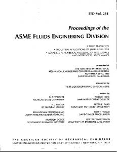
4.3. Execution performance Three applications; Discrete Cosine Transform used in JPEG (DCT), a secure hash algorithm for encryption (SHA-1) and Discrete Wavelet Transform (DWT) for JPEG2000 are implemented using BlackDiamond[9] retargetable compiler. In DCT, the target image block is divided into the number of stacked PE arrays, and executed in parallel. The transformation of the matrix is done by making the best use of 3-D data transfer. In DWT, the total job is divided into two or four tasks and executed with each PE array in the pipelined manner. In SHA-1, iterative execution process is divided
4.2. Communication Link Table 2 shows the specification of inductive-coupling links. The maximum frequency is 1.5GHz and 7.2Gb/s bandwidth
10
Authorized licensed use limited to: University of Washington Libraries. Downloaded on November 10, 2009 at 14:40 from IEEE Xplore. Restrictions apply.
coupling link achieved 7.2Gb/s/chip total bandwidth. However, there found a problem on the layout of boundary of inductive-coupling link area and PE area. This comes from that the lack of our layout technique for combining the handmade full custom cells and standard cells placed and routed automatically. We are now planning to implement bug-fixed version of the prototype by using 65nm CMOS process. Also, the development of tools for 3-D implementation and algorithms dedicated for the architecture is our future work.
1
0.5
Acknowledgments: This work is supported in part by Japan Science and Technology Agency(JST). The authors thank to VLSI Design and Education Centor (VDEC).
0.25
6. REFERENCES
ROW
ROW
TRANS
TRANS
0
ROW
0.75
TRANS
Normalized Execution Time
into the number of PE arrays, and streaming processing is done. Fig. 15 shows the normalized execution time estimated by RTL simulation. Although two clocks delay is needed to transfer between PE arrays, the execution time can be reduced by using multiple PE arrays.
1
2
4
1
2
DCT
4
1
DWT
2
[1] Masato Motomura , “C-based Programmable-HW Core ”STP Engine”: Current Status and Future ,” in IECE Technical Report, RECONF2008-48, 2008.
4
SHA-1
[2] K. Kanda, D. D. Antono, K. Ishida, H. Kawaguchi, T. Kuroda, and T. Sakurai, “1.27-Gbps/pin, 3mW/pin Wireless Superconnect (WSC) Interface Scheme,” in Proceedings of the International Solid-State Circuits Conference (ISSCC’03), Feb. 2003, pp. 186–187.
Fig. 15. Simulated Performance of MuCCRA-Cube In DWT, the synchronization overhead between PE arrays for pipelined operation degrades the performance improvement especially when the number of PEs is two. Fig. 16 shows the utilization ratio which is computed with the following equation:
3D Communication Utilizeation [%]
Util.Ratio =
Data amount to 3D direction × 100 Exec. cycles × 16 Ch/Plane
[3] W. R. Davis, J. Wilson, S. Mick, J. Xu, H. Hua, C. Mineo, A. M. Sule, M. Steer, and P. D. Franzon, “Demystifying 3D ICs: The Pros and Cons of Going Vertical,” IEEE Design and Test of Computers, vol. 22, no. 6, pp. 498–510, Nov. 2005. [4] N. Miura, D. Mizoguchi, M. Inoue, K. Niitsu, Y. Nakagawa, M. Tago, M. Fukaishi, T. Sakurai, and T. Kuroda, “A 1Tb/s 3W Inductive-Coupling Transceiver for Inter-Chip Clock and Data Link,” in Proceedings of the International Solid-State Circuits Conference (ISSCC’06), Feb. 2006, pp. 424–425.
(1)
15
[5] N. Miura, H. Ishikuro, T. Sakurai, and T. Kuroda, “A 0.14pJ/b Inductive-Coupling Inter-Chip Data Transceiver with Digitally-Controlled Precise Pulse Shaping,” in Proceedings of the International Solid-State Circuits Conference (ISSCC’07), Feb. 2007, pp. 358–359.
10
5
0
2
4
DCT
2
4
DWT
2
[6] J. Burns, L. McIlrath, C. Keast, C. Lewis, A. Loomis, K. Warner, and P. Wyatt, “Three-Dimensional Integrated Circuits for Low-Power High-Bandwidth Systems on a Chip,” in Proceedings of the International Solid-State Circuits Conference (ISSCC’01), Feb. 2001, pp. 268–269.
4
SHA-1
Fig. 16. The util. ratio of 3-D channels[%]
[7] H.Amano, Y.Hasegawa, S.Tsutsumi, T.Nakamura, T.Nishimura, V.Tanbunheng, A.Parimala, T.Sano, M.Kato, “MuCCRA chips: Configurable dynamically-reconfigurable processors,” in Proc. of the ASSCC ’07, Nov. 2007.
As shown in Fig. 16, the utilization ratio is not so high in applications implemented here. Especially, in SHA-1, pipelined operation only requires a single results between two neighboring PE arrays, thus the total amount of data exchange is small. Here, we implemented applications so as to minimize the amount of 3-D communications, since algorithm is originally designed for 2-D array. The algorithm considering 3-D array implementation should be tried for making the best use of wide bandwidth for 3-D direction.
[8] V.Tunbunheng, M.Suzuki, H.Amano, “RoMultiC: Fast and Simple Configuration Data Multicasting Scheme for Coarse Grain Reconfigurable Devices,” in Proc. of ICFPT, Dec. 2005, pp. 129–136. [9] V. Tunbunheng and H. Amano, “ DisCounT: Disable Configuration Technique for Representing Register and Reducing Configuration Bits in Dynamically Reconfigurable Architecture,” in Proc. of SASIMI 2007, Oct. 2007.
5. CONCLUSION In the first prototype of MuCCRA-Cube, the operation of inductive links and PE array has been verified. The inductive-
11
Authorized licensed use limited to: University of Washington Libraries. Downloaded on November 10, 2009 at 14:40 from IEEE Xplore. Restrictions apply.