Multi-Agent Systems Implementation and Testing G. Caire1, M. Cossentino2, A. Negri3, A. Poggi3, P. Turci3 1
TILab, Torino, Italy
[email protected] 2
Istituto di Calcolo e Reti ad Alte Prestazioni (ICAR) Consiglio Nazionale delle Ricerche (CNR)
[email protected]
3
Dipartimento di Ingegneria dell’Informazione, Università degli Studi di Parma Parco Area delle Scienze 181A, 43100 Parma, Italy +39 0521 905708 {negri,poggi,turci}@ce.unipr.it
Abstract The need of software tools for designing and testing complex distributed multi-agent systems is considerable. Over the past few years we have been developing a theoretical and practical methodology for designing, implementing and testing multi-agent systems. As part of this effort an agent-oriented CASE tool, which aims at simplifying the multi-agent system designer’s work, and a testing framework, which provides a uniform and automated approach to the testing of multi-agent systems, have been designed and implemented. The aim of this paper is to give an overview of that work with particular attention to the recent results achieved. Therefore the paper mainly focuses on the testing tool and the issues connected with the diagrammatic notations, which should support developers when moving from the design phase towards the implementation phase of multi-agent systems.
1 Introduction Computer science has been and, more than ever, it is still a discipline characterized by a rapid evolution, which enforces software developers and software houses to carry out radical changes, involving mainly the conceptual and methodological point of view. The agent-oriented paradigm can be considered as the result of this evolving process, due to the ever-increasing software complexity. Nowadays, software agents are undoubtedly more than a promising approach to complex software development. During the last twenty years a lot of research work has been undertaken, ranging from theoretical foundations to concrete tools and technologies and application case studies [3]. But in spite of this effort the proposed modelling languages and methodologies still remain incomplete or at least they are not able to fully capture and/or communicate the underlying meaning and complexity of multi-agent systems (MASs) . In particular, up to now, the study of issues connected with the MAS implementation phase has not been stressed enough. Over the past few years we have been directing our research towards the development of a theoretical and practical methodology (PASSI,[5]) for designing, implementing and testing MASs. As part of this effort, an agent-oriented CASE tool, which aims at simplifying the MAS designer’s work, increasing the reuse of code through a database of agents/tasks patterns, and a testing framework, which provides a coordinated and automated approach to the testing of MASs, have been designed and implemented. The aim of this paper is to give an overview of the work done so far, focusing in particular on the latest results achieved. Four main research lines characterize our work: the diagrammatic notations which should support
developers when moving from the design phase towards the implementation phase of MASs [4], the pattern reuse [7], the deployment of MASs [10]and the testing activities. The implementation phase typically needs a very precisely defined model, which fully refines previous design models to achieve a specification that is unambiguous enough to be fed to automated tools such as compilers and code generators. Producing such a detailed model generally entails matching the conceptual entities, gathered from analysis and architectural design deliverables, to the actual technological artefacts that are going to be used to build the system. Applying the above consideration to the case of MASs development, we have to recognize that with the current state of the technology the final implementation of a MAS will most likely use object-oriented technology. In the past years several libraries, frameworks and middleware platforms have been made available, that provide MAS application developers with agent-level abstractions implemented with object-oriented languages and tools [2][11]. When adopting such support systems, developers express interaction, coordination and deliberation concerns through an agent-level API, resorting to plain object orientation when specifying ordinary computation tasks. In our previous works we tried to define a two-dimensional plane and a point on that plane where a diagram showing implementation-level MAS interactions should be placed [4]. In this paper we will go further presenting a diagram, logical consequence of the previous ones, for the multi-level representation of the agent behaviours. The support of a testing tool in the implementation phase can be determinant in cutting down the time and cost of developing the MASs and to guarantee quality assurance. Our aim is not to provide an exhaustive testing tool but to propose a new approach based on a simple testing framework which lets developers build a test suite effortlessly in a cheaply and incrementally way. The framework aims at supporting the developer in creating and executing tests in a uniform and automatic way. In a uniform way because all tests follow the same pattern of execution and produce results in a similar format (binary format) and so alleviate the work to be done by the developer. In an automatic way since all tests do not require user intervention neither during execution nor to detect whether the test has passed or failed. This approach is not new. The need for a framework to support the development of automated binary tests was perceived years ago by the object oriented community and it has led to the emergence of the XUnit testing frameworks. The founder of this family was JUnit [9], a regression testing framework written by Erich Gamma and Kent Beck. Our framework is catalyzed by that project and basing it on the “pay as you go” design bias it proposes itself as an agent-oriented testing framework. It is built on top of JADE and so it allows us to create tests for multi-agent systems based on JADE. The next section describes the diagrams for the multi-level representation of agent behaviours, which will drive the implementation phase, giving useful information concerning the implementation of the interactions between agents and their relationship with the internal structure of a single agent. In particular the first subsection deals with the rationale of the chosen perspective and in the second subsection the new diagrams will be discussed, applying them to a real-world application. Section three introduces our two-levels (agent and society) approach to testing and its relationship to the diagrams of the previous section. Section four describes the implemented framework. More precisely, the first subsection deals with the architecture of the framework, while the second subsection highlights the interesting features of the framework graphical interface. Finally, the fifth section concludes with a discussion about implementation issues and future work.
2 Agent Behavioural Representation: a Step Forward The scope of this section is to introduce an update in the behavioural representation of agents at the implementation level in PASSI. Up to date, two different abstractions were provided: the multiagent (MABD, Multi-Agent Behaviour Description) and the single-agent (SABD, Single-Agent
Behaviour Description). In the first one, the entire agent society is represented using an activity diagram. In this diagram, one swimlane is introduced for each agent and for each task. Activities inside swimlanes indicate portions of behaviour at the class method level of granularity. In several different experiments, this diagram proved very useful both in analyzing the flow of control of different agents (allowing the evaluation of separate, concurrent tasks) and in testing their interactions (see section 3). At the single agent level of abstraction, PASSI prescribes the design of the implementation details of methods (dealing for example with algorithmic issues). These are often provided in terms of activity diagrams or finite-state machines. Both the levels of behaviour descriptions (MABD and SABD) are completed by structural diagrams (class diagrams) at correspondent granularity. The described situation proved to have some limits when dealing with very large systems since the dimension of the MABD diagram could increase beyond any reasonable limit. To encompass this situation we will now propose an extension to this representation that allows the design of very large systems and that also proves to be useful in order to facilitate testing.
2.1 Extending UML Activity Diagram: Rationale of the Choice Representing the dynamics of a MAS is quite different from describing the flow of control of an object-oriented system; the first determinant difference is in the greater encapsulation of the agents; in fact despite having a very complex inner structure (they are often composed of several classes), they interact with the remaining part of the system as a whole (the agent). Another important issue is that agents, usually, cannot directly relate to each others but they need a message transport service that in many architectures is provided by the middleware. These interactions are obviously totally different in nature by the direct method invocations that could take place within the agent among the classes that constitutes it. We decided to support the AUML [1][8] initiative and therefore we mainly consider UML diagrams as the source for our notations. In order to describe the agent interactions, we should choose a diagram that allows the description of the behaviour of the component dimension during time also in terms of the interconnection dimension. This overall requisite can be decomposed in some specific needs: − Being focused on the implementation issues, we aim at obtaining a high level of detail. This sometimes produces very crowded diagrams that going deeply into the particulars fail in providing the designer with a global description of the situation; in the solution we will provide a zoom capability that allows the representation of different levels of details in the same diagram for different agents. − Both agents and objects should be described (if necessary) in the same diagram in order to represent not only the agent but also its internal classes (this structure is essentially OO) and the interactions of the MAS with external not agent-based systems; − Possible interactions that should be described are the communications among different agents (inter-agents relationships) and the classical object-oriented interactions within a single agent (intra-agent relationships). A good solution to these problems could come from the use of UML activity diagrams with some minor extensions of their syntax. These diagrams allow the description of both the structural and behavioural aspects of the MAS; in fact, concepts like swimlanes show the relationships among the software entity related to that swimlane and its dynamical representation in terms of activities/actions. In activity diagrams, time constraints can be explicitly represented (this allows for example the representation of real-time situations) just like concurrency (useful in order to explicitly model agent pro-activeness) and other control-flow structures like branches, forks and joints.
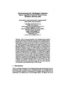
2.2 Multi-level Representation of Agent Behaviours To discuss the new diagrams, we will report an example from an application built to support the production and supply chains of a manufacturing company. This is not a theoretic exercise because the introduction of this software in the real productive environment is ongoing. Because of the large dimension of the whole application we will here describe only a part of it and specifically, we will focus on the interaction among the machine tools and the resulting products of the manufacturing chain. Each product is embodied by an agent that takes the responsibility of contacting the different tools of the plant in order to schedule and receive the manufactures it needs to move from the initial raw material state to the final artefact configuration. Our proposal consists in maintaining the key aspects of the MABD that proved useful in our previous experiences: 1) method level of granularity in describing the pieces of behaviour; 2) representation of the flow of control and the communication exchanged among agents (down to the single message specification) 3) description of the major decisions made by agents. This is simpler using state-machine agents but it is also possible to represent some situations for non deterministic agents The final result of our work is a MAZBD (Multi-Agent Zoomable Behaviour Description) diagram whose resolution could vary from the agent and behaviour to the method level of abstraction. It should be noticed that this diagram is very near to the real implementation of the agent and therefore its elements have a direct counterpart in the actual software solution. Product
MachineTool MachineTool
conv1
P roduct
[ManufactRqst, RDF, ContractNet]
MachineTool. P rodtP haseContract_P artpt
MachineTool. NewP roductionBegin
P roduct. P lanner P lan
MachineTool. Manufacturing [ P roductQueueEmpty ] [ P roductionCompleted ]
P roductDone
done P roduct. P rodtP haseContract_Init
MachineTool. P roductionP haseComplt
[ Not P roductQueueEmpty ]
Figure 1 - The most compact MAZBD configuration
In Figure 1 we can see the highest level configuration of the proposed MAZBD. Two different swimlanes represent the two involved agents (Product and MachineTool). The first performs an initial planning of the manufactures it needs and then contacts a MachineTool in order to ask for some kind of working. This is done with a contract net communication (in our real implementation we used a specifically defined variant of the iterated contract net, but in this work we preferred to simplify the interaction). The MachineTool agent performs the requested working on the products in its list and when a specific production phase is completed starts the operations on the following product. The previous reported diagram is useful in providing a concise view of the overall system behavior and the agent interactions. In the specific case it is easy to catch the initial Product planning activity, the contract phase among the two agents and the working phase done by the MachineTool
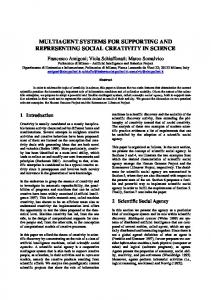
agent. All the reported elements are someway near to the final code implementation since they represent the behaviour expressed by class-level elements of each agent (for example the Product activity stands for the main class of the Product agent, while the Product.Planner activity represents what is to be done by the homonymous behaviour class of that agent). This diagram fails in supporting a detailed analysis of the single agent performed in order to tune its behaviour or detail some fault. To solve this problem we can zoom the description level of the diagram for each specific agent obtaining a granularity that is comparable to the old MABD representation but it is enriched of some new notations. In Figure 2 we can see an expanded version of the previous diagram that offers a full detailed view of the Product agent. In this diagram, each swimlane collects activities performed by a class of the agent (the agent base class or one of the agent's behaviours); each activity represents a method-level element of the agent implementation. The diagram first swimlane is related to the Product agent base class and it reports the initial constructor activity with the following setup method (automatically invoked by most of FIPAcompliant platforms). This latter calls a registration to the Directory Facilitator action and instantiates a new behaviour (Product.Planner) whose duty is to plan the workings to be required to the different machine tools. Until some work is requested this behaviour starts a new communication that contracts the manufacturing, asking to become part of a MachineTool scheduling, thus moving towards some goals in terms of delivery date for the final product. Product
Product.ProdtPhaseContract Init
Product.Planner
MachineTool M achineTool
Product. Product
Product. setup
Product. register_to_df
Product.Planner. Planner
Product.ProdtPhaseContract_Init. ProdtPhaseContract_Init
newBehavior
Product.ProdtPhaseContract_Init. action
Product.Planner. action
Product.ProdtPhaseContract _Init. sendcfp
Product.Planner. PhasePlanner
[ Not ProductionCompleted ] / New Behavior Product.Planner. PlanM anager
M sg1 : ProductRqstConv [ManufactRqst, RDF, ContractNet, cfp]
M achineTool. ProdtPhaseContract_Partpt
M sg2 : ProductRqstConv [ManufactRqst, RDF, ContractNet, propose]
M sg3 : ProductRqstConv [ManufactRqst, RDF, ContractNet, accept]
Product.ProdtPhaseContract_Init. handlePropose
M achineTool. M anufacturing
[ ProductQueueEmpty ]
ProposalEvaluationResult( Accept )
[ ProductionCompleted ]
M achineTool. NewProductionBegin
Product.ProdtPhaseContract_Init. sendAccept
M achineTool. ProductionPhaseComplt
done
ProdtPhaseContract_Init. handleInform
SendM sg
M sg4 : ProductRqstConv [ManufactRqst, RDF, ContractNet, inform-done]
Figure 2 - The MAZBD diagram with the Product agent expanded
It should be noted that while the entire communication was reported in the high level diagram of Figure 1, now in this more detailed representation, all the messages are shown (some are here neglected because of space concerns). Each message is described in term of: − Ontology: the piece of ontology addressed during the communication (ManufactRqst); − Content Language: the content language used in the communication (RDF); − Agent Interaction Protocol (AIP): each communication is supposed to refer to one interaction protocol, in this case we adopted the ContractNet; − Performative: each AIP describes the use of several different performatives (or speech acts) according to the communication status. In Figure 1 we reported messages associated with only a part of the performatives (cfp, propose, accept, inform-done) of the ContractNet AIP and in the shown design we decided to use one different method in order to deal with each of these messages. The reason of this choice is in the wide reuse of patterns that we usually try to pursue. Patterns are supported by PTK (Passi ToolKit, the Rational Rose add-in supporting the design
phase with PASSI) and their structure as regards communication is very similar to the behaviour described in this swimlane [7].
3 A Multi-level Approach to MAS Testing The importance of verifying the accuracy and reliability of software has been universally recognized. Concerning multi-agent systems very few research works have been undertaken in order to provide developers with valuable tools supporting testing activities. Moreover these works are still at very early stage. Actually formal methodologies give validation tests that are however applicable in very few and quite irrelevant cases. The main reason of this lack is that the activities, which should assure that the program performs satisfactorily, are very challenging and expensive since it is quite complicated to automate them. Testing activity in PASSI has been divided into two different steps: the agent test and the society test. The first one is devoted to verify the behaviour of each agent with regards to the system requirements that are under the responsibility of that agent. During the society test, the validation of the overall results of the different agents it is carried on and the successful integration of the different agents is verified. In this paper we will particularly deal with the first category (agent test) and in the following sub-section we are going to discuss our specific approach and the tools that support it. Just in order to provide a quick idea of our strategy in the society test we could note that agent society testing is a kind of integration testing and the integration strategy depends on the agent system architecture where agents dependencies are usually in terms of communications (but sometimes environment mediated interactions could be present). In the case of a multi-layer (open or closed) architecture, it is possible to adopt common strategies like the top-down or bottom-up composition rules (for example with an holonic MAS [12]). With other MAS configurations the integration problem becomes much more difficult to solve because the proactive nature of agents, in some cases, does not allow the identification of subset of agents that could be tested alone. Such situations should be faced with a study of the agent responsibilities (in terms of functionalities provided) and ontology (an agent is not expected to interact with something that is out of its knowledge). Society test for mobile agents is also influenced by many configuration management and hosting platform capabilities problems that can effect the agent/system functionality or performance. In the case of functionality, it is not easy for an agent implemented with most diffused platforms to verify before moving to a specific host if all the (not standard) libraries that it needs are available; as regards performance it is easy to imagine the problem that an agent dealing with a great amount of multimedia data could face when moving to an host that cannot provide enough resources (elaboration power, network bandwith and so on) to it.
3.1 Agent Level Testing In this sub-section we will show the strong relationship that exists between the previous discussed multi-level representation and the agent test. This latter is essentially composed of two different levels of activities. First of all the black box behaviour of the agent should be considered. In most common cases, an agent interacts with the remaining part of the system using communications. Testing its behaviour corresponds to begin an interaction and evaluating its result. We usually perform this test using a driver/stub agent when the agent under test is supposed to be a participant/initiator in the communication. The construction of these driver/stub agents is easily performed with the Agent Factory tool [6] that allows the composition of an agent starting from a repository of patterns (behaviours related to the implementation of most common FIPA standard interaction protocols are all part of these). The specification of the result to be expected from communication acts (a series of messages) can
be derived from the study of the discussed MAZBD diagram at the agent level of detail. This proves also useful when testing agents interacting with external actors (for example via a GUI) while the diagram could not be sufficient when agents interact with the environment (using sensors or actuators). In this case, more information should be extracted from other parts of the design. The second level of agent test is devoted to testing the agent internal behaviours and it can be thought as a white box testing of the agent structure (it is known to the test case designer how behaviours are related and their flow of control) where each single behaviour is seen as a black box. The result is therefore a kind of black box testing of a subsystem (the agent composed of the agent base class and several behaviour classes). Again we use the MAZBD diagram to deduct the test cases to be applied. This time the proper detail level is the most detailed one (see Figure 2). In this configuration, it is easy to explore the flow of control among the different agent components and to elaborate the test strategy. The next section describes the tool we use to perform the agent tests when the agent is implemented with the JADE platform.
4 The Testing Framework Our aim is not to provide an exhaustive testing tool but to propose a new approach based on a simple testing framework which lets developers build a test suite effortlessly in a cheaply and incrementally way. As a framework, it provides a unifying application model and a partial implementation of it, trying to support the developer in creating and executing tests in a uniform and automatic way. We are convinced that our approach to testing provides developers with a framework that reduces considerably the time needed for creating new tests and analysing the results. Indeed, the uniformity of the approach and the binary presentation of the results are in our opinion the key for a testing framework to be successful. Firstly because the developer has to learn the architecture of the test suite once and reuse the skeleton several times and secondly because the binary presentation of results gives an instantaneous overview of which tests have executed correctly and which not.
4.1 Overview of the Testing Method Our framework is built on top of JADE and so it allows us to create tests for multi-agent systems based on JADE. It lets developers create tests at different levels (hierarchical approach) simply acting as a support for running tests and visualizing results. Indeed, in theory one can use this framework to create different types of tests (i.e. unit tests, acceptance tests, etc.) but until now the definition of integration, system and acceptance tests would require most of the work to be done by the developer. We believe that the framework as it is now can be a valid support for developing tests concerning single agents. The framework is based on a two-level model. At the first level we identify the agent as an atomic entity. In order to check the correctness of the activities carried out by a single agent a number of different cases must be tested. This leads us to the second level where we identify specific agent tasks. In the following we will call “agent-test” the set of tests related to all the capabilities of a given agent. Tests on specific tasks, on the other hand, will be referred to as “task-test”. In order to reflect the two-level model, the following classes are provided: − Test class, representing the test of a specific task of an agent. − TestGroup class, representing the group of all the agent tests. It is basically a collection of Test objects. The list of task-tests to be included in a TestGroup is described in an XML file. In general, all test methods in a TestGroup share the same fixture, which consists of objects and anything else needed to perform the test. A Test or a TestGroup are executed by a tester agent i.e. an agent that extends the
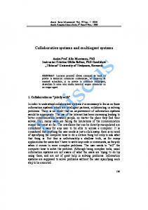
TesterAgent class. Each tester agent has a behaviour, an extension of the TestGroupExecutor class, that is in charge of getting the group of tests to be executed and for each test adds the corresponding behaviour to the tester agent scheduler. The list of all the agent-tests that can be tested and the list of task-tests to be performed for each of them are described by means of XML files. There is a single main XML file that contains the list of all the agent-tests of the application and one XML file for each agent-test that contains the list of task-tests to be executed. Developing an agent-test means therefore developing a new tester agent in charge of the group of task-tests described in the associated xml file. Finally the utility class Logger provides methods to create logs. By extending this class it is possible to create sophisticated loggers in order to provide reported information in more suitable formats. To date, reported information can be displayed in a graphical user interface (where very essential information is shown), written to a text file, printed to the standard error or organized into web pages. In the Figure 3 a class diagram of the main classes of the framework is represented.
Figure 3 - Testing framework main classes
A single test and group of tests can be executed by simply launching the corresponding tester agent. A more convenient way of performing them is by means of the TestSuiteAgent, an agent that provides a valuable graphical interface to run tests. When a test or a group of tests are launched the TestSuiteAgent creates the proper tester agent and delegates to it the execution of the tests. During the testing activity the tester agent will send FIPA ACL messages to the TestSuiteAgent, informing it about the test outcomes and giving eventually detailed information concerning the causes of failure.
4.2 TestSuiteAgent GUI The TestSuiteAgent, as stated before, provides a graphical interface to run tests, by means of which it is possible to: − View information related to the agent-tests and all the task-tests they include. − Select and load the tests to be executed. − Execute all agent-tests of the list in sequence and produce a final report indicating, for each agent-test, the number of task-tests which have passed and failed and the corresponding causes of failure. What makes this GUI particularly helpful is the binary visualisation of the results, stating whether the test has passed or failed, which cuts down considerably the time needed to analyse tests
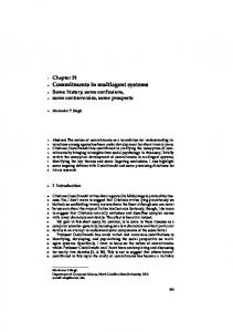
outcomes. In fact while the test is running the GUI shows its progress with a progress bar. The bar is initially green but turns into red as soon as there is an unsuccessful test. In this case, the failed tests are marked in the list and detailed information of the causes of failure are reported at the bottom. As a general rule software applications should be tested thoroughly. In particular as changes are made to the system and the added functionality is tested, previously tested functionalities have to be re-tested to assure that the modifications have not corrupted the system. In order to cut down the time of regression testing and to make the task of the developer easier, the button “RunAll” is provided in order to allow the execution of all the tests listed in the main xml file. A snapshot of the TestSuiteAgent GUI is shown in Figure 4. In this figure an example of framework use is reported that is the test of the Product agent of the application described in section 2.2. The test concerning the ProductProdtPhaseContract_init behaviour has failed. The progress bar is red (dark grey in the figure), the unsuccessful test is marked and in the lowest text area information about the causes of failure is reported (the thrown exception, in this specific case).
Figure 4 – TestSuiteAgent GUI – The Product agent is under test
5 Discussion and Conclusions The aim of the paper is to cope with important issues connected to the transition from the design phase to the implementation phase, with particular attention to testing and diagrammatic notations supporting the development process when this is very close to the actual implementation of a MAS. At first glance the work presented in this paper and the previous works, of which the present paper represents an evolution, may seem composed of loosely connected parts; in reality this is due to the nature of the problem. As a matter of fact moving inside the implementation phase means solving several issues connected with the refinement of the design models in order to facilitate code production, with the deployment of the system, with the necessity of reducing the prototype implementation time and finally with the testing activities. We think that the robust and easy-to-use test tool and the diagrammatic notations proposed, together with a CASE tool supporting them, a library of re-usable code component, and a notation supporting the representation of the deployment of MASs, are a significant step towards the widespread acceptance of the agent-oriented software paradigm. But, we are well aware that there is more. As a matter of fact more work needs to be done; other issues should be tackled. An issue, that needs to be addressed, deals with testing the MAS not at the single agent level but at the society level where a composition of different agents interact and their social behaviour should
be evaluated and compared with the expected results. Our framework can be a valid support for these kinds of test but improvements are desirable in order to give a more appropriate infrastructure. In particular we are now working in the direction of an integration of the Agent Factory1 and the testing tools in order to improve the last one (i.e. producing a repository of “mock” agents, suitable to simulate the environment around the subsystem under test). Furthermore we are considering improving the PASSI ToolKit in order to support a zooming operation of the MAZBD diagrams so that the designer could start looking at the whole system and then in order to refine his/her work he/she could exploit the representation of one agent down to the lowest level of detail. These and other further studies are left as subject for future work
References [1] Bauer B., J. P. Müller, and J. Odell. Agent UML: A Formalism for Specifying Multiagent
Interaction. Agent-Oriented Software Engineering, Paolo Ciancarini and Michael Wooldridge eds., Springer, Berlin, pp. 91-103, 2001. [2] Bellifemine, F., Poggi, A., Rimassa, G. JADE - A FIPA2000 Compliant Agent Development
Environment. In Proc. Agents Fifth International Conference on Autonomous Agents (Agents 2001), pp. 216-217, Montreal, Canada, 2001 [3] Ciancarini P., and M.J. Wooldridge. Agent-Oriented Software Engineering. Lecture Notes in
Computer Science, 1957, Springer-Verlag, 2001. [4] Cossentino M., A. Poggi, G. Rimassa, P. Turci. Implementation Level Issues in MAS Modeling.
Workshop on Object and Agents (WOA'03) Sept, 10-11, 2003. Cagliari (Italy). [5] Cossentino M., C. Potts. A CASE tool supported methodology for the design of multi-agent
systems. The 2002 International Conference on Software Engineering Research and Practice (SERP'02) - June 24 - 27, 2002 - Las Vegas (NV), USA [6] Cossentino M., L. Sabatucci, A. Chella - A Possible Approach to the Development of Robotic
Multi-Agent Systems. IEEE/WIC Conf. on Intelligent Agent Technology (IAT'03). October, 1317, 2003. Halifax (Canada) [7] Cossentino M., L. Sabatucci, S. Sorace, A. Chella. Patterns reuse in the PASSI methodology.
Engineering Societies in the Agent World 2004 (ESAW’04) workshop. London 28-31 Oct. 2003. [8] FIPA Modeling Technical Committee – Home Page – Available at
http://www.fipa.org/activities/modeling.html [9] JUnit – JUnit Home Page. Available at http://www.junit.org [10] Poggi A., G. Rimassa, P. Turci, J. Odell, H. Mouratidis, G. Manson. Modeling Deployment and
Mobility Issues in Multiagent Systems using AUML. AOSE Workshop at AAMAS 2003, Melbourne, Australia [11] Poslad S., P.Buckle, R.Hadingham. The FIPA-OS Agent Platform. Open Source for Open
Standards. Proc. of the 5th International Conference and Exhibition on the Practical Application of Intelligent Agents and Multi-Agents. Manchester, UK, April 2000, 355-368 [12] Van Leeuwen, E.H., D.H. Norrie. Intelligent manufacturing: holons and holarchies.
Manufacturing Engineer, 1997, 76(2), 86-88.
1
http://mozart.csai.unipa.it/af/