clock. It was left open whether the result could be extended to multi-clock timed networks. ... A timed process operates on a finite number of real-valued clocks.
Multi-Clock Timed Networks Parosh Aziz Abdulla, Johann Deneux, and Pritha Mahata Dept. of Information Technology Uppsala University Sweden parosh,johannd,pritha @it.uu.se �
Abstract. We consider verification of safety properties for parameterized systems of timed processes, so called timed networks. A timed network consists of a finite state process, called a controller, and an arbitrary set of identical timed processes. In a previous work, we showed that checking safety properties is decidable in the case where each timed process is equipped with a single real-valued clock. It was left open whether the result could be extended to multi-clock timed networks. We show that the problem becomes undecidable when each timed process has two clocks. On the other hand, we show that the problem is decidable when clocks range over a discrete time domain. This decidability result holds when processes have any finite number of clocks.
1 Introduction One of the main current challenges in model checking is to extend its applicability to parameterized systems. The description of such a system is parameterized by the number of components, and the challenge is to check correctness of all instances in one verification step. Most existing methods for model checking of parameterized systems consider the case where each individual component is modelled as a finite-state process. In this paper we study parameterized systems of timed processes, so called Timed Networks (TNs). A TN represents a family of systems, each consisting of a finite-state controller, together with finitely, but arbitrarily many timed processes (timed automata). A timed process operates on a finite number of real-valued clocks. This means that a TN operates on an unbounded number of clocks, and therefore its behaviour cannot be captured by that of a timed automaton [AD94]. In [AJ03], we show decidability of the controller state reachability problem for TNs: given a state of the controller, is there a computation from an initial configuration leading to that state? This problem is relevant since it can be shown, using standard techniques, that checking large classes of safety properties can be reduced to controller state reachability. The decidability result in [AJ03] is given subject to the restriction that each timed process has a single clock. As an example, this allows automatic verification of a parameterized version of Fischer’s protocol (see e.g. [KLL 97]). This protocol achieves mutual exclusion by defining timing constraints on an arbitrary set of processes each with one clock. We can show correctness of the protocol regardless of the number of participating processes. The paper [AJ03] leaves open the case of multi-clock TNs, i.e., TNs where each timed process may have several clocks. �
In the literature, there are many applications where a number of timed automata [AD94] run in parallel and where each of the timed automata has more than one clock. For instance, the Phillips audio control protocol with bus collision [BGK 96] has two clocks per sender of audio signals. Also, the system described in [MT01] consists of an arbitrary number of nodes, each of which is connected to a set of LANs. Each node maintains timers to keep track of sending and receiving of messages from other nodes connected to the same set of LANs. In a similar way to Fischer’s protocol, it is clearly relevant to ask whether we can verify correctness of the protocol in [BGK 96] regardless of the number of senders, or the protocol in [MT01] regardless of the number of nodes. The question is then whether the decidability result of [AJ03] can be extended to multi-clock systems. In this paper we answer this question negatively. In fact, we show that it is sufficient to allow two clocks per process in order to get undecidability. The undecidability result is shown through a reduction from the classical reachability problem for 2-counter machines. The main ingredient in the undecidability proof is an encoding of counters which allows testing for zero. The encoding represents each counter by a linked list of processes, where ordering on elements of the list is reflected by ordering on clock values of the relevant processes, and where the link between two elements in the list is encoded by whether two clocks belong to the same process. The value of a counter is reflected by the length of the corresponding list. We also consider Discrete Timed Networks (DTNs): a variant of timed networks where clocks are interpreted over a discrete time domain rather than a dense one. Surprisingly, it turns out that the controller state reachability problem now becomes decidable. The decidability result holds regardless of the number of clocks allowed inside ˇ each timed process. We show decidability using the theory introduced in [A CJYK00] for verification of transition systems which are monotonic with respect to a well quasiordering. More precisely, we define a counter abstraction for DTNs. This is an exact abstraction of the system where we only count the number of processes which have certain states and certain clock values. We show that such an abstraction induces a well quasi-ordering, and that the behaviour of a DTN is monotonic with respect to that ordering. �
�
Related Work Most works on verification of parameterized systems consider the case where each component is a finite-state system. Applications include cache coherence protocols [Del00,EK03], broadcast protocols [EFM99], mutual exclusion protocols with linear topologies [KMM 01], etc. In [AMC02] a method is given for translating a timed automaton with several clocks into the parallel composition of a finite number of automata each operating on a single clock. This may give the impression that reachability problems for multi-clock TNs can in a similar way be reduced to corresponding problems for single-clock TNs. However, the construction given in [AMC02] will not work in our case. The reason is that, due to the unbounded number of timed processes, it is not possible to keep track of clocks belonging to the same process. The works in [AAB00,AHV93] consider timed automata which are parameterized in the the following sense: transitions are guarded with predicates which compare clocks (and counters) with parameters possibly ranging over infinite domains. The models used �
in these papers assume a finite number of clocks and are therefore orthogonal to the models considered in this paper. A work related to our result on DTNs is [GS92] where counter abstraction is used to obtain a Petri net model for parameterized systems. However, a process in [GS92] is assumed to be finite-state. Furthermore, counter abstraction in the case of DTNs yields a model with a different behaviour than that of Petri nets. Outline: Section 2 gives the definition of timed networks. Section 3 recalls the classical model of 2-counter machines. Section 4 shows how a configuration of a 2-counter machine can be encoded by a configuration of a timed network, while Section 5 shows how the transitions of a 2-counter machine can be simulated by transitions of a timed network. We give the correctness proof for our encoding in Section 6. In Section 7 we give an algorithm for deciding the controller-state reachability problem for DTNs. Finally in Section 8, we conclude and give some directions for future work.
2 Definitions In this section, we define timed networks: families of (infinitely many) systems each consisting of a controller and an arbitrary number of identical timed processes. The controller is a finite state automaton while each process is a timed automaton [AD94], i.e., a finite-state automaton which operates on a finite number of local real-valued clocks ������������� . The values of all clocks are incremented continuously at the same rate. In addition, the network can change its configuration according to a finite number of rules. Each rule describes a set of transitions in which the controller and a fixed number of processes synchronize and simultaneously change their states. A rule may be conditioned on the local state of the controller, together with the local states and clock values of the processes. If the conditions for a rule are satisfied, then a transition may be performed where the controller and each participating process changes its state. Also, during a transition, a process may reset some of its clocks to 0. � We use and � �� for the set of natural numbers and set of non-negative real numbers respectively. Timed Networks A family of timed networks (timed network for short) � clocks is a pair ��������� , where:
with �
– � is a finite set of states. The set � is the union of two disjoint sets; the set ����� �"! of controller states, and the set �$#���%&� of process states. These sets contain two distinguished initial (idle) states, namely ')(+*-,.�0/213��� �"! and ')(+*-,�#�/415#��"%�� . – � is a finite set of rules where each rule is of the form
67 8 � = 9C> 8�: 8�: 8�B: � � 8 8�: 8�P 8�P : such that � D / E � � � F � " � ! , and for all GIH�JLP KMGIKON we have: � /4�Q#���%&� , and P= 9R> P � � is a guarded command where = is a boolean combination of predicates � ofP�the form SUTV for SW/ , TX/ZY\[]��^$��K$��_$��`5a , b/cYd � �������e�& a and > f Y� � �������e�& a .
Intuitively, the set � ���F�"! represents the states of the controller and the set �I#��"%&� represents the states of the processes. A rule of the above form describes @�@�@ 8 a set of transitions of the network. The rule is enabled if the state of the controller is 8 8B � and if there are N � @�whose processes with states ��� clock values satisfy the corresponding @�@ 8 : guards. The rule is executed by simultaneously changing the state of the controller to and the 8 : 8�B : � � � N states of the processes to , and resetting the clocks belonging to the sets � > ����������� > B . P P For a guard = we write = � � � �������e� � $� to denote the Boolean expression which reP sults from substituting the occurrences of � �������e�� in = by � � �������e� � respectively. Configurations8 A configuration � of a timed network 8 ���E����� with � clocks is a tuple 9 �Q#��"%�� , and of the form ��� � ��� ��� � , where � is a finite index set, / � ���F�"! , � H � 9 9 � H Y J ����������� a � � � . 8 Intuitively, the configuration � refers to the controller whose state is , and to ��
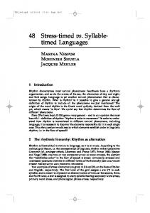
processes, whose states are defined by � . The clock values of the processes are defined by � . More precisely, for SLH J3KXS K � and G / � , � ��S �e�)G�� gives the value of clock � in the process with index G . We use �� to denote the number of processes in � , i.e., �� [� �� . Also, we shall use 9 �� such that �� +� G���[�� � S ��� G�� . �� to denote the mapping � Example 1. Figure 1 shows graphical representation of a configuration8 in a timed 8 � � Y J ��.��� a�� ���I��� � where �]��J\� [ � �����]� ��� � [ network with two clocks, given by � 8�� 8�� ���I���� � [ and � � ��Jd� [�� � J ��� ����� �Q[�� � �.��� ���!� �Q["�.� � ��� ��J\�0["�.� � ��� �� � �0[ J � # ��� ��� ��[$� � % .
Process state Controller state
q
q1
q2
q3
0.1
0.5
5.0
Value of x1
2.3
1.4
0.6
Value of x2
Fig. 1. Graphical representation of a configuration in a timed network with two clocks.
9
Transition Relation The timed network � above induces a transition relation & on 9 is the union of a discrete transition relathe set of configurations. The relation & 9(' , representing transitions induced by the rules, and a timed transition relation tion & 9& *) which represents passage of time. 9+' is the union , 9 , where & 9 represents a tran& The discrete relation & � � �-/. � sition performed according to rule 0 . Let 0 be a rule of the form described8 in the above : definition 8�: of : timed : networks. Consider : two configurations � [ �!� � ��� ��� � 9 and � . We use �2& to denote that there is an injection [ 1� � � �� � �� � � � 3 � HOY J �������e�&N a 9 � such that for each G3H J K G�KbN and SDH�J K S4Kb� we have: 1.
8
8 �8 P 3 , and P= [ � ,3 �]� � G��&��[ 3 �!� � � � G���� ���� ������� � � G��&��� holds. That is, the rule 0 is enabled.
8�:
8�:
:
8�P:
3
2. , and � � �)G�: ����[ . The states are changed according to 0 . [ 3 � > P > P then � : � 3 � G��&�Q[��� .� 3 � G���� . In 3. If � / then � � �)G��&�Q["� , while if � /
> P other words, a clock is reset to � if it occurs in the corresponding set . Otherwise its: value remains unchanged. : 3 4. � � +�$[ �]� +� and � � �Q[��� +� +� , for /+� range � � , i.e., the process states and the clock values of the non-participating processes remain unchanged.
��
��
�
��
��
8
�
��
� � � � � � �
�
For a configuration to denote the con8 : � [ ��� � : ���I��� � and Q/ �� , we use � figuration �!� � ���I��� � where � � +��[$�� .� +� : for each / � and S H�J K S KD� . : 9 ) A timed transition is of the form: �+& where � [ � : . Such a transition lets � 9() � to denote that � & 9() � time pass by . We use � & for some �/L � �� . 9 9 ' 9() and use & 9 to denote the reflexive transitive & to be & We define & 9 . Notice that if � & 9 � : then the index sets of � and � : are identical and closure of & 8 : 9 8 to therefore �� �[ � . For a configuration � and a controller state , we use � & : : 8�: : : 9 � : denote 8 : that 8 there is a configuration � of the form �!� � ��� ��� � such that � & and [ .
�
��
��
�
�
�
�
�
�
�
�
��
8
8
������
�
Reachability A configuration � � [C��� � ���I��� � is said to be initial if [ ')(+*-,+� , �I�)G�� [ ')(+*-,�# , and � .� G�� [ � for each G]/ � and S H�JLKbS2KM� . This means that an execution of a timed network starts from a configuration where the controller and all the processes are in their initial states, and the clock values are all equal to � . Notice that there is an infinite number of initial configurations, namely one for each index set � .
��
Controller State Reachability Problem (TN �)� � -Reach) 8 Instance A timed network � �E����� with � clocks and a controller state Question Is there an initial configuration �
����� �
such that �
����� � � �� &
9
8
.
?
Controller state reachability is relevant, since it can be shown, using standard techniques [VW86,GW93], that checking safety properties (expressed as regular languages) can be translated into instances of the problem. In [AJ03] we show that TN �&Jd� -Reach is decidable. In this paper we show Theorem 1. TN �1� � -Reach is undecidable.
3 2-Counter Machines In this section we recall the standard definition of counter machines.� Here, we assume that such a machine operates on two counters which we call � and . A two-counter machine is a tuple � � � where is a finite set of local states with a distinguished initial local �state � / �, and is a finite set of instructions. An � �� / instruction is a triple � � � � , where and � is either an increment (of � � the form � or ); a decrement (of the form & & or & & ); or a zero testing (of � the form � � [�� or [ � ). A configuration of a two-counter� machine is a triple � represents the local state, and � � represent the � � � � � , where / /
� $ �! �%'& '! � * � *
� ,+ � ,+ ! /. 0. ! 1�
� � �� � � ! ���"� #� � ! (! )� '% & � � . /.
�
�
�
�
values of the counters � and respectively. The counter machine induces a transition relation on the set of configurations, which is defined as usual using the standard interpretations of counter operations. We use to denote the reflexive transitive closure networks, we use of . In a similar : manner : : to timed :� : : to denote that there is a configuration [ � � � � � such that and [ . We define the initial configuration to be � � � � � � . The control state reachability problem for a 2� � check whether . The counter machines (CM-Reach) is: given local state � following result [Min61] is well-known.
�
- �! /. 0. - ����� �! ���"�
- � -
!�
- � ! ! !
- ����� � ! �
B @�@�@ B In our correctness proof : (Section 6), we use the relation , with N B `�� , on configura� tions, where iffB there is a sequence with and : B � � [ B [ . The B relation is extended to local states in a similar manner to . Notice that [ . Theorem 2. CM-Reach is undecidable.
-
� �
-
-
-
-
-
-
�
-
4 Encoding of Configurations We show undecidability of TN ��� � -Reach through a reduction from CM-Reach. Given a counter machine L[ � � � , we shall derive a timed network � �[ ��� ��� � with two clocks. In this section, we perform the first step in the reduction; namely we describe how to construct the set � . Also, we describe how configurations of are encoded as configurations of � . Finally, we introduce a special type of encodings, called proper encodings, which we use in our simulation of .
�
� ��
��
�
�
�
�� ��
�
�
States According to the model described in Section 2, the set � will consist of two disjoint sets of states: the set � ���F�"! of controller states and the set � #��"%�� of process states. The set � ��� ��! contains three types of states:
�
�
�
1. The initial controller state ')(+*-,+� . 2. Local states of : all members of have copies in � ���F�"! . 3. Temporary states: the set � ��� ��! contains a state for each increment instruction / . These states are used as intermediate states during : the simulation of increments (Section 5). The set � ���F�"! also contains the state (recall that � is the � initial local state of ). This state is used as an intermediate state in the initialization phase of the the simulation (Section 5).
$ �
�
�
�
� ��� & �
�
�
! �����
! � �"�
�
The set � #���%&� contains two types of states: 1. The initial process state ')(+*-, # . 2. Six states , ]')( , * , , 3')( , and * ters (as described below).
� �� � � ��� ��� � ���� � ��
-
�
��� ���� , used for encoding the two coun-
Encodings Each configuration of will be encoded by a set of configurations in will be encoded by the controller state. Each counter will be modelled by a counter encoding. A counter encoding arranges a set of processes as a circular list. The ordering among elements of the list is defined by the clock values.
��� . The local state of
-
The length of the list reflects to the value of the counter. To define counter encodings, we shall use the six process states � , ]')( , * (used for encoding of � ), and , (used for encoding of ). The states and * are the states of the first ]')( , * and last processes in the list encoding the value of �� . All processes in the middle of the list will be� in state ]')( . The states , ]')( 8 , and * play similar roles in the � [b�!� � ���I��� � is said to be a � -encoding encoding of . Formally, a configuration 3 J a to � such that the of value if there is an injection from the set Y�� �������e� following conditions are satisfied
� �� � � ��� ��� � � �� � � �� � � �
� �� ��� ���
.
3
– �I� ��� ��� . – �I� +3� / Y – � �� � 3 � G���� – � � � G����
.
��
�
�
[
�
��� ��� ��� �� �
�
0.
� �� , ]� � . 4Jd����[ * �� �� , and I� �)G��&� [ �]')( ')(+*-,�# �� � ��� � � �3')(�����*��� �� � a if � / � range � � . 3
�
[
�
3
3
�
.
� ���
for each G H J$K G K
3
. ^(� � � 3 � G Jd��� for each G H ��K G K � � � & � � G DJ\� ����� � +� ���&� , for each G�H � � K G�K
.
�
. DJ .
The first condition states that the processes which are part of a � -encoding are in one of the local states , 3')( , or * . The second condition states that the processes which are not part of a � -encoding are in one of the local states ')(+*-,\# � , ]')( , or . The third and the fourth conditions show how the processes which are part of * a � -encoding are ordered as a circular list. The position of each process in the list is � reflected by values of its clocks � and . More precisely, the ordering among the � � clocks reflects the positions of the processes in the list. Also, clock of each process � (except the last process) is equal to clock � of the next process. Finally, clock of the last process is equal to clock � of the first process (giving the list a “circular” form). We use �*)� � � � to denote the value of a d� -encoding � .
� �� �
�� ��
�
��� ����
�
� � �� � � ��
.
��
�
x1:
(a) fst1
mid1
mid1
x2:
last1
s
(b)
fst1
mid1
mid1
idle p
last1
idle p
0.1
0.2
0.25
4.6
0.5
6.1
0.2
0.25
0.5
0.4
0.1
5.6
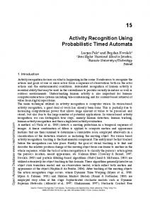
Fig. 2. (a) Graphical representation of ordering among clocks in satisfying the ordering on clocks described in (a).
�
� � -encodings. (b) a � � -encoding
Example 2. Figure 2(b) shows a � -encoding of value � . Figure 2(a) shows a graphical representation of the ordering among clock values. In Section 5 we shall use such a graphical representation to explain the different steps in the simulation of . Each ellipse
�
contains clocks of equal values. Clocks in successive ellipses have increasing values, i.e., they are ordered from left (lower clock values) to right (higher clock values). The upper� halves of the ellipses represent the � -clocks, while the lower halves represent the -clocks. Each process is denoted by an edge whose end points are its two clocks. Such an edge is labelled by the current state of the process.
�
��
�
�
A -encoding and its value �* � � � are defined in a similar manner (replacing the states , ]')( , and * by8 , 3)' ( , and * in the encoding). A configuration � [ �!� � ���I��� � is said to be an encoding if the following two conditions are satisfied:
� �� � �
– – If
'
�
8
[
!
��� ��
! �
� �� � � ��
��� ����
8
�
for some $/ ,� i.e., is the copy of a local state of . is both a � - and a -encoding.
�
�
satisfies the above conditions (i.e. if �
�
is an encoding), we define� the signature �
�
�! /. /. �! /. 0.
.
.
� � � of � to be the triple � � � �� � � , where �L[ � ��*)� � � � and [ � ��* � � � . � will correspond to a configuration of . Notice that Intuitively, the triple � � �\� �
�
several (in fact infinitely many) configurations may have the same signature. However, all such configurations will have the same local states and the same orderings on clock values, and therefore will correspond to the same configuration in .
�
�
Proper Encodings In our simulation of we shall rely on a particular kind of encod8 ings, called proper encodings. An encoding � of the form �!� � ��� ��� � is said to be proper if it satisfies the following condition: – For each G /
with ] � � G�� [ �
')(+*-,�# , �]^
�
� �)G��e��� �
�)G�� ^ J .
In other words, all clocks participating in the encoding have values between (not including) zero and one. Certain steps of the simulation (see the decrementing operation in Section 5) are not possible to carry out without an upper bound on clock values of the processes. Working with proper encodings guarantees such an upper bound (namely an upper bound of one).
5 Encoding of Transitions
�
[ In this section, we perform the second step in deriving the timed network � � � ��� � from the counter machine L[ � � � . More precisely, we describe the set of contains the following rules: rules � . The set �
�
� ��
�
��
$
� ��
�! (� � ]�(!
Incrementing For each instruction 3[M� �\� �� namely 67 ;< 67
�
'����
�
H
67
��� 9 & �
!
�
� ��
3^2�� 9 �3')(
��� & �
and the rule
�
!��
9
'���� � H
�
; B 8 B:
:
� & �
.
we compute a finite set of configurations � such that ] G"N�� �Q� . We '�� 8 �0�, � � � � [ define � to be the set of all configurations of the form � � ���I��� such that there � are three pairwise disjoint sets � � '�� �� � � � � , ( and � /0�(�'�� of indices and the following holds.
�
:
�
�
�
�
– � [ �� � '�� � ���� � ,( , � � � � , ( � 0 � ( '�� , and – �][ � � '�� 3 9 Y J �������e�&N a , which satisfies the – there is a bijection H � � '�� � /0�(�'�� following conditions. 8���� � � � 1. �I� +� [
�� , and the guard = �� �!� � � +� �����������E �� +��� holds. Furthermore, � ��S �e� �3/XY�� �������e�
DJ a , for each / � �� � '�� � 0�( '�� � and for each � S H $ J 4 K � S 2 K � . : 8 ��: � 2. � � ��[
�� for / �� � '�� . : 3. � � ��[ �]� +� for E/ � ���� : � , ( . > ��� �� . 4. For each S�H J$K2S�K4� , � � +� [$� if / � � '�� and � ]/ 5. For each��� S2H�JLKbS2K � and for each such that either : / � � '�� and > �� , or E/ � ���� � , ( , � � ��[ G�N�� �� J ��� � +�&� .
/
�
��
�� ��
�
�
��
�
�
��
� �
� �
�
�
��
�
�
�� �
��
��
�
�
�
�� �
.
�
�
.
�
�
��
�
Observe that
.
�
– The set � /0�(�'�� of indices with size can correspond to infinitely many sets of the same size. We equate all of them modulo renaming. Therefore, the sets � � '�� � � � � � , (�� � /0�(�'�� are finite and effectively constructible. – The conditions on the controller states are implicitly included by our notation, : which requires the controller states of � and � to be the controller states of 0 . – The correctness of the above algorithm can be shown in a similar manner to the proofs in [AJ03].
�
�
�
This, together with Theorem 5, proves Theorem 4.
8 Conclusions, Discussion, and Future Work We have shown undecidability of controller state reachability for multi-clock timed networks. We have also shown decidability of the problem when clocks are interpreted over a discrete time domain. In this paper, we assume a lazy behaviour for TNs. This means that we may choose to let time pass instead of performing discrete transitions, even if that makes these transitions disabled, due to some of the clocks becoming “too old”. In fact, we can use the techniques in [JLL77] to show that, in the case of urgent behaviour, the controller state reachability is undecidable even for single-clock TNs. Also, in this paper we only consider safety properties. Liveness properties have been shown to be undecidable for single-clock TNs in [AJ03]. The ordering we provide for proving decidability of DTN corresponds to an abstraction of configurations where we count the number of processes which are in a certain state and which have certain clock values. In a similar manner to [GS92] we can view this abstraction as a “Petri net”-like model where each place corresponds to one combination of process states and clock values. In contrast to [GS92], the transitions in the abstract model do not correspond to those of a Petri net. The main difference is that a timed transition simultaneously moves all tokens from each place, corresponding to a certain clock value, to the place corresponding to the next clock value. Comparing to the model of Transfer Nets [FRSB02], a timed transition here corresponds to “parallel transfers”, i.e. a set of transfers which are performed simultaneously. An alternative way to prove our decidability result would be to simulate a DTN by a transfer net. One ingredient in such a simulation is to simulate parallel transfers by sequences of transfer operations. There are several classes of protocols which can be modelled as multi-clock TNs, such as the parameterized versions of the protocols in [BGK 96] and [MT01]. This means that, despite our undecidability result, it is interesting to design semi-algorithms for multi-clock TNs. One direction for future work is to design acceleration techniques which are sufficiently powerful to handle such classes of protocols. �
References [AAB00]
A. Annichini, E. Asarin, and A. Bouajjani. Symbolic techniques for parametric reasoning about counter and clock systems. In Proc. CAV’00, volume 1855 of LNCS, 2000. ˇ ˇ ans, Bengt Jonsson, and Tsay Yih-Kuen. Algo[ACJYK00] Parosh Aziz Abdulla, Karlis Cer¯ rithmic analysis of programs with well quasi-ordered domains. Information and Computation, 160:109–127, 2000. [AD94] R. Alur and D. Dill. A theory of timed automata. Theoretical Computer Science, 126:183–235, 1994. � [AHV93] R. Alur, T. Henzinger, and M. Vardi. Parametric real-time reasoning. In Proc. ���� ACM Symp. on Theory of Computing, LNCS, pages 592–601, 1993. [AJ03] Parosh Aziz Abdulla and Bengt Jonsson. Model checking of systems with many identical timed processes. TCS, 290(1):241–264, 2003. [AMC02] E. Asarin, O. Maler, and P. Caspi. Timed regular expressions. The Journal of ACM, 49(2):172–206, 2002.
[BGK 96] J. Bengtsson, W. O. D. Griffioen, K.J. Kristoffersen, K.G. Larsen, F. Larsson, P. Pettersson, and W. Yi. Verification of an audio protocol with bus collision using UPPAAL. In Proc. CAV’96, volume 1102 of LNCS, pages 244–256, 1996. [Del00] G. Delzanno. Automatic verification of cache coherence protocols. In Proc. CAV’00, volume 1855 of LNCS, pages 53–68, 2000. [Dic13] L. E. Dickson. Finiteness of the odd perfect and primitive abundant numbers with distinct prime factors. Amer. J. Math., 35:413–422, 1913. [EFM99] J. Esparza, A. Finkel, and R. Mayr. On the verification of broadcast protocols. In Proc. LICS’99, 1999. [EK03] E.A. Emerson and V. Kahlon. Model checking guarded protocols. In Proc. LICS’03, 2003. [FRSB02] A. Finkel, J.-F. Raskin, M. Samuelides, and L. Van Begin. Monotonic extensions of petri nets: Forward and backward search revisited. In Proc. Infinity’02, 2002. [GS92] S. M. German and A. P. Sistla. Reasoning about systems with many processes. Journal of the ACM, 39(3):675–735, 1992. [GW93] P. Godefroid and P. Wolper. Using partial orders for the efficient verification of deadlock freedom and safety properties. Formal Methods in System Design, 2(2):149– 164, 1993. [JLL77] N. D. Jones, L. H. Landweber, and Y. E. Lyen. Complexity of some problems in Petri nets. Theoretical Computer Science, (4):277–299, 1977. [KLL 97] K.J. Kristoffersen, F. Larroussinie, K. G. Larsen, P. Pettersson, and W. Yi. A compositional proof of a real-time mutual exclusion protocol. In Proc. TAPSOFT ’97, LNCS, 1997. [KMM 01] Y. Kesten, O. Maler, M. Marcus, A. Pnueli, and E. Shahar. Symbolic model checking with rich assertional languages. Theoretical Computer Science, 256:93–112, 2001. [Min61] M. Minsky. Recursive unsolvabitity of post’s problem of tag and other topics in the theory of turing machines. Ann. of Math., 74:437–455, 1961. [MT01] I. A. Mason and C. L. Talcott. Simple network protocol simulation within maude. In ENTCS, volume 36. Elsevier, 2001. [VW86] M. Y. Vardi and P. Wolper. An automata-theoretic approach to automatic program verification. In Proc. LICS’86, pages 332–344, 1986. �