Multi-Model and Multi-Level Development of User Interfaces Jean Vanderdonckt*, Elizabeth Furtado, João José Vasco Furtado, Quentin Limbourg*, Wilker Bezerra Silva, Daniel William Tavares Rodrigues, and Leandro da Silva Taddeo *Université catholique de Louvain ISYS/BCHI Institut d’Administration et de Gestion Place des Doyens, 1 Louvain-la-Neuve, B-1348 Belgium
[email protected] [email protected]
Universidade de Fortaleza NATI - Célula EAD Washington Soares, 1321 – Bairo Edson Queiroz Fortaleza (Ceará), BR-60455770 Brazil
[email protected],
[email protected],
[email protected],
[email protected],
[email protected]
Abstract Universal design of user interfaces addresses design issues in multiple contexts of use where multiple types of users carry out multiple tasks, possibly in multiple domains of interest. Existing development methods do not necessarily support the development of such user interfaces, as they do not establish commonalities and differences between these multiple interfaces in different contexts of use. To address this need, a new development method is presented based on three levels of abstraction: (i) a conceptual level where a domain expert defines an ontology of concepts, relationships, and attributes of the domain of discourse, including user modelling; (ii) a logical level where a designer specifies multiple models based on the previously defined ontology and its rules; and (iii) a physical level where a developer develops multiple user interfaces from the previously specified models based on characteristics in the user models.
Keywords Automated generation of user interfaces, computer-aided design of user interfaces, conceptual level, context of use, instantiation, logical level, model-based approach, modelling, multi-level, multi-model, ontology, physical level, universal design.
Introduction In universal design [18], user interfaces (UIs) of interactive applications are developed for a wide population of users in different contexts of use by taking into account factors such as preferences, cognitive style, language, culture, habits and system experience. Universal design of single or multiple UIs (MUIs) poses some difficulties due to the consideration of these multiple parameters. In particular, the multiplicity of parameters dramatically increases the complexity of the design phase by adding a large number of design options. The number and scope of these design options increase the variety and complexity of the design. In addition, methods for developing UIs have difficulties with this variety of parameters because the factors are not necessarily identified and manipulated in a structured way nor truly considered in the standard design process. The goal of this chapter is to present a structured method addressing certain parameters required for universal design. The method is supported by a suite of tools based on two components: (i) an ontology of the domain of discourse and (ii) models that capture instantiations of concepts identified in this ontology in order to produce multiple UIs for multiple contexts of use. These different UIs exhibit different presentation styles, dialogue genres and UI structures. The remainder of this chapter is structured as follows: • The first section provides a state of the art of methods for developing UIs with a focus on universal design. • The next section defines a model in this development method, along with desirable properties. As this chapter adopts a conceptual view of the problem, the modelling activity will be organized into a layered architecture manipulating several models. • The three levels are then described respectively in the three next sections: conceptual in the third section, logical in the fourth section, and physical in the fifth section.
1
• •
The application of this method is demonstrated through the example of a UI for patient admission at a hospital. The last section summarizes the main points of the paper.
Related Work The authors’ Interactive Dialogue Environment (AIDE) [7] is an integrated set of interactive tools enabling developers to implement UIs by directly manipulating and defining UI objects, rather than by the traditional method of writing source code. AIDE provides developers with a more structured way of developing UIs as compared to traditional “rush-to-code” approaches where unclear steps can result in a UI with low usability. The User-Centered Development Environment (UCDE) [2] is an object-oriented UI development method for integrating business process improvements into software development. Business-oriented components are software objects that model business rules, processes and data from the end-user’s perspective. The method maps data items onto UI objects that are compatible with the parameters of the data item (e.g., data type, cardinality). The advantage of UCDE is that it provides a well-integrated process from high-level abstraction to final UI. Another methodological framework for UI development described by Hartson and Hix [9,10] integrates usability issues into the software development process from the beginning. The focal point of this approach is a psychologically based formal task description, which serves as the central reference for evaluating the usability of the user interface under development. This framework emphasizes the need for a task model as a starting point for ensuring UI usability, whereas UCDE emphasizes the need for a domain model. The MUSE method [11] uses structured notations to specify other elements of the context of use, such as organizational hierarchies, conceptual tasks and domain semantics. In addition, structured graphical notations are provided to better communicate the UI design to users. The above approaches illustrate the importance of using a structured method to capture, store, and manipulate multiple elements of the context of use, such as task, domain and user. Although the above methods partially consider this information, they do not consider designing multiple UIs where task [5,6], domain and user parameters vary, sometimes simultaneously. The Unified User Interface design method [18] was the first method to suggest deriving multiple variations of a task model so as to take into account individual differences between users. The different variations of a task model are expressed by alternative branches showing what action to perform depending on particular interaction styles. Thevenin and Coutaz [19,20] go one step further by introducing the concept of decorating a task, which is a process that introduces graphical refinements in order to express context ualisation. The task is first modelled independently of any context of use, and thus independently of any type of user. Depending on the variations of the context of use to be supported, including variations of users, the initial task model is refined into several decorated task models that are specific to those contexts of use. Paternò and Santoro [14] show the feasibility of deriving multiple UIs from a single model by decomposing the task differently based on different contexts of use. For each context of use, different organizations of presentation elements are selected for each task . In this paper, we consider how a single task model can represent the same task across different user profiles. In the following sections we address the following questions: Do we need to create a single task model where all differences between users are factored out? In this case, do we start by creating a different task model for each user stereotype and then create a unified model that describes only the commonalities? Or do we start with a single task model that includes both commonalities and differences between users? And if so, how do we isolate commonalities from differences? To address these questions, we first set up the foundations for our modelling approach.
Definition of Model Several computer science methodologies decompose a modelling activity into a multi-leveled architecture where models are manipulated explicitly or implicitly: model engineering (e.g., Object-Modelling Technique [17], UML [1]), database engineering and certain information system development methodologies (e.g., SADT [12]). Similarly, the method proposed here structures the UI development process into three levels of abstraction (Figure 1): 2
1. 2.
3.
The conceptual level allows a domain expert to define the ontology of concepts, relationships, and attributes involved in the production of multiple UIs. The logical level allows designers to capture requirements for a specific UI design case by instantiating concepts, relationships, and attributes with a graphical editor. Each set of instantiations results in a set of models for each design case (n designs in Figure 1). The physical level helps developers derive multiple UIs from each set of models with a model-based UI generator: in Figure 1, m possible UIs are obtained for UI design #1, p for UI design #2,…, r for UI design #n. The generated UI is then exported to a traditional development environment for manual editing. Although the editing can be performed in any development environment, the tools dis cussed here support code generation for Microsoft Visual Basic V6.0.
Conceptual level
Ontology editor
Ontology for UI design
Logical level Concept editor (graphical)
Models for UI design #1
Models for UI design #2
...
Models for UI design #n
Physical level Model-based UI generator
UI 1.m for UI design #1 1.2 for . . UIUIdesign #1 . UI 1.1 for UI design #1
UI 2.p for UI design #2 2.2 for . . UIUIdesign #2 . UI 2.1 for UI design #2
...
UI n.r for UI design #n . . UI n.2 for . UI design #n UI n.1 for UI design #n
Microsoft Visual Basic
Final UI 1.m Final UI 2.p for design #1 for design #1 . . Final UI 1.2 . . Final UI 2.2 for design #1 . . for design #1 Final UI 1.1 Final UI 2.1 for design #1 for design #2
...
Final UI n.r for design #n . . Final UI n.2 . for design #n Final UI n.1 for design #n
Universal design Figure 1. Levels of the proposed method for universal design of user interfaces A UI model is a set of concepts, a representation structure and a series of primitives and terms that can be used to explicitly capture knowledge about the UI and its related interactive application using appropriate abstractions. A model is assumed to abstract aspects of the real world. Any concept of the real world can therefore lead to multiple possibilities of abstraction depending on how we want to develop UIs. Ideally, a model should be 3
declarative rather than imperative or procedural. It should also be editable, preferably through tools, and finally it should be analysable, so as to allow some degree of automation. A model consists of a number of features (Figure 2). It is typically built as a hierarchical decomposition of abstract concepts into more refined sub-concepts. Any concept can then be characterized by a name, a description and properties of interest. A model should also encompass relationships between these concepts with roles. These relationships apply both within models (called intra-model relationships) and between models (called inter-model relationships). Any of these relationships (i.e., the definition, the decomposition, the intra- or inter-model relationships) can possess a number of attributes. DECOMPOSITION Is decomposed into
Decomp. attributes 0-n
MODEL
DEFINITION
Features
Definition attributes
CONCEPT
Is composed of
0-n
Name Description Properties
MODEL RELATION CONCEPT RELATION Relation features Concept rel. attributes
Figure 2. Definition of the user interface model How many models do we need? A single UI model is probably too complex to handle because it combines all static and dynamic relationships in the same model. It is also preferable to avoid using a large number of models, because this requires establishing and maintaining a large number of relationships between the models. Model separability is desirable in this case. Model separability adheres to the Principle of Separation of Concerns, which states that each concept should be clearly separated from the others and classified in only one category. Therefore, the quality of separability depends on the desired results and the human capacity to properly identify and classify concepts. Table 1 summarizes a list of desirable model properties. Property Completeness Graphical completeness Consistency
Correctness Expressiveness Conciseness Separability Correlability Integrability
Definition Ability of a model to abstract all real world aspects of interest via appropriate concepts and relationships Ability of a model to represent all real world aspects of interest via appropriate graphical representations of the concepts and relationships Ability of a model to produce an abstraction in a way that reproduces the behaviour of the real world aspect of interest in the same way throughout the model and that preserves this behaviour throughout any manipulation of the model Ability of a model to produce an abstraction in a way that correctly reproduces the behaviour of the real world aspect of interest Ability of a model to express any real world aspect of interest via an abstraction Ability of a model to produce compact abstractions of real world aspects of interest Ability of a model to classify any abstraction of a real world aspect of interest into one single model (based on the Principle of Separation of Concerns) Ability of two or more models to establish relationships between themselves so as to represent a real world aspect of interest Ability of a model to bring together abstractions of real world aspects of interest into a single model or a small number of models Table 1. Desirable properties of a model
With respect to these properties, some research proposes that model integrability (where all abstractions are concentrated into one single model or, perhaps, a few of them) can avoid model proliferation and can better achieve modelling goals than model separability (where the focus is only on one particular aspect of the real world at a time to be represented and emphasized). On one hand, integrability promotes integration of concepts and relationships, thus reducing the need to introduce artificial relationships to maintain consistency. Integrability also improves access to the concepts. On the other hand, integrability demands a careful consideration of the concepts to be integrated and may become complex to manipulate. In contrast, with 4
separability, each concept is unequivocally classified into one and only one model. However, this may increase the number of models and relationships needed to express all dependencies between the models. In the following sections, different types of models will be defined for different levels of abstraction. We begin with the top level and continue with the subsequent levels.
Conceptual Level Definition Each method for developing UIs possesses its own set of concepts, relationships and attributes, along with possible values and ways to incorporate them into the method. However, this set is often hidden or made implicit in the method and its supporting tool, thus making the method insufficiently flexible to consider multiple parameters for universal design. When the set of concepts, relationships and attributes is hidden, we risk manipulating fuzzy and unstructured pieces of information. The conceptual level is therefore intended to enable domain experts to identify common concepts, relationships and attributes of the models involved in universal design. The identification of these concepts, relationships and attributes will govern how they will be used in future models when manipulated by the method. An ontology explicitly defines any set of concepts, relationships, and attributes that need to be manipulated in a particular situation, including universal design [6,18]. The concept of ontology [8] comes from Artificial Intelligence where it is identified as the set of formal terms with which one represents knowledge, since the representation completely determines what “exists” for the system. We hereby define a context of use as the global environment in which a user population, perhaps with different profiles, skills and preferences, carries out a series of interactive tasks on one or multiple semantic domains [15]. In universal design, it is useful to consider many types of information (e.g., different user profiles, different skills, different user preferences) in varying contexts of use. This information can be captured in different models [13,16]. A model is a set of postulates, data and inferences presented as a declarative description of a UI facet. Many facets exist that are classified into one of the following models: task, domain, user, interaction device, computing platform, application, presentation, dialogue, help, guidance, tutorial, organizational environment. A model is typically built as a hierarchical decomposition of abstract concepts into several refined sub-levels. Relationships between these concepts should be defined with roles, both within and between models. To avoid incompatible models, a meta-model defines the language with which any model can be specified. One of the most frequently used meta-models, but not the only one, is the UML meta-model. The concepts and relationships of interest at this level are meta-concepts and meta-relationships belonging to the meta-modelling level. Figure 3 exemplifies how these fundamental concepts can be defined in an ontology editor. In Figure 3, the core entity is the concept, characterized by one or many attributes, each having here a data type (e.g., string, real, integer, Boolean, or symbol). Concepts can be related to each other. Relationships include inheritance (i.e., “is”), aggregation (i.e., “composed of”) and characterization (i.e., “has”). At the meta-modelling stage, we do not yet know what type of concepts, relationships, and attributes will be manipulated. Therefore, any definition of a UI model, as represented in Figure 2, can be expressed in terms of the basic entities as specified in Figure 3.
5
Figure 3. The ontology editor at the meta-modelling level
Case study The context of use can theoretically incorporate any real world aspect of interest, such as the user, the software/hardware environment, the physical and ambient environment, the socio-organizational environment, etc. For the simplicity of this paper, the context of use focuses on three models: 1.
2.
3.
A domain model defines the data objects that a user can view, access, and manipulate through a UI [16]. These data objects belong to the domain of discourse. A domain model can be represented as a decomposition of information items, and any item may be iteratively refined into sub-items. Each such item can be described by one or many parameters such as data type and length. Each parameter possesses its own domain of possible values. A task model is a hierarchical decomposition of a task into sub-tasks and then into actions, which are not decomposed [14,15,21]. The model can then be augmented with temporal relationships stating when, how and why these sub-tasks and actions are carried out. Similarly to the domain model, a task model may have a series of parameters with domains of possible values -- for instance, task importance (low/medium/high), task structure (low/medium/high decomposition), task critical aspects (little/some/many), and required experience (low/moderate, high). A user model consists of a hierarchical decomposition of the user population into stereotypes [16,22]. Each stereotype brings together people sharing the same value for a given set of parameters. Each stereotype can be further decomposed into sub-stereotypes. For instance, population diversity can be reflected by many user parameters such as language, culture, preference (e.g. manual input vs. selection), level of task experience (elementary, medium, or complex), level of system experience (elementary, medium, or complex), level of motivation (low, medium, high), and level of experience of a complex interaction medium (elementary/medium/complex).
Other characterization of these models in terms of their parameters, or even other model definitions, can be incorporated depending on the modelling activity and the desired level of granularity.
6
Figure 4. The ontology editor at the modelling level Figure 4 graphically depicts how the ontology editor can be used at the modelling stage to input, define and structure concepts, relationships and attributes of models with respect to a context of use. Here, the three models are represented and they all share a description through parameters. Each parameter has a domain; each domain has a set of values, possibly enumerated. The “composed-of” relationship denotes aggregation, while “has” denotes properties. The definition of an ontology encourages structured UI design based on explicit concepts, relationships, and attributes. This structured approach contrasts with eclectic or extreme programming where the code is produced directly; it also contrasts with design methods that are not open to incorporating new or custom information as required by universal design. A UI ontology facilitates multi-disciplinary work where people from different backgrounds need to gather for collaborative or participatory design. The advantage of this level is that the ontology can be defined once and used as many times as desired. When universal design requires the consideration of more information within models or more models, the ontology can be updated accordingly, thereby updating the method for universal design of UIs. This does not mean that the subsequent levels will change automatically, but their definition will be subsequently constrained and governed so as to preserve consistency with the ontology. Once an ontology has been defined, it is possible to define the types of models that can be manipulated in the method, which is the goal of the logical level.
Logical Level Definition Each model defined at the conceptual level is now represented with its own information parameters. For example, in the context of universal UI, a user model is created because different users might require different UIs. Multiple user stereotypes, stored as user models, allow designs for different user types in the same case study. Any type of user modelling can be performed since there is no predefined or fixed set of parameters. This illustrates the generality of the method proposed here to support universal design. The set of concepts and attributes defined in the ontology are instantiated for each context of use of a domain. This means each model, which composes a context of use, is instantiated by defining its parameters with domains of possible values .
7
Case study In this example we use the ontology editor to instantiate the context of use, the relationships and attributes of models for the Medical Attendance domain involved in patient admission. Figure 3 graphically depicts the Emergency Admission context of use and the attributes of models of task, user and domain. Two tasks are instantiated: Admit patient and Show patient data. The first one is activated by a Secretary and uses Patient information during its execution. For the user model of the secretary, the following parameters are considered: the user’s experience level, input preference and information density with the values low or high. The data elements describing a patient are the following: date, first name, last name, birth date, address, phone number, gender and civil status. Variables for insurance affiliation and medical regime can be described similarly. The variable parameters of a domain model depend on the UI design process. For instance, parameters and values of an information item used to generate UIs in [22,23] are: data type (date, Boolean, graphic, integer, real, or alphanumeric), length (n>1), domain definition (know, unknown, or mixed), interaction direction (input, output, or input/output), orientation (horizontal, vertical, circular, or undefined), number of possible values (n>1), number of values to choose (n>1), and preciseness (low or high).
Figure 5.The ontology editor at the instance level Figure 6 shows parameters of the model that has been previously introduced. At this stage the parameters are listed but not instantiated. The parameters will be instantiated at the instance level. All of this information can then stored in a model definition file that can be exported for future use.
8
Figure 6. Some definitions at the modelling level Models defined and inputted at the logical level are all consistently based on the same ontology. The advantage is that when the ontology changes, all associated models change accordingly since the ontology is used as the input to the graphical editor. The graphical nature of the editor improves the legibility and the communicability of information, while information that cannot be represented graphically is maintained in text properties. The models are used for both requirements documentation and UI production in the next level. As we have mentioned, it is possible to use any method for modelling tasks and users since there is no predefined or fixed set of parameters. Since there are many publications describing the rules for combining these parameters in order to deduce UI characteristics, we developed a rule module linked to the ontology editor. The rules can manipulate only entities in the logical level. The meta-definition at the conceptual level can be changed by domain experts (e.g., adding/deleting/modifying any attribute, model or relationship, but not by designers. Once the meta-definition is provided to designers, they can only build models that are compatible with the metadefinition.
Figure 7. The editing of a rule using model parameters Figure 7 shows the editing of a rule for optimising user interaction style based on several parameters [24]. The rule depicted in Figure 7 suggests natural language as the interaction style when the following conditions are met: the task experience level (attribute coming from the user model) is rich, the system experience of the user is 9
moderate, task motivation is low, and the user is experienced with modern interactive devices (e.g. touch screen, track point, trackball). When natural language is selected, appropriate design choices can be inferred. The advantage of this approach is that it is possible to easily define new rules when a new parameter is added to the models. Any rule can be produced to derive new design elements from user, task and system characteristics in a systematic way.
Physical Level Definition The main goal of the physical level lies in its ability to exploit instantiations captured in individual models to produce multiple UIs for different computing platforms, development environments and programming languages. This level is the only one that is dependent on the target hardware/software configuration intended to support the UI. Instantiations of the previously defined models, along with the values of their parameters, are stored in the logical level in specification files. Each specification file consists of a hierarchical decomposition of the UI models into models, parameters, values, etc. maintained in an ASCII file. Each instance of each concept is identified by an ID. All relationships and attributes are written in plain text in this file in a declarative way (e.g., Define Presentation Model Main;…; EndDef;). This file can in turn be imported into various UI editors as needed. Here, the SEGUIA [23] tool is used (Figure 8): it consists of a model-based interface development tool that is capable of automatically generating code for an executable UI from a file containing the specifications defined in the previous step. Of course, any other tool that is compliant with the model format, or that can import the specification file, can be used to produce an executable UI for other design situations, contexts of use, user models, or computing platforms. SEGUIA is able to automatically generate several UI presentations to obtain multiple UIs. These different presentations are obtained either: a)
In an automated manner, where the developer launches the UI generation process by selecting which layout algorithm to use (e.g. two -column format or right/bottom strategy) b) In a computer-aided manner, where the developer can see the results at each step, can work in collaboration with the system, and can control the process.
Import list box
Current item definition
Figure 8. SEGUIA environment displaying the case study specifications before UI generation
10
In Figure 8, the left-hand column contains the information hierarchy that will be used to generate multiple presentation styles for MUIs. The right-hand column displays individual parameters for each highlighted data item in the hierarchy.
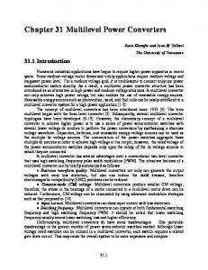
Case study In our case study, information items and their values introduced at the modelling stage (Figure 5 and 6) are imported into an Import list box of data items (left-hand side of Figure 8). Each of these items is specified separately in the Current item definition for viewing or editing (right-hand side of Figure 8). By selecting Generation in the menu bar, the developer launches the UI generation process and produces different user interfaces depending on the rules used for this purpose. Selection rules automatically select concrete interaction objects (or widgets) by exploiting the values of parameters for each data item. For instance, the PatientFirstName information item is mapped onto a single line edit box (as Abstract Interaction Object) that can be further transformed into a Single-line entry field (as Concrete Interaction Object belonging to the MS Windows computing platform). Selection rules are gathered in different selection strategies. Once concrete widgets are defined, they can be automatically laid out. Figure 9 shows the results of the code generation for the Patient Admission as defined in this case study. This layout strategy places widgets in two balanced columns by placing widgets one after another. This procedure can result in unused screen space, thus leading to a sub-optimal layout (Figure 9)
Unused screen spaces Figure 9. Patient admission window statically generated by the two-columns strategy (with unused screen spaces).
11
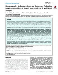
Figure 10. Patient admission window interactively generated by the right/bottom strategy To avoid unused screen space and to improve aesthetics, a right/bottom layout strategy has been developed and implemented [22,23]. Figure 10 shows how this strategy can significantly improve the layout. Note the optimisation of the upper-right space to insert push buttons, the right alignment of labels (e.g. between the date and the “Patient” group box) and the left alignment of edit fields. The method is very flexible at this stage, allowing the designer to experiment with different design options such as selection of widgets and layout strategies. For instance, some strategies apply rules for selecting purely textual input/output widgets (e.g. an edit box), while others prefer widgets displaying graphical representations (e.g. a drawn button or an icon). The layout can also change according to the native language of the end-user. Figure 11 shows the Patient Admission window re-generated after switching the Gender group box from a textual modality to a graphical modality (here, a radio icon) and switching the end user native language from English to French. The previous generation process can be reused for the logical positions of widgets. Thus by changing the value of just one parameter in the existing design options, it is possible to create a new UI in another language with an alternative design. Note in Figure 11 that some alignments changed with respect to Figure 10 due to the length of labels and new widgets introduced in the layout. The layout itself can be governed by different strategies ranging from the simplest (e.g., a vertical arrangement of widgets without alignment as in Figure 12 but for the Apple Macintosh computing platform) to a more elaborate one (e.g., layout with spatial optimisation as in Figure 11).
Figure 11. Patient admission window re-generated for a graphical icon and a different user language
12
Figure 12. Patient admission re-generated for a different computing platform At this stage it is possible to share or reuse previously defined models for several UI designs, which is particularly useful when working in the same domain as another UI. The approach also encourages users to work at a higher level of abstraction than merely the code and to explore multiple UI alternatives for the same UI design case. This flexibility can produce UIs with unforeseen, unexpected or under-explored features. The advantage of this method is that when the set of models change, all UIs that were created from this set can change accordingly on demand. The design space is often referred to as the set of all possible UIs that can be created from an initial set of models for one UI design. When a UI is generated for a target context of use, for example a target computing platform, it can be edited not only in SEGUIA, but also in the supported development environment for this computing platform. For example, Figure 13 represents the dialogue box of widget parameters generated in SEGUIA for a particular UI. The developer can of course edit these parameters, but should be aware that any change at this step can reduce the quality of what was previously generated. Changing the values of parameters in an inappropriate way should be avoided. Once imported in MS Visual Basic, for instance, these parameters can be edited by changing any value.
Figure 13. Parameters of a concrete interaction object (widget)
13
Summary of Development Process The three levels of the development method are represented in Figure 14. This figure shows that each level, except the ultimate one, is governed by concepts defined at the next higher level. The meta-model level is assumed to remain stable over time, unless new high-level objects need to be introduced. Only the main objects of the model definition in Figure 2 are incorporated. Possible models and their constituents are then defined at the model level as concepts, relationships, and attributes of the meta-model level. Again, the model level should remain stable over time, unless new models need to be introduced (e.g., a platform model, an organization model) or existing models need to be modified (e.g., the user model needs to include a psychological and cognitive profile).
Figure 14. The different levels of the proposed method For each case study, a new instance level will be produced for each model level. For instance, figures 15 and 16 exemplify UIs generated by the method with the SEGUIA tool for another context of use. The task consists of regis tering a child for leisure activities in a children’s club. In the domain model, each child has specific information (such as first name, birth date), is related to one or many parents (described by their first name, last name, address, phone number, phone number in case of need) and at most two recreation activities (described by a name, a monitor, beginning and ending dates and times). The user model is restricted to only one profile: a secretary working in a traditional office environment. The upper left part of the window reproduced in Figure 15 illustrates the task status based on another rule defined at the model level: for the task to be completed, all information related to the child, at least one corresponding parent or relative, and two recreation activities are required. Therefore, a green or red flag is highlighted according to the current status of the task: here, the parent has been completely and properly input, but not yet the child and the activities. The second activity is still greyed out as nothing has been entered yet. The presentation is governed by the following rule: each object should be presented in the same window (to avoid confusing users), but in different tabs of the window (here, “Parent”, “Enfant”, “Activité 1”, and “Activité 2”).
14
Figure 15. Case study: registering a child for recreational activities (first part) Figure 16 presents another rule working this time on the presentation model. Each group of information items related to the same entity (i.e., a child, a parent, an activity) is assembled in a group box; this box is laid out using the optimised algorithm presented above and emphasized in a distinctive colour scheme. The group boxes are therefore presented in blue (parent), yellow (child), red (first activity), and green (second activity). The colours are chosen from the standard palette of colours. Such rules cannot be defined in a logical way in traditional development environments. But they can of course be defined manually, which becomes particularly tedious for producing MUIs.
15
Figure 16. Case study: registering a child for recreational activities (second part) For the same case study, Figure 17 presents an alternative UI for a slightly different profile requiring more guidance to achieve the task step by step. Rather than using a graphical overview in the upper part of the window (as in Figure 15) and multiple tabs, the UI progressively proceeds from one task to the next by adding tabs each time a sub-task is finished. Therefore, the rule coded here is: present each object in a separate tab; once a subtask is carried out, add a new tab with the next object for the next sub-task to be carried out and add buttons to move forward and backward as in a set-up wizard.
Figure 17. Alternate layout for the task: registering a child to leisure activities.
16
Conclusion The UI design method can be explicitly structured into three separate levels (i.e., conceptual, logical, and physical), as frequently found in other disciplines such as databases, software engineering and telecommunications. Each level can be considered a level of abstraction of the physical level as represented in Figure 14. The physical level is the level where instances of the case study are analysed. The logical level is the model level where theses instances are mapped onto relevant abstractions. The conceptual level is the metamodel level where abstractions manipulated in the lower levels can be combined to identify the concepts, relationships, and attributes used in a particular method. The three levels make it possible to apply the Principle of Separation of Concerns as follows: (i) a definition of useful concepts by someone who is aware of UI techniques such as user-centred design, task analysis, and human factors; (ii) a model definition where, for each UI design, multiple sets of models can be defined on the same basis with no redefinition of previously defined concepts; and (iii) multiple UI creation: for each set of UI models, several UIs can be created by manipulating parameters supported by the UI generator and manual editing is allowed when needed. The advantage of the method is that changes at any level are instantly propagated to other levels: when the ontology changes, all possible models change accordingly; when a model change, all possible specifications change accordingly as well as the set of all possible UIs that can be created (the UI design space). The use of an ontology editor not only allows model definition at the highest level of abstraction (i.e. the metamodel) but also prevents any designer from defining: • Models that are not compatible with the model definition • Models that are error-prone and that do not satisfy desirable properties (Table 1), and • Models that are not supported by code generation tools (e.g. when a design option is not supported). Model-based approaches for designing UIs have been extensively researched for more than fifteen years. These different approaches have worked in similar ways at the model level as indicated in Figure 14. For the first time, a complete method and supporting environment has the ability to increase the level of abstraction of these approaches one step further. Today, we are not aware of any similar approach that offers the designer the ability to work at the meta-model level while maintaining the ability to propagate changes at the highest level to the underlying levels. This capability can be applied to a single UI or to multiple UIs, especially when multiple contexts of use need to be considered. In this way, any work done at the meta-model level for one particular context of use can be reused directly at the same level of abstraction for another context of use.
Acknowledgments This work is a joint effort of the CADI-CADINET research project under the auspices of University of Fortaleza , Brazil (http://ead.unifor.br/) and the SEGUIA tool developed by J. Vanderdonckt, BCHI, Université catholique de Louvain, Belgium (http://www.isys.ucl.ac.be/bchi/research/seguia.htm), a component of the TRIDENT research project, funded by Institut d’Informatique, Facultés Universitaires Notre-Dame de la Paix, Belgium (http://www.info.fundp.ac.be/~emb/Trident.html ). We gratefully acknowledge the support of the above organizations for funding the respective projects and the connections between them. The authors would also like to thank the anonymous reviewers for their constructive comments on an earlier version of this chapter.
References 1. 2.
3.
4.
Booch, G., Jacobson, I., and Rumbaugh, J., The Unified Modelling Language User Guide, AddisonWesley, Reading, 1998. Butler, K.A., Designing Deeper: Towards a User-Centered Development Environment Design in Context, Proceedings of ACM Symposium on Designing Interactive Systems: Processes, Practices, Methods, & Techniques DIS´95 (Ann Arbor, 23-25 August 1995), ACM Press, New York, 1995, pp. 131-142. Calvary, G., Coutaz, J., and Thevenin, D., A Unifying Reference Framework for the Development of Plastic User Interfaces, in R. Little and L. Nigay (Eds.), Proceedings of 8th IFIP International Conference on Engineering for Human-Computer Interaction EHCI’2001 (Toronto, 11-13 May 2001), Lecture Notes in Co mputer Science, Vol. 2254, Springer-Verlag, Berlin, 2001, pp. 173-192. Calvary, G., Coutaz, J., and Thevenin, D., Supporting Context Changes for Plastic User Interfaces: a Process and a Mechanism, in A. Blandford, J. Vanderdonckt, and Ph. Gray (Eds.), People and Computers XV – Interaction without Frontiers, Joint Proceedings of AFIHM-BCS Conference on Human-Computer
17
5. 6.
7.
8.
9. 10. 11.
12. 13. 14.
15.
16. 17. 18.
19.
20. 21. 22.
23.
24.
Interaction IHM-HCI’2001 (Lille, 10-14 September 2001), Vol. I, Springer-Verlag, London, 2001, pp. 349363. Card, S., Moran, T.P., and Newel, A., The Psychology of Human-Computer Interaction, Lawrence Erlbaum Associates Pub., Hillsdale, 1983. Gaines, B., A Situated Classification Solution of a Resource Allocation Task Represented in a Visual Language, Special Issue on Models of Problem Solving, International Journal of Human-Computer Studies, Vol. 40, No. 2, 1994, pp. 243-271. Gimnich, R., Kunkel, K., and Reichert, L., A Usability Engineering Approach to the Development of Graphical User Interfaces, Proceedings of the 4th International Conference on Human-Computer Interaction HCI International’91 (Stuttgart, 1-6 September 1991), Vol. 1, Elsevier Science Pub., Amsterdam, 1991, pp. 673-677. Guarino, N., Formal Ontology, Conceptual Analysis and Knowledge Representation: The Role of Formal Ontology in the Information Technology, International Journal of Human-Computer Studies, Vol. 43, Nos. 5/6, 1995, pp. 625-640. Hartson, H.R. and Hix, D., Human-Computer Interface Development: Concepts and Systems for its Management, ACM Computing Surveys, Vol. 21, No. 1, 1989, pp. 241-247. Hix, D., Developing and Evaluating an Interactive System for Producing Human-Computer Interfaces, Behaviour and Information Technology, Vol. 8, No 4, 1989, pp. 285-299. Lim, K.Y. and Long, J., Structured Notations to Support Human Factors Specification of Interactive Systems Notations and Tools for Design, Proceedings of the BCS Conference on People and Computers IX HCI’94 (Glasgow, 23-26 August 1994), Cambridge University Press, Cambridge, 1994, pp. 313-326. Marca, D.A. and McGowan, C.L., S ADT: Structured Analysis and Design Techniques, McGraw-Hill, Software Engineering Series, 1988. Paternò, F., Model-based Design and Evaluation of Interactive Applications, Springer-Verlag, Berlin, 1999. Paternò, F. and Santoro, C., One Model, Many Interfaces, in Ch. Kolski and J. Vanderdonckt (Eds.), Computer-Aided Design of User Interfaces III, Proceedings of 4th International Conference on ComputerAided Design of User Interfaces CADUI’2002 (Valenciennes, 15-17 May 2002). Kluwer Academics Publishers, Dordrecht, 2002, pp. 143-154. Pribeanu, C., Vanderdonckt, J., and Limbourg, A., Task Modelling for Context Sensitive User Interfaces, in Ch. Johnson (Ed.), Proceedings of 8th International Workshop on Design, Specification, Verification of Interactive Systems DSV-IS’2001 (Glasgow, 13-15 June 2001), Lecture Notes in Computer Science, Vol. 2220, Springer-Verlag, Berlin, 2001, pp. 49-68. Puerta, A.R., A Model-Based Interface Development Environment, IEEE Software, Vol. 14, No. 4, July/August 1997, pp. 41-47. Rumbaugh, J., Blaha, M., Premerlani, W., Eddy, F., and Lorenson, W., Object-Oriented Modelling and Design, Prentice Hall, New Jersey, 1990. Savidis, A., Akoumianakis, D., and Stephanidis, C., The Unified User Interface Design Method, Chapter 21, in C. Stephanidis (Ed.), “User Interfaces for All: Concepts, Methods, and Tools”, Lawrence Erlbaum Associates Pub., Mahwah, 2001, pp. 417-440. Thevenin, D. and Coutaz, J., Plasticity of User Interfaces: Framework and Research Agenda, in Proceedings of 7th IFIP TC 13 International Conference on Human-Computer Interaction Interact’99 (Edinburgh, 30 August 1999-3 September 1999), IOS Press, London, 1999, pp. 110-117. Thevenin, D., Adaptation en Interaction Homme-Machine : le cas de la plasticité, Ph.D. thesis, Université Joseph Fourier, France, 21 December 2001. Top, J. and Akkermans, H., Tasks and Ontologies in Engineering Modelling, International Journal of Hu man-Computer Studies, Vol. 41, No. 4, 1994, pp. 585-617. Vanderdonckt, J. and Bodart, F., Encapsulating Knowledge for Intelligent Automatic Interaction Objects Selection, in S. Ashlund, K. Mullet, A. Henderson, E. Hollnagel, and T. White (Eds.), Proceedings of the ACM Conf. on Human Factors in Computing Systems INTERCHI’93 (Amsterdam, 24-29 April 1993), ACM Press, New York, 1993, pp. 424-429. Vanderdonckt, J. and Berquin, P., Towards a Very Large Model-based Approach for User Interface Development, in N.W. Paton and T. Griffiths (Eds.), Proceedings of 1st Int. Workshop on User Interfaces to Data Intensive Systems UIDIS’99 (Edinburg, 5-6 September 1999), IEEE Computer Society Press, Los Alamitos, 1999, pp. 76-85. Vanderdonckt, J., A Small Knowledge-Based System for Selecting Interaction Styles, Proceedings of International Workshop on Tools for Working with Guidelines TFWWG’2000 (Biarritz, 7-8 October 2000), Springer-Verlag, London, 2000, pp. 247-262.
18