MULTI-OBJECTIVE OPTIMIZATION FOR FAULT DETECTION USING A MULTIVARIABLE WAVELET IDENTIFICATION PROCEDURE ˜ o†, Henrique Marco Aparecido Queiroz Duarte∗, Roberto Kawakami Harrop Galva Mohallem Paiva‡ ∗
Curso de Matem´ atica, Universidade Estadual de Mato Grosso do Sul - UEMS Cassilˆ andia, MS, Brasil
†
Divis˜ ao de Engenharia Eletrˆ onica,Instituto Tecnol´ ogico de Aeron´ autica - ITA S˜ ao Jos´e dos Campos, SP, Brasil ‡
Mectron - Organiza¸c˜ ao Odebrecht S˜ ao Jos´e dos Campos, SP, Brazil
Emails:
[email protected],
[email protected],
[email protected] Abstract— This paper presents a multi-objective wavelet identification procedure for fault detection in dynamic systems. For this purpose, a multi-objective genetic algorithm is used to search for the Pareto frontier. Two objectives are taken into account, the minimization of the residual signal in nominal operating conditions and its maximization in faulty operating conditions. Thus, the proposed approach takes into account the effect of the fault in the residue. The multivariable consistency check is compared with single variable consistency checks to characterize the advantage of the multivariable approach, providing better fault detection results. For illustration, a simulated example involving the detection of a sensor fault in 747 aircraft is presented. Keywords—
Fault Detection, Pareto Frontier, Dynamic Systems, Wavelets, Multi-objective Optimization.
Resumo— Este artigo apresenta um procedimento multiobjetivo de identifica¸ca ˜o de parˆ ametros wavelets para a detec¸c˜ ao de falhas em sistemas dinˆ amicos. Para isto, um algoritmo gen´ etico multiobjetivo ´ e usado na busca pela fronteira de Pareto. Dois objetivos s˜ ao levados em conta, a minimiza¸c˜ ao do sinal residual em condi¸c˜ oes normais de opera¸c˜ ao e a sua maximiza¸c˜ ao em condi¸c˜ oes de falha. Assim, o m´ etodo proposto leva em considera¸c˜ ao o efeito da falha no res´ıduo. A verifica¸ca ˜o de consistˆ encia multivari´ avel ´ e comparada com a verifica¸c˜ ao de u ´nica vari´ avel para mostrar que esta ´ e vantajosa sobre a segunda, levando a melhores resultados na detec¸c˜ ao de falhas. Para ilustra¸c˜ ao, um exemplo simulado envolvendo a detec¸c˜ ao de falha em um sensor em uma aeronave 747 ´ e apresentado. Keywords— tivo.
1
Detec¸ca ˜o de Falhas, Fronteira de Pareto, Sistemas Dinˆ amicos, Wavelets, Otimiza¸c˜ ao Multiobje-
Introduction
Early detection of fault occurrences is of great importance to the safe operation of dynamic systems, while reducing maintenance costs. Indeed, after the detection of a fault in the system, actions can be taken to avoid damage to the environment, economic losses and loss of human lives. For this purpose time-frequency decomposition techniques, such as the wavelet transform (WT)(Daubechies, 1992), can provide valuable information for the detection process. In fact, the analysis in the frequency domain alone may not reveal faults in their early stages, when the fault signature is not periodic (Paiva et al., 2008). The WT has been widely applied for fault detection. In (Sartori and Sevegnani, 2010), it was used in a noninvasive methodology to evaluate and classify electrical systems failures. In (Li et al., 2012), bearing faults were detected using a wavelet scheme named adaptive morphological gradient lifting wavelet (AMGLW). The adaptive scheme of AMGLW suppressed the noise present in the signal, emphasizing the fault features. In (Djebala et al., 2012), WT and the Hilbert transform were combined in order to detect and isolate fault in gears. The pairing of these tech-
niques allowed simultaneous filtering and denoising, along with the possibility of detecting transitory phenomena and demodulation. In (Asfani et al., 2012), the WT was used for processing the motor current signal. Energy level of high frequency signal from WT was used as the input for a neural network which worked as a fault detection system. In (Seshadrinath et al., 2012), the dualtree complex wavelet transform was used to detect single-turn faults in induction motors. In (Paiva et al., 2008), a SISO (single-input, single-output) technique for fault detection was proposed where the WT was directly employed to identify subband models for the normal behavior of the system, which are then used to generate a residual signal. A filter bank implementation of the discrete WT (Daubechies, 1992) was used to band-limit signals acquired at different points of the dynamic system under analysis. A consistency check was then carried out within each of the bands defined by the filter bank. Such a check was performed by comparing the system response with the output of a finite impulse response (FIR) model. In (Paiva et al., 2009), a multivariable extension of (Paiva et al., 2008) was proposed in which several inputs end/or outputs were simultaneously checked for mutual consistency. In that case, the architecture
proposed in (Paiva et al., 2008) was modified to allow the use of MIMO (multiple-input, multipleoutput) system identification methods. (Duarte et al., 2013) presented a bi-objective treatment for the cited approach, which consisted in minimizing the residue in nominal operating conditions and maximizing it in fault operating conditions. But, that procedure was made as a linear combination of the two objectives, leading to a mono-objective cost function. This paper is concerned in giving a multiobjective identification procedure to the fault detection method proposed in (Paiva et al., 2009) and extended in (Duarte et al., 2013). In this paper, the objectives are the same as in (Duarte et al., 2013), but they will be separately treated in order to generate Pareto frontiers for further analysis. The remainder of this paper is organized as follows. Section 2 presents the necessary background to describe the proposed method and multi-objective optimization process. Section 3 presents the proposed multi-objective optimization procedure. Section 4 describes the application example, which involves the detection of a sensor fault in the simulation of a Boeing 747 aircraft. The results are discussed in Section 5. Finally concluding remarks are presented in Section 6. 2
Plant
G(z)
Dy1D
2
y H(z)
2
G(z)
2
H(z)
2
Dy1A
G(z)
2
H(z)
2
Threshold Device 1D
+ -
Dy2D
Threshold Device 2D
+ -
Dy3D
+ -
Threshold Device 3D
Dy2A
u
G(z)
2 G(z)
H(z)
2
2
Du1A
H(z)
2
G(z)
2
H(z)
2
Dy3A
Du1D
Subband Model 1D
Du2D
Subband Model 2D
Du3D
Subband Model 3D
Du3A
Subband Model 3A
Du2A
+ -
^ Dy1D
Threshold Device 3A
V O T I N G D E V I C E
d e c i s i o n
^ Dy2D ^ Dy3D
^ Dy3A
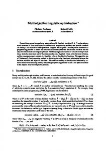
Figure 1: Wavelet-Based Frequency-Subband Analytical Redundancy Scheme. The dashed boxes indicate the wavelet filter bank. In the wavelet filter bank, the number of filtering iterations leading to a given layer is termed
DuiA = (↓ 2)[h ∗ Du(i−1)A ]
(1)
DuiD = (↓ 2)[g ∗ Du(i−1)A ]
(2)
where (↓ 2) and ∗ denote the downsampling and convolution operations, and h and g are the discrete-time impulse responses to filters H and G, respectively. The approximation Du0A at level 0 is equal to signal u itself. Similar equations can be used to obtain the wavelet coefficients DyiA (approximation) and DyiD (detail) of the output signal y. The ARX structure used in (Paiva et al., 2009) is of the form (Ljung, 1999):
Background
In (Paiva et al., 2009), which extended the SISO case in (Paiva et al., 2008) to a MIMO case, a multivariable ARX (autoregressive with external input) structure was adopted for each subband model. Fig. 1 shows the scheme proposed in (Paiva et al., 2009) for an input-output scheme, which can be easily extended for an output-output scheme by replacing plant input u and plant output y by two plant outputs yb and ya . Filters H and G indicate the low-pass and high-pass filters associated to a particular wavelet, respectively. disturbances
the decomposition level of the layer. In Fig. 1, e.g., the filter bank has three decomposition levels. The best decomposition level for fault detection depends on the spectral signature of the fault, as well as the power spectrum density of the input signal and the signal-to-noise ratio of the measurements (Paiva et al., 2008). If the fault effect has not been previously characterized, all levels should be monitored simultaneously. The outputs of the low-pass and high-pass filters are termed approximation and detail, respectively. Subscripts iA and iD are used to indicate the approximation and detail at the i -th decomposition level, respectively. The wavelet coefficients DuiA (approximation) and DuiD (detail) of the input signal u at the i -th decomposition level, i > 0, are calculated as:
ˆ Dy(k) =
na X i=1
ˆ Ai Dy(k − i) +
nb X
Bi Du(k − i),
i=1 p×m
Ai ∈ Rp×p , Bi ∈ R
(3) ˆ where Du(k) ∈ Rm and Dy(k) ∈ Rp correspond to the input and output of the subband model at time index k. Since each subband model is intended to represent the plant behavior only within a limited band, the orders na and nb can be made small. Matrices Ai and Bi can be identified in order to minimize the 2-norm of the differˆ and the ence between the model predictions Dy wavelet coefficients Dy of the actual plant output. For this purpose, a standard multivariable leastsquares identification method can be employed (Ljung, 1999). Both in (Paiva et al., 2008) and (Paiva et al., 2009) a fixed wavelet was used to adjust the parameters of the models in order to minimize the residue between the output of the system and the predicted output. In (Duarte et al., 2013), the concept of wavelet adaptation was exploited to improve the MIMO method proposed in (Paiva et al., 2009). For that purpose, two approaches were considered. The first approach consisted in optimizing the wavelet filter bank parameters to minimize the residue under nominal operating conditions, i.e., to improve the match between the
plant dynamics and the subband model employed in the detector. The second approach also took into account the effects of the fault, by using a biobjective procedure, minimizing the residue under nominal operating conditions (fault-free) and maximizing it under faulty operating conditions. For both purposes, the wavelet filter bank was parameterized by using a vector of angular parameters θ ∈ Rn as in (Sherlock and Monro, 1988). Those parameters were then optimized in order to minimize the 2-norm of the residue under nominal operating conditions. The bi-objective procedure proposed in (Duarte et al., 2013) was performed by a linear combination of the two objectives cited above. The linear combination permitted a monoobjective treatment to the proposed problem. The present paper also exploits the concept of wavelet adaptation over the proposal of (Paiva et al., 2009) in a bi-objective way, but using multiobjective optimization algorithms. The wavelet procedure identification will be carried out by using multi-objective genetic algorithms (MOGA), (Konak et al., 2006). The use of MOGA allows the analysis of the Pareto frontier and the choice of the point that leads to more sensibility (fault detection) with low false alarm rate. The advantage of using Pareto frontiers is in the fact that the choice of the point to be analyzed could be made by a selection criterion and this criterion could be changed without the needing of computing the Pareto frontier again.
inated by any solution encountered by it. 3
Proposed Method
Let A = (A1 , A2 , ..., Ana ) and B = (B1 , B2 , ..., Bnb ) be the matrices of the ARX model (3) at a certain subband. Given the data set D N = (uN , y N ) of input/output signals acquired under nominal conditions and a wavelet filter bank described by a parameter vector θ ∈ Rn , the model matrices A and B can be identified by minimizing a cost function corresponding to the 2-norm of the vector of residues ˆ eD = (Dy − Dy). In view of the dependence of the resulting matrices with respect to the data set and the filter bank, the cost function will be denoted as J N (A, B, θ; D N ) =
1 eD eT D, 2
(4)
where superscript N is employed to indicate nominal operating conditions. The identification result will be written as AN (θ), B N (θ), where (AN (θ), B N (θ)) =
arg min
J N (A, B, θ; D N ).
A∈Rp×p ,B∈Rp×m
(5)
When the objective is to minimize the residue under nominal operating conditions using the wavelet adaptation, a vector θ ∗N is found in order to minimize a cost function J˜N (θ) so that J˜N (θ ∗N ) = minθ ∈Rn J N (AN (θ), B N (θ), θ; D N ). (6)
2.1
Multi-objective Optimization
A multi-objective optimization (MOO) problem has a different perspective when compared with the one having a single objective. In the singleobjective optimization there is only one global optimum, but in MOO there is a set of solutions, called Pareto-optimal (PO) set, which are considered to be equally important; all of them constitute global optimum solutions (Bandyopadhyay et al., 2008). The MOO can be formally stated as follows (Bandyopadhyay et al., 2008). Find the vectors x ¯∗ = [x∗1 , x∗2 , ..., x∗n ]T of decision variables that simultaneously optimize the M objective values {f1 (¯ x), f2 (¯ x), ..., fM (¯ x)}, while satisfying the constraints, if any. The concept of domination is very important in MOO. In the context of a minimization problem, a solution x ¯i is said to dominate x ¯j if ∀k ∈ 1, 2, ..., M , fk (¯ xi ) ≤ fk (¯ xj ) and ∃k ∈ 1, 2, ..., M , such that fk (¯ xi ) < fk (¯ xj ). Among the set of solutions P , the nondominated set of solutions P 0 are those that are not dominated by any member of the set P . The nondominated set of the entire search space S is the globally PO set. In general, a MOO algorithm usually admits a set of solutions that are not dom-
On the other hand, in order to increase the detector sensitivity with respect to the fault, it may be convenient to adjust θ to maximize the residue under faulty conditions, i.e., to maximize a cost function J˜F (θ) so that J˜F (θ ∗F ) = maxθ ∈Rn J F (AN (θ), B N (θ), θ; D F ), (7)
where the superscript F indicates faulty operating conditions. In order to aggregate (6) and (7), i.e., to achieve a compromise between minimizing the residue under nominal operating conditions and maximizing it under faulty conditions, the following bi-objective cost function should be minimized J˜N F (θ ∗N F ) = minθ ∈Rn [J N (θ), −J F (θ)].
(8)
For a better graphical visualization of the plots of J N × J F , (8) can be written in terms of log10 (J N (θ)) and log10 (J F (θ)), leading to (9). J˜N F (θ ∗N F ) = minθ ∈Rn [log10 (J N (θ)), −log10 (J F (θ))]. (9)
In this paper, (9) will be adopted. It is worth noting that the formulation presented here is the same presented in (Duarte
et al., 2013). But now, differently from the proposal of (Duarte et al., 2013) the wavelet identification procedure takes place directly using (9), instead of a linear combination of the two objectives in (8). This approach enables the choice of a point in the Pareto frontier, the one that best matches better sensibility and low false alarm rates. 4
Application Example
In order to test the proposed method, a simulation model of the lateral dynamics of a Boeing 747 aircraft in landing configuration (Bryson, 1985) was used. This simulation model can be written as v˙ pr˙˙ φ˙
"−0.089 =
" 0 +
−2.19 −0.217 0.327 0.150
0.076 −0.602 0
0.0327 −0.151 0.0636 0
#
0.0264 0.227 0
0.328 −0.166 −0.975 1
h i δa δr
0.319 0 0 0
# "v # r p φ
" 0.089 # + −0.076 0.602 d 0
(10) where v is the sideslip velocity, r is the yaw rate, p is the roll rate, φ is the roll angle, δa is the aileron angle, δr is the rudder angle, and d is an exogenous disturbance (lateral wind velocity). The adopted units are feet, seconds, and crad (0.01 rad). The system is operated under a control law of the form " # h i h i v δa −4.15 7.6 5.36 5.57 r (11) δr = − 3.43 −14.24 0.62 −0.24 p φ
which places the closed-loop poles at −2, −1 and −1 ± 2j (Paiva et al., 2008). Each measured state is assumed to be corrupted by an additive white noise with a standard deviation equal to 2% of the standard deviation of the true signal. The disturbance d was generated as a low-pass-filtered Gaussian noise with a standard deviation of 10 ft/s. The problem consists of detecting a gain reduction in the rate gyro responsible for measuring the yaw rate r. Fig. 2 presents an example of a fault at tf = 100 s. Training and test signals were acquired with a sampling frequency fs = 100 Hz. 0
-1 0 0.2
20
40
60
80
100
120
140
160
180
200
20
40
60
80
100
120
140
160
180
200
20
40
60
80
100
120
140
160
180
200
20
40
60
80
100
120
140
160
180
200
20
40
60
80
100
120
140
160
180
200
20
40
60
80
100 t(s)
120
140
160
180
200
0 -0.2 0 0.5 0 -0.5 0 1
δr (deg)
δa (deg)
φ (deg)
p (deg/s)
r (deg/s)
v (ft/s)
1
0 -1 0 5 0 -5 0 2 0 -2 0
Figure 2: Simulation of the 747 aircraft model with a fault at tf = 100 s (angles in degrees).
5
Fault Detection Results
In order to apply the proposed fault detection method, the db8 wavelet filters (Daubechies, 1992) were used as a starting point for the optimization procedure. The choice for these filters was based on the results presented in (Paiva et al., 2008), (Paiva et al., 2009) and (Duarte et al., 2013). The optimization process for MOGA was carried out by a MATLAB implementation as R in the MATLAB Global Optimization Toolbox. In this work, the detection threshold was fixed as four times the standard deviation of the residue in nominal operating conditions. For fault detection, as in (Paiva et al., 2009), the overall fault monitor, in Fig. 1, declared a fault if any threshold detector was activated. In the aircraft simulation, the proposed wavelet method was applied to check the consistency between sensors using SISO and MIMO approaches. For the SISO approach, consistencies between sensors (p, r) and (φ, r) were checked. In those cases, in Fig. 1, y = r and u = p or u = φ. For the MIMO approach, consistency between sensors (p, φ) and r was checked. Now, in Fig. 1, u = [p φ]T and y = r. Three wavelet decomposition levels were used in the wavelet filter banks. The ARX orders were the same adopted in (Paiva et al., 2009) for each subband model, namely which will be na = 1 and nb = 2. For the three consistency checks, Pareto frontiers were generated for each wavelet decomposition level. Fig. 3 shows the Pareto frontiers for the three consistency checks. Observing Fig. 3, it is possible to note that, in each wavelet decomposition level, the point that best comprises the minimization of J N and the maximization of J F is the one that maximizes the distance of the green diagonal line. The choice for this point provides J N