towards all-IP mobile networks, with the IP Multimedia. Subsystem (IMS) being the ultimate approach for future wireless services. However, due to the complexity ...
Multi-Protocol Profiles to Support User Mobility Across Network Technologies Oliver Haase, Ming Xiong, Kazutaka Murakami Bell Labs Research, Lucent Technologies {oli,mxiong,kmurakami}@bell-labs.com Abstract Seamless roaming in heterogeneous circuit-switched and IP networks is key for successful migration towards all-IP. The Unified Mobility Manager (UMM) keeps track of users’ locations whatever network they are roaming, and that routes calls from any originating to any terminating network. In a UMM enabled network, calls are addressed to users and dynamically routed to the active devices. This notion of user mobility breaks up the traditional coupling of addresses and devices, and replaces it with rules for the dynamic mapping from logical to device addresses. We present the UMM multiprotocol subscriber base that is built upon the concept of Incoming Call Handling (ICH) profiles that are the addressable entities in the UMM. An ICH profile contains all address level service data as well as the routing rules to the actual terminating devices. We also present our implementation of the UMM subscriber base in detail, and compare the UMM approach with two other approaches – a federated approach and an approach that combines ANSI-41 user mobility with GAIT interworking. I. INTRODUCTION The wireless communications industry is headed towards all-IP mobile networks, with the IP Multimedia Subsystem (IMS) being the ultimate approach for future wireless services. However, due to the complexity of the task and the recent economical downturn, it will take several years to wholly deploy all-IP mobile networks, especially in the access networks due to their large coverage area. During the transition period from circuitswitched to all-IP mobile networks, multiple types of network technologies will coexist and need to interoperate. The rapid deployment of WiFi networks further increases the degree of network heterogeneity. At the same time, IP voice service is becoming prevailing in wireline networks, and IP enabled mobile backbone networks (core IP networks) are becoming a reality. The Session Initiation Protocol (SIP) is the most popular signaling protocol for Internet telephony and has also been adopted for IMS. The IMS is a special instantiation of the SIP framework, in that the roles of various call control and service execution servers are clearly defined, and interfaces that are unspecified in SIP have been specified for the IMS architecture. As a result, SIP based wireline networks,
voice over WiFi networks, and all-IP mobile networks can vary significantly, especially in the way location management and service invocation is performed. In the near future, core networks will be circuit switched or IP based, and the protocols used will be traditional cellular protocols such as GSM, UMTS, ANSI41, or SIP for IMS based architectures. Access networks will comprise traditional cellular networks, such as GSM, UMTS, or CDMA / AMPS networks, WiFi networks, IMS networks, or even wireline networks such as PSTN and Internet. In such a heterogeneous environment, the support of seamless roaming across network technologies becomes key to the successful evolution towards all-IP mobile networks. The use of multi-mode phones operating on multiple protocols only partially solves the issue. It can support connectivity across protocols using a single terminal (terminal mobility). Complementarily, intertechnology location management in the core networks is needed in order to keep track of what network the device is currently roaming in and where it is located. However, the availability of such multi-mode devices is still fairly limited. This limitation can be overcome with the introduction of a user mobility infrastructure. User mobility enables users to switch between end devices and still get the same, personal services. These services include the access to one's personal service data, the availability of a personal collection of customized services, and, above all, call and message delivery to a user at the same user address regardless of the network the user is currently roaming in. User mobility requires breaking up the traditional mto-1 address-to-terminal relationship in cellular networks, which forces an address to belong to one single terminal. The new infrastructure must allow for a more general mto-n relationship between addresses and terminals. The infrastructure must be able to intercept a call to a user address and dynamically map the user address to one or several devices belonging to the addressed user. The Unified Mobility Manger, UMM, [3] [4] integrates mobility management functions of multiple network protocols in one logical entity, and adds user mobility capability on top of it. The UMM provides traditional cellular networks with standard Home Location Register (HLR) functionality, maintaining the registration and location information of the mobile terminal and the value
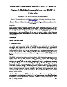
added service settings. For SIP networks, it works as a SIP location manager, maintaining the user’s contact addresses together with related service subscriptions. Through protocol interworking, the UMM further facilitates user mobility across network technologies. This paper describes the UMM multi-technology subscriber base where users can own several (fixed wired and wireless) devices of diverse technologies, each of which can be used to terminate incoming user level calls. Thus, a user can transparently roam across network technologies, while still being reachable at the same user address. The concept of an Incoming Call Handling (ICH) profile is introduced to model many-to-many address-toterminal relationships across technologies, while terminal level profiles store traditional terminal specific service data. The ICH profile allows a user to have appearances in multiple networks, which eliminates unnecessary signal translation in heterogeneous network environments [3]. II. UMM: UNIFIED MOBILITY MANAGER The UMM [3] [4] combines mobility management, security management and unified user profile management for various mobile networks, including traditional cellular protocols (e.g. GSM, ANSI-41), 3rd generation wireless networks (e.g. UMTS, cdma2000), as well as Internet telephony networks (e.g. SIP) in one logical entity. Figure 1depicts the structure of the UMM. It consists of a multiprotocol subscriber base, a core logic server, and a set of protocol gateways (PG), one per network technology. A PG is employed to accept the respective protocol’s mobility management messages, such as UMTS Mobile Application Part (MAP), ANSI-41, and SIP. The core logic server performs service logic such as registration and call/message delivery, which potentially leads to protocol interworking across network technologies. U M M
U s e r P r o file A N S I4 1 te r m in a l (o n a t M SC X)
U M TS te r m in a l (o n a t M SC Y)
S IP te rm in a l (o ff)
M u lti- P r o to c o l S u b s c rib e r B a s e
C o r e L o g ic S e r v e r A N S I4 1 PG
A N S I4 1 N e tw o rk
Figure 1.
U M TS PG
UM TS N e tw o rk
S IP PG
S IP N e tw o rk
Unified Mobility Manager
The UMM acts like a native mobility management entity from the viewpoint of each network, even though it supports multiple network protocols. A UMTS network, e.g., views it as a UMTS HLR, while it works like a combination of SIP registrar and SIP proxy server from the SIP viewpoint. Thus, the UMM receives all registration and location resolution requests of the
networks it is responsible for. Consequently, the UMM multi-protocol subscriber base stores the location information for all terminals a user owns. Taking advantage of this combined information about multiple networks, the UMM can transparently provide user addressing and mobility, without requiring any changes in other network elements, such as Mobile Switching Centers (MSC) or SIP servers and user agents. III. MULTI PROTOCOL USER PROFILES The UMM subscriber base is built upon the concept of users who owns n (n≥1) terminals in various networks. Addresses, i.e. phone numbers and SIP URLs, are assigned to users and dynamically mapped to one or several terminating devices in the event of an incoming call request. A user owns m (m≥1) user level addresses, each of which is assigned to a different set of service settings and a different destination selection policy. Figure 2 illustrates a typical user profile in the UMM multi-protocol subscriber base. The concept of an Incoming call handling service profile, or ICH profile in short, is introduced to realize a user level address with a distinct service setting. Each user level address is associated with a particular ICH profile that determines the call set-up behavior for this address. A user may, e.g., have a rather protective ICH profile (all calls between 6pm and 8am are routed to the voice mail) for public use, another, more relaxed ICH profile (evening calls are routed to the home landline phone) for their colleagues, and one for private use (all incoming calls are routed to the user’s cell phone). The address associated with the public ICH profile would be listed in the white pages, the address for the second ICH profile would be listed in a corporate phone book, and the address of the private ICH profile would only be privately distributed. As shown in Figure 2, each ICH profile can have multiple addresses, to make it callable from various originating technologies, such as circuit-switched and Internet-based. The ICH profile is the only addressable entity in our system. Traditional terminal addresses are modeled as ICH profiles that point to exactly one terminal. A. Address Level Service Data The ICH profile is the entity that hosts all address level service data, and that models the m-to-n relationships between addresses and devices. We differentiate two categories of address level services: (1) services that only depend on the called address but not on the actual terminating device(s), and (2) services that depend on both. The former set is modeled in Network-A-Profiles (AProfiles), while the latter set is captured in Network-BProfiles (B-Profiles). The names reflect the networks these services depend on, in ANSI-41 terminology. If a call, e.g., is addressed to a UMTS address, but is delivered to an ANSI-41 network, then UMTS is Network A and ANSI-41 is Network B.
The ICH profile must contain exactly one protocol specific A-Profile per network technology that it has an address for – e.g. one UMTS A-Profile if it has at least one UMTS phone number associated. As explained before, an ICH profile can have multiple addresses belonging to different network technologies. This way, it is directly callable from various originating networks without the need for signaling and media conversion before the UMM can be interrogated for address resolution. A-Profile information is protocol specific as the information is returned to the interrogating network entity in the originating network, e.g. a UMTS Gateway MSC, or an ANSI-41 Home MSC, and these entities expect the service data in the appropriate format. Every B-Profile defines services whose settings are specific to one particular (ICH service profile, terminal) combination. As every terminal belongs to a certain technology, B-Profiles are protocol specific. B-Profiles are the most fine-grained modeling unit for service data, as every possible (ICH profile, terminal) combination can be configured separately. In every ICH profile, there is exactly one B-Profile per potential terminating device. B. Terminal Level Service Data With our system, we still have the concept of terminal level information, such as the current location and roaming restrictions for terminal registration. Terminal level information is specific to the physical device and independent of any callable address. Obviously, terminal information is not stored in the ICH service profiles, but ICH service profiles point to terminal level information. C. Service Decomposition into Different Profiles User Profile
User Info
ICH m
Terminal profile n
ICH 2
ICH 1 DN 3 DN 2 URL 1
Figure 2.
DSP ANSI41 A-profile UMTS A-profile SIP A-profile
ANSI41 B-profile UMTS B-profile SIP B-profile
Terminal profile 3. ANSI41 Terminal profile 2. UMTS Terminal profile 1. SIP
A user profile in UMM subscriber base
As described, our new mobile subscriber data model decomposes the traditional subscriber service data into A-, B-, and terminal profiles. The design of this service decomposition will influence how the service is performed when a call request covers multiple protocols. Suppose, e.g., a call originates from a UMTS network using a UMTS directory number. Further suppose the callee is currently roaming only in an ANSI-41 network. In this scenario, if a certain service is modeled in the A-Profile, the UMTS A-Profile setting determines service invocation.
If the same service is modeled in the B- or the terminal profile, however, the service is invoked based on the ANSI41 B- or terminal profile, respectively. Note that the service decomposition has no impact on ICH profiles that relate to a single protocol and a single terminal only. In general, service decomposition is a matter of design. However, some service categorization is rather obvious from the nature of the service. For example, the various flavors of call forwarding, such as call forwarding unconditional, call forwarding on busy, etc., ought to be in the A-Profile since it does not make sense to have different call forwarding on busy numbers per terminal for the same address. Instead, the service should be defined uniformly per address. Some service data that depends on the location of a terminal (e.g. call baring when roaming out of a home network) must be defined in the terminal profile. Actually, the majority of traditional mobile services shall belong to the terminal profile since most existing cellular services are protocol-specific and are not designed with the separation of addresses and terminals in mind. In order to further set different service setting per address, the service can be moved from terminal Profile to B-Profile. For example, if the ‘do not disturb’ feature is defined in the B-Profile, all incoming calls to a personal cellular phone except for calls addressed to the number only known by family members can be rejected. D. Destination Selection Policies In order to choose the destination when more than one related terminal is available to receive a call, the ICH service profile employs a destination selection policy (DSP). The DSP is a collection of rules which is evaluated at the time of an incoming call request, and that returns one or multiple termination devices that are to be alerted serially with prioritized order, in parallel, or in a mixed fashion. Possible criteria in the condition part of a DSP are time of the day, caller ID, subscriber’s roaming status, originating network type, terminating network type, current location, roaming restrictions, terminal registration timestamp, and terminal capabilities. IV. IMPLEMENTATION OF THE UMM SUBSCRIBER BASE We have built a UMM prototype system and measured the performance of the UMM subscriber base system. The system comprises a set of SUN Netra 1440 workstations connected via 100Mbps Ethernet, with each consisting of 4 440MHz UltraSPARC-II processors with 4GB RAM. To support the requirement on extremely short response time on the order of milliseconds, a high performance, main memory database is used for the UMM subscriber base to avoid disk based data retrieval. The UMM is deployed on a distributed architecture to ensure that there is no single bottleneck in the system. In order to promote system scalability and reliability, the UMM components are deployed into two separate functional processes, the logic server and the database
ANSI-41 HLR
1. IAM
3. ROUTEREQ
IIF
min2 = imsi imsi: MSC2
6. TLDN = b 7. TLDN = a, b
Alice (212-555-7777) min1: MSC1 min2: IIF
ANSI-41 home MSC
Figure 3.
b
We have conducted experiments on our UMM system with 1 million subscribers in each UMM subscriber base. The results are shown in Table 1. The UMM subscriber base aims at supporting 640 transactions per second. In our experiments, we use workloads similar to what are generated from UMTS MAP messages, and 50% of workloads are update transactions. We also scale the number of subscribers on each site and observe that the impact on performance is minimal because of the use of main memory database indexes. Our experimental results
4. TLDN = a
= RN MS
Table 1. UMM average response time (RT)
3. ROUTEREQ
9. alert
N PR
RT 1368 us 3270 us
ANSI-41 MSC1
4.
Type of request Subscriber data retrieval for call delivery Location data update
A. GAIT IIF with ANSI-41 User Mobility An Interworking and Interoperability Function (IIF) as defined in the GSM/ANSI-136 Interoperability Team (GAIT) standard [8] provides GSM/ANSI protocol mapping function so that an existing ANSI41 HLR can be easily extended to accommodate GSM handsets. The ANSI-41 flexible alerting (FA) and multiple access hunting (MAH) features [2] further allow to route a call to multiple ANSI-41 devices either in parallel or serially. If the ANSI-41 FA and MAH are combined with GAIT, a restricted version of user mobility can be supported for ANSI41 and GSM devices. Figure 3 shows the system structure and a sample call set-up scenario of this approach.
5.
Due to subscriber data partition, logic servers need to know which database server contains relevant data for a request. We introduced an index mechanism to each logic server for this purpose. It determines to which server a subscriber data request is routed according to the subscriber’s keys, which may be terminal identifier (e.g., IMSI or MIN), directory number, or SIP URL. The index is built in a B-Tree on each logic server, and it is constructed at system initiation time by downloading subscriber key range partitioning information from the subscriber base. Whenever information of a subscriber is migrated from one subscriber base to another, the corresponding key information on each index is updated so that requests for the subscriber are routed to the right database server.
V. COMPARISON WITH ALTERNATIVE APPROACHES The proposed approach with the UMM is only one of several thinkable solutions for a multi-protocol, user mobility infrastructure. This section briefly sketches two essentially different, but promising approaches [8] [9]. Then, we compare these approaches with the UMM in terms of signaling load and performance, data consistency, as well as platform maintenance.
2. LOCREQ
To reduce the number of inter-server communication, all necessary data to handle a mobility management request (e.g. call delivery) is downloaded to a logic server at once. This data is separated into A-, B- and terminal profiles, but stored together for a single subscriber. To avoid unnecessary message exchanges, the UMM subscriber service data is “horizontally” partitioned across multiple database servers, i.e., they are partitioned based on subscribers and data per subscriber is always stored on the same pair of servers. This allows any DB lookup per subscriber to be satisfied by querying local databases.
validate that our UMM subscriber base is a highperformance data repository for mobile subscribers.
8. IAM (a)
server. The logic server hosts PGs and core logic server functions and takes N+k configuration to accommodate a large volume of requests with high availability. On the other hand, the database server accommodates UMM multi-protocol subscriber base. Multiple database servers can be deployed to increase the system capacity with balanced workload. Each server takes a mated pair configuration so that the subscriber data is always replicated to its peer to improve reliability. This also avoids the single point of failure problem. Each site of the mated pair can act as a primary site, and updates are propagated after transactions commit. It depends on the database to resolve conflicting requests from transactions for consistency of data.
8. IAM (b)
9. alert GSM MSC2
GAIT Approach
In the example, Alice’s personal phone number, 212555-7777, technically has to be an ANSI-41 mobile number. This makes an incoming call be routed to the ANSI-41 home MSC (1), that interrogates the ANSI-41 HLR for location information (2). As the phone number, 212-555-7777, turns out to be a flexible alerting number, it is mapped to two devices, min1 and min2. As ANSI-41 device min1 is currently served by MSC, MSC1, the HLR requests routing information from this serving MSC and obtain an ANSI41 temporary routing number, TLDN a (upper part of 3, 4). The serving MSC of device min2, however, is indicated as IIF. Consequently, the ANSI-41 HLR requests routing information from the IIF. The key enabling mechanism of GAIT approach is that IIF simulates a serving MSC to the ANSI-41 network, while it appears to a GSM HLR to the GSM network. The IIF maps the ANSI
device ID, min2, to a GSM device ID, imsi, looks up the current serving MSC, and interrogates it for routing information (4). The resulting information, MSRN b, (5) is converted to an ANSI-41 TLDN and returned to the ANSI-41 HLR (6). The ANSI-41 HLR returns both TLDN numbers, a and b, back to the home MSC (7). The home MSC can now set up two parallel call requests to the ANSI and the GSM mobile (8, 9). With this approach, subscriber data is split across the ANSI-41 HLR and the IIF. The ANSI-41 HLR stores both the user level service data including the mapping from user to terminal address, and the ANSI-41 terminal level subscriber data. GSM terminal level data is stored in the IIF, which acts as a GSM HLR B. Federated Approach This approach builds a user mobility (UM) component on top of a federation of existing HLR subscriber bases [9]. Existing HLRs maintains all terminal level information including location information, while a new UM component stores the mapping from a user to terminal addresses. It interrogates the HLRs for terminal availability information so as to make an educated destination selection decision. Figure 4 depicts the system structure and a sample call set-up using this approach. 1. IAM
6. I
AM
IN enabled Switch
7. SRI UMTS Gateway MSC
2. number mapping request (212-555-7777) 5. 908-987-6543 il. va tA d Ge ere 3. ist reg . 4 UMTS HLR
10. MSRN =a 8. PRN
Alice (212-555-7777) UMTS: 908-987-6543 ANSI: 732-123-4567
UM
3. G
4.
et Av ail .
of
f
ANSI-41 HLR
908-987-6543: MSC2 732-123-4567: off 9. MSRN = a
11. IAM (a)
12. alert UMTS MSC2
Figure 4.
Federated Approach
In this example, a call request to Alice’s personal phone number, 212-555-7777, arrives at an Intelligent Networks (IN) enabled switch (1) [10], which triggers a number mapping request to the user mobility component (2). The UM component maps the user address to all associated terminal addresses, in this case one UMTS and one ANSI-41 phone number, and interrogates the respective HLRs for these phones’ availability (3, 4). This step requires the involved HLRs to implement an open interface to do so, such as, e.g., the 3GPP Presence and Availability Management (PAM) interface. In the sketched scenario, we assume that the UMTS phone is currently registered but the ANSI phone is switched off. Note that different from ANSI41 home MSC in GAIT approach, IN enabled switch typically does not support forking, and thus one destination must be selected with this approach even if more than one is available. Equipped with the availability information for the potential destination devices, the UM component makes an educated destination selection
decision, selecting the available UMTS phone. The UMTS phone number is returned to the IN enabled switch (5) that routes the call to a UMTS gateway MSC (6). The gateway MSC sends a Send Routing Information (SRI) message to the UMTS HLR (7), which interrogates the serving MSC for an MSRN (8). The MSRN is returned to the HLR (9) and passed backed to the gateway MSC (10). Finally, the call is routed to the serving MSC (11) and the mobile phone gets alerted (12). With the federated approach, the multi-protocol subscriber data is split across several components: The mapping information from user to terminal addresses resides in the UM component, while the terminal level information for the various network technologies of a user is vertically partitioned across technologies, i.e., technology specific terminal level information only lives in the respective location managers. Address level services, such as call forwarding per called address, are not supported in the federated approach, as these services are executed in the terminal level network entities. C. Comparison In the following, we compare the three approaches from different aspects. Signaling load and performance: As in the UMM the address mapping information is stored together with the location information for various technologies, the signaling effort to set up a call is minimal. In the federated approach, on the other hand, the user mobility component first interrogates the location managers of all potential destination devices for availability information, and later the location managers of the actually selected devices are revisited for routing information. The GAIT based approach ranges in the middle; it is similar to the UMM for ANSI-41 devices, but needs to go through the IIF to get location information for UMTS devices. Table 2 summarizes performance numbers of signaling messages and database accesses for each approach in the case of call delivery to an ANSI41 user address. The variables Nall, Nact, and Ndif denote the number of terminals the user owns, the number of currently active terminals, and the number of active, non-ANSI-41 terminals, respectively. The table also shows in parentheses the numbers for a typical user mobility scenario where Nall=2, Nact=1, and Ndif=1. Table 3 summarizes the same performance numbers for each approach in the case of inter-technology location registration (i.e., roaming from one technology to another). As demonstrated for both call set-up and registration which comprise the major workload for mobility management component - the UMM incurs fewer signaling messages and database operations. Hence, the UMM is expected to outperform the GAIT based as well as the federated approach.
Data consistency: As the UMM subscriber base combines all address and terminal level information in one data model, keeping service data consistent across technologies is straightforward. This is not the case with the two alternative approaches, as with them, each technology’s subscriber data is stored in a separate network entity. To preserve data consistency, distributed transactions that impose significant performance overhead, are required. UMM GAIT Federated
No. of messages 3+4Nact (7) 3+4Nact +2Ndif (9) 3+7Nact +2Nall (14)
No. of DB reads 1 (1) 1+Ndif (2) 1+Nall+Nact (4)
Table 2. Performance for call set-up
UMM GAIT Federated
No. of messages 4 6 8
No. of DB accesses 1 read + 1 write 2 read + 2 write 3 read + 2 write
Table 3. Performance for location registration
Platform maintenance: Another key strength of the UMM is that the carrier needs to maintain only one location management platform, including hardware, database, and provisioning systems. This benefit is very important to reduce the carrier’s long-term operating cost. The federated approach is the worst in this category, as the number of different location managers including the user mobility component is the greatest. VI. CONCLUSION We have presented the UMM subscriber data model for a multi-technology location manager that combines user with terminal mobility. The two main concepts of the UMM subscriber model are the separation of addresses and terminals, and the introduction of address level service data through the ICH service profile. The UMM prototype system adopts the distributed architecture, promoting a highly reliable, scalable system. Horizontal partitioning of the multi-protocol subscriber base results in high performance in the system. Compared to the alternatives, the UMM incurs less signaling load in the mobile backbone network and fewer database operations. Its unified subscriber base eliminates the need of complex and time costly distributed transaction mechanisms to ensure data consistency. In summary, the UMM is the superior technology for the support of user mobility and the migration towards converged all-IP networks. One potential issue, however, is the deployment cost. Subscriber and location management systems are huge investments, and replacing existing ones with new technology is a big step. Thus, for carriers that already have an ANSI-41 HLR, the GAIT approach is attractive as it requires fewer changes to the existing network
equipment. However, this approach establishes ANSI-41 as the "master technology" in the heterogeneous networks, which makes the eventual evolution to all-IP difficult, and even more costly. The federated approach, on the other hand, is a more symmetric approach and thus better suited for the migration to all-IP. However, it assumes the existence of open interfaces at the existing location manager, which is not realistic for virtually all deployed equipment. Also, this approach is worst in almost all technical dimensions. In conclusion, the higher deployment cost for the UMM is over-compensated by the significantly lower maintenance cost in the long run due to its single platform, homogeneous subscriber model, and unified provisioning system. Finally, the issue of data migration from a legacy system to the UMM can be taken care by customized migration tools. REFERENCES rd
[1] 3 Generation Partnership Project, “Technical Specification Group Services and System Aspects; IP Multimedia Subsystem (IMS); Stage 2 (Release 5),” (version 5.5.0), 3GPP TS 23.228, Jun. 2002. [2] ANSI/TIA/EIA-41-D: “Cellular Radiotelecommunications Intersystem Operations”, TR 45.2, Dec. 1997. [3] O.Haase, K.Murakami, and T.F.LaPorta, “Unified Mobility Manager – Enabling Efficient SIP/UMTS Mobile Network Control,” IEEE Wireless Communications Magazine, pp.66-75, Aug. 2003. [4] R.Isukapalli, T.Alexiou, and K.Murakami, “Global Roaming and Personal Mobility with COPS Architecture in SuperDHLR,” Bell Labs Technical Journal, vol.7, no.2, pp.3-18, Nov. 2002. [5] M. Roussopoulos, P. Maniatis, E. Swierk, K. Lai, G. Appenzeller, M. Baker, “Person-level Routing in the Mobile People Architecture,” In Proc. USENIX Symposium on Internet Technologies and Systems, Oct 99. [6] H. J. Wang et al. “ICEBERG: An Internet-core Network Architecture for Integrated Communications”. IEEE Personal Communications Magazine, special issue on IPbased Mobile Telecommunication Networks, 2000. [7] 3rd Generation Partnership Project, “Technical Specification Group Core Network; Support of Optimal Routing (SOR); Technical Realisation (Release 1999),” (version 3.7.0), 3GPP TS 23.079, Jun. 2002. [8] GSM/ANSI-136 Interoperability Team (GAIT), “Network Interworking between GSM MAP and ANSI-41 MAP,” PN-4857, TR-46, Dec. 2000. [9] A.P.Sheth, and J.A.Larson, “Federated Database Systems for Managing Distributed, Heterogeneous, and Autonomous Databases,” ACM Computing Surveys, Vol.22, No.3, pp.183-236, Sep. 1990. [10] T. Magedanz, R. Popescu-Zeletin. Intelligent Networks. International Thomson Publishing, 1996, ISBN 1850322937.