Multi-Stage Interference Cancellation in Multi-Rate DS/CDMA Systems* Ann-Louise Johansson and Arne Svensson Chalmers University of Technology Department of Information Theory S-412 96 Gothenburg, Sweden
[email protected]/
[email protected]
ABSTRACT We show that the one-stage IC scheme for Mlevel rectangular QAM can easily be extended to a multi-stage IC scheme. The performance of different single modulation systems, with equal throughput, is compared with systems employing conventional detectors and the single user bounds. In the analysis we consider two methods for handling multiple data rates, mixed modulation and parallel channels. These methods are analysed under the assumption of Rayleigh fading. The results show a considerable improvement in both performance, close to the single user bound, and capacity compared with systems employing a conventional detector.
tion are found in [10]-[12] and a work, independent of ours, on a multi-stage successive IC scheme can be found in [13]. Though solely BPSK modulation and Gaussian channel with unequal power control is considered in [13].
1. Introduction
The analysis in [8] and [9] dealt with successive IC schemes, where we ranked the users in decreasing order of their powers and cancelled them successively from the composite baseband signal starting with the strongest user. This we call a one-stage scheme. Without making the scheme considerably more complex we can easily extend it to a multi-stage scheme. A second stage in a two-stage scheme would then operate as follows: The signal of the strongest user, that was cancelled in the first stage, is added to the composite signal and a new estimate of the signal is obtained. Since we have decreased the interference exposed to the user, compared to the first stage, we will improve the performance. We then cancel the signal again and continue doing the same for the next strongest user and so forth.
In the future there will be a need for mobile telephone systems to handle all kinds of services besides speech. This will demand the systems to be able to handle multiple data rates. Other important issues for the systems are low bit error rate (BER) and high capacity. A multiple-access method suitable for such a system is believed to be Direct Sequence Code Division Multiple Access (DS/CDMA). If we employ a conventional matched filter detector in a DS/ CDMA system it will be interference limited. This is because the spreading codes are not completely orthogonal and therefore introduces multiple-access interference (MAI). A conventional detector is optimal if the signal is corrupted only by AWGN and even when the cross-correlation between the codes is low the interference could become devastating if the interferer is very strong. This is known as the near/far problem. This problem may be reduced by using stringent power control [1], though it is difficult to perform power control for the fast fading. Anyway, the system will still be interference limited, since there are not any codes with good cross-correlation properties for all shifts. The solution may then be found in a more sophisticated detector than the conventional detector. A lot of work has been done on suboptimum multiuser detectors where some kind of interference cancellation (IC) is used, both using parallel [2]-[4] and successive [5]-[9] detection. In this paper we concentrate on a multi-stage successive IC scheme based on the idea in [5], [6]. Multi-stage schemes with parallel detec-
In [8] and [9] we have analysed different methods to handle multiple data rates in a DS/CDMA system. One way to do this is to use mixed modulation formats. A user can then choose between e.g. BPSK, QPSK, 16-QAM modulation depending on the need. Another way to handle multiple data rates is to let each user transmit over one or several parallel channels according to requirements.
In the sequel we will define the system model and give a brief introduction to the one-stage successive IC scheme. Though the emphasis is on the analysis of the multi-stage schemes and the performance of mixed modulation and parallel channel systems. We will show that a considerable increase in both capacity and performance is obtained. We will consider the coherent case of demodulation and frequency-nonselective fading. The performance measure used is average bit error probability. We assume perfect knowledge of the phase and the time delay. We also assume perfect power ranking in the performance analysis, which implies knowledge of the channel gain. This knowledge is however not used in the IC scheme itself.
2. System Model * This research was supported by the Swedish National Board of Industrial Technical Development, NUTEK. Project 9303363-2.
We consider a system model for a system utilizing square lattice QAM, where the received signal, for a K user system, is
the sum of all the transmitted signals embedded in AWGN with two-sided power spectral density of N 0 ⁄ 2 . r ( t) =
K
∑ αk k=1
αk
2E 0 I --------- d kI ( t – τ k ) c k ( t – τ k ) cos ( ω c t + φ k ) + T 2E 0 Q --------- d kQ ( t – τ k ) c k ( t – τ k ) sin ( ω c t + φ k ) + n ( t ) T
cos ω c t
(1)
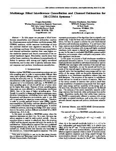
The information-bearing signal for all the users is an infinite sequence of A kI ,/ Q l amplitude, rectangular pulses of duration T. is the amplitude of the quadrature carriers for the k th A kI ,/ Q l th user’s l symbol element, which together generate M equiprobable and independent symbols. Each user, k, has two signature sequence, c kI / Q ( t ), which are used for spreading the signal in the in-phase (I) and the quadrature (Q) branch. They consist of a sequences of, antipodal, unit amplitude, rectangular pulses of duration T c . The period of all the users’ signature sequences is N = T ⁄ Tc , so there is one period per data symbol. In the asynchronous, though symbol-synchronous, case the time delay, τ k , and the phase, φ k , are i.i.d. uniform random variables over [ 0, T ) and [ 0, 2π ), respectively. Both parameters are assumed to be known. Additionally the amplitude of the signal is affected by the channel gain, α k . Figure 1 shows the structure of the k th user’s receiver. The Ibranch as well as the Q-branch is correlated with both the I and Q signature sequences of the k th user to form four different Z k, l factors at each instant of T. These factors, which contain all information, are then used to form the decision variables, S kI , l and S kQ, l , which are the sufficient statistics. S kI ,/ Q l consists of one constant, the symbol amplitude, and noise components, which before the first cancellation consists of Gaussian noise and MAI.
3. Multi-Rate Schemes with One-Stage Interference Cancellation A block diagram of a one-stage receiver with IC, analysed in [8], [9], is shown in Figure 2. First the users are ranked in decreasing order of their powers. Without loss of generality we assume that user 1 has the strongest signal, user 2 has the second strongest and so forth and that we consider the decision of symbol element 0. Accordingly, we then decode the zeroth c kI ( t – τ k ) cos φ k SI Z II + 1 cos ω c t --- ∫ dt k, l + k, l Decision Device T δI ( t) Q – c k ( t – τ k ) sin φ k LPF IQ 1 --- ∫ dt Z k, l ( )2 T ( S k, l ) 2 r ( t) c kI ( t – τ k ) sin φ k + 1 2 --- ∫ dt Z QI ( ) k, l T δQ ( t) Q c k ( t – τ k ) cos φ k LPF + SQ Z QQ 1 --- ∫ dt k, l + k, l Decision Device sin ω c t + T
Figure 1 M-ary QAM DS/CDMA receiver
LPF
δI ( t) – ++
r ( t)
LPF sin ω c t
c 1Q ( t – τ 1 ) sin φ 1
+
δQ ( t) +
+
–
+
S 1I , 0 Detector
1
Detector
2
S 1Q, 0
c 1I ( t – τ 1 ) cos φ 1 S 1I , 0S 1Q, 0 Select Max & Decode
S KI , 0 Detector K SI SQ S KQ, 0 1, 0 1, 0 c 1I ( t – τ 1 ) ( – sin φ 1 ) c 1Q ( t – τ 1 ) cos φ 1
Figure 2 M-ary QAM receiver with Interference Cancellation
symbol of user 1 first, since this user is the one most likely to be decoded correctly. We use the decision variable, S 1I ,/ Q0 , to estimate the signal of the first user’s zeroth symbol element and then we cancel it from the composite baseband signal. In this way we decrease the amount of interference which the next strongest user is exposed to. We continue the scheme for the second strongest user as well as for the subsequent users. Before the h th cancellation, the decision variable is given by S hI ,/ Q0 =
E0 ------α k A hI ,/ Q0 + N hI/ Q 2T
(2)
where the noise term N hI/ Q includes Gaussian noise, noise caused by imperfect cancellation of stronger users and interference from weaker users. The scheme is repeated until all the users’ symbol element 0 is decoded and cancelled.
4. Multi-Stage Interference Cancellation As described above the decision variable in eq. (2), which is used to estimate the signal, contains noise caused by interference from the other users in the system since the signature sequences are not completely orthogonal. Hence, it is impossible to cancel the signal perfectly and a new noise term is added to the composite signal at each step of the scheme. Though the added noise is much less than the noise caused by interference. The motivation for a multi-stage IC scheme, shown in Figure 3, is to decrease the noise being added in the cancellation. Because even though we start the scheme by detecting the strongest user, using the decision variable 1S 1I ,/ Q0 corresponding to S 1I ,/ Q0 in Figure 2, we introduce a moderate amount of noise in the cancellation, since also that user is affected by the interference from all the other users. Adding extra stages in the IC scheme gives all the users the possibility to take equal advantage of the IC and it improves the estimates of the signals to be cancelled and therefore decreases the noise exposed to I/Q ( t ) , in Figure 3, is the composite baseband sigthe users. iδ nal which after a complete first stage of the IC scheme exclusively consists of noise terms caused by imperfect cancellation.
c kQ ( t – τ k ) sin φ k
+ + + δ ( t) + – +
i I
Detector Detector
c kI ( t – τ k ) i I S 1, l i–1 i i–1 i S kI , l S kI , l S kQ, l S kQ, l 1i signal S 1Q, l 1. Add iest. –1 using S kI ,/ Q 2 l i I S K, l
i Q
δ ( t)
Detector Ki
+ +– +
S KQ, l
cos φ k
2. Sub. est. signal i using S kI ,/ Q i–1 I i I i–1 lQ i Q S k, l S k, l S k, l S k, l c kI
+ +
First we calculate the variance of the I and Q channel decision variables conditioned on α k , i.e.
( t – τ k ) ( – sin φ k
c kQ ( t
– τ k ) cos φ k
Figure 3 Multi-stage Interference Canceller
In the second stage of a multi-stage scheme the signal of the strongest user, which was cancelled first in the previous stage, is added again and a new better estimate of the signal is 2 obtained with the help of S 1I ,/ Q0 . That is, when we add the firststage estimate of the signal we remove the noise caused by imperfect cancellation of that signal. Now the baseband signal consists only of the desired signal, Gaussian noise and noise caused by imperfect cancellation and the new second-stage estimate will have smaller variance than the first-stage estimate. Therefore the second cancellation is better and in this way we can improve the performance. Consequently, at each step of the scheme the second-stage estimate of the previously detected signal is cancelled and the first-stage estimate of one user’s signal is added. Therefore the resulting baseband signal of the I branch after the h th cancellation is 2 I δh, 0 ( t )
2 I
2
2
= δh – 1, 0 ( t ) – S hI , 0 a hI – S hQ, 0 a hQ + 1 I S h + 1, 0 a hI + 1
1
(3)
+ S hQ+ 1, 0 a hQ+ 1
where = pT ( t – – τ h ) cos/ sin φ h and p T ( t ) is a unit amplitude, rectangular pulse of length T. If we would like to improve the performance further we could add another stage to the scheme, which would follow the same procedure as described above. a hI/ Q
tem. Instead the interference will only be due to Gaussian noise and resulting noise after the cancellation of the other users. These noise components is of the same magnitude, even if we consider a channel under Rayleigh fading, and the Gaussian approximation should therefore work well. We assume that the users are perfectly power ranked and that we know the decision boundaries for the 16-QAM users. This implies that each user is perfectly tracked, that is, the phase, φ k , and channel gain, α k , is perfectly estimated.
τ h ) c hI/ Q ( t
5. Performance Analysis of a Multi-Stage Scheme In the one-stage scheme the users are cancelled successively and the noise exposed to each user is composed of Gaussian noise, noise caused by imperfect cancellation of stronger users and noise introduced by interference from weaker users. The performance of such a system is analysed in [8], [9]. In the case of multi-stage IC schemes the interference is not directly connected to the powers of the other users in the sys-
η hI/ Q = Var
1N I / Q h
αh
(4)
where the noise, 1NhI / Q , contains of a sum of independent random variables with zero mean. We will analyse the performance of systems where the signals are received through independent frequency-nonselective slowly fading channels. We assume the amplitudes to be Rayleigh distributed and that the average power received from each user is equal, which corresponds to perfect power control for distance attenuation and shadowing. When using the Gaussian approximation it is easy to obtain the probability of error from the theory of single transmission of QAM signals over an AWGN channel [14]. The symbol error rate with ideal coherent detection can be expressed as (5) Pˆ e h = 1 – ( 1 – Pˆ e hI ) ( 1 – Pˆ e hQ ) where Pˆ e hI/ Q is the error probability in the I or Q channel. We obtain the distributions of the ordered amplitudes by using order statistics [10]. Then the unconditional error probability for each stage of cancellation is obtained from the conditional probability of error as follows Pˆ e hI/ Q =
∞
∫ PehI/ Q fα 0
h
( x ) dx
(6)
where f α ( x ) is the distribution of the h th strongest user’s h amplitude and PehI/ Q is that user’s conditional probability of error for the transmission over the I channel, respectively the Q channel, given by [14] M–1 PehI/ Q = 2 ------------------ Q ρ hI/ Q M
(7)
where the Q-function is the complementary Gaussian error function. ρ hI/ Q in eq. (7) is a signal-to-noise ratio for the I or Q channel defined as
ρ hI/ Q
E0 ------α h 2T = ------------------------------E α η hI/ Q
(8)
k
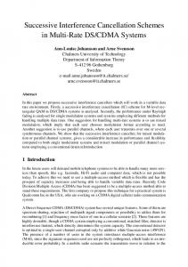
where E α η hI/ Q is the expected value of the conditional vark iance with respect to α k [8]. The performance of three different single modulation systems under Rayleigh fading with the same throughput, 40 BPSK, 20 QPSK and 10 16-QAM are shown in Figure 4 together with the single BPSK and the single 16-QAM user bounds. The code length is 127. The graph
0
0
10
Processing Gain = 127 Random Sequences
Average Bit Error Probability
Average Bit Error Probability
10
−1
10
Conv
−2
10
−3
10
IC 1
BPSK (40) QPSK (20) 16−QAM (10) Single BPSK Single 16−QAM
IC 2
0
−1
10
Mix Conv
−2
10
IC 1
−3
10
Av. BPSK Av. QPSK Av. 16−QAM Mix (20/10/5) Single BPSK
IC 2
−4
−4
10
Processing Gain = 127 Random Sequences
10
5
10
15 20 Eb /N0 (dB)
25
30
0
35
5
10
15 20 Eb /N0 (dB)
25
30
Figure 4 Average BER for single modulation systems with and without multi-stage IC under fading.
Figure 5 Average BER for a mixed modulation system (35 users) with and without multi-stage IC under fading.
depicts three sets of curves, each set corresponding to the use of a conventional detector, a one-stage interference canceller (IC) respectively a two-stage IC. The one-stage IC shows considerable decrease in average BER compared to the conventional detector. The two-stage IC decreases the BER even further and eliminates almost all the interference in the systems. The curves follow closely the single BPSK and single 16-QAM user bound up to about 30 dB E b ⁄ N 0 , where the curves begin to level out. The result show a tremendous increase in performance and we conclude that the average BER of 40, 20 respectively 10 users of different modulation formats is almost as low as the single user bounds. Note that average BER is used as a performance measure since we are not concerned about the best or the worst instantaneous performance. We are interested in the average performance for each user under fading.
Figure 6 includes 70 users with a code length of 127. Due to extremely time consuming calculations, these results are obtained from a limited amount of averaging over the fading, which may slightly affect the results.
6. Performance Analysis of Mixed Modulation Systems
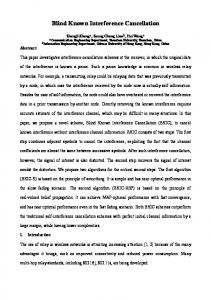
7. Performance Analysis of Parallel Channel Systems A parallel channel system means that we handle multiple data rates by allowing each user to transmit over more than one channel. In this way we can use the benefits of pure synchronous transmission. We then know that the received signals will be affected by the same channel parameters and we can also make use of codes with good cross-correlation properties [9]. In Figure 7 we show three different systems with the same throughput employing one- and two-stage IC. We have two asynchronous systems, one with 15 16-QAM users and one with 30 QPSK users. The third system contains 15 QPSK users where each user employs two parallel channels. The graph 0
10
Average Bit Error Probability
One way to handle multiple data rates is to let the users employ different modulation formats. We refer to this as a mixed modulation system. To compare the users we let the average SNR/ bit be equal for all the users independent of modulation format and the average BER is a weighted sum of the separate users BER using the rates as weights [9]. Figure 5 shows the results of one- and two-stage IC where the mixed system contains 20 BPSK, 10 QPSK and 5 16-QAM users all together. The code length is 127. The average BER of each kind of user is also shown. Figure 6 shows the result of twice as many users of each kind in another mixed system, i.e. 40 BPSK, 20 QPSK and 10 16-QAM users. In this case one-, two- and three-stage IC have been used. We gather from the graphs that by adding extra stages of IC in our receiver we will get a respectable decrease in BER (close to the single BPSK user bound) and a great increase in capacity. It should be emphasised that the system represented in Figure 5 includes 35 users and the system in
Processing Gain = 127 Random Sequences −1
10
IC 1 −2
10
IC 2 −3
10
Av. BPSK Av. QPSK Av. 16−QAM Mix (40/20/10) Single BPSK
IC 3
−4
10
0
5
10
15 20 Eb /N0 (dB)
25
30
35
Figure 6 Average BER for a mixed modulation system (70 users) with and without multi-stage IC under fading.
9. References
0
Average Bit Error Probability
10
[1] K. S. Gilhousen, I. M. Jacobs, R. Padovani, A.J. Viterbi, L.A. Weaver, and C. E.Wheatley III, “On the capacity of a cellular CDMA system,” IEEE Trans. on Vehicular Technology, vol. 40, pp.303-311, May. 1991.
Processing Gain = 127 Gold Sequences −1
Conv
10
[2] R. Lupas and S. Verdu, “Near-far resistance of multiuser detectors in asynchronous channels,” IEEE Trans. on Communications, vol. COM-38, pp. 497-507, April 1990.
−2
10
IC 1 −3
10
16−QAM (15) QPSK (15, P=2) QPSK (30) Single BPSK
[3] Z. Xie, R. T. Short and C. K. Rushforth, “A family of suboptimum detectors for coherent multiuser communications,” IEEE Journal on Sel. Areas in Com., vol. 8, pp 683-690, May 1990.
IC 2
−4
10
0
5
10
15 20 Eb /N0 (dB)
25
30
35
Figure 7 Average BER for a parallel channel system and asynchronous systems with and without multi-stage IC under fading.
shows that the parallel channel system and corresponding asynchronous system with QPSK users perform equally well in the case of a one-stage IC (the curves are almost not distinguishable). The gain in performance obtained from the use of parallel channels is lost because the next strongest user is equivalent to two interferers. Though when employing a twostage IC the parallel system decreases its BER considerably more than the asynchronous systems. This is obvious considering that in a multi-stage IC the interference is not directly connected to the powers of the other users and now the advantage of the synchronous channels gives the additional decrease in BER.
8. Conclusions We show that the one-stage IC scheme for M-ary rectangular QAM can easily be extended to a multi-stage IC scheme. The performance of different single modulation systems, with the same throughput, is compared with systems employing conventional detectors and the single user bounds. In the analysis we consider two methods for handling multiple data rates, mixed modulation and parallel channels. These methods are analysed under the assumption of Rayleigh fading. The conclusions are that a highly flexible system with very low BER is obtained using the multi-stage IC scheme together with parallel channels or mixed modulation. The greatest flexibility, though, is obtained by combining the two methods for handling multiple data rates. We also show that the number of users may be increased considerably, without increasing the BER, if the multi-stage IC scheme is used. Though, the restrictions are that the number of stages in the scheme is limited by the processor power and the largest acceptable delay.
[4] A. Duel-Hallen, “Decorrelating decision-feedback multiuser detector for synchronous code-division multiple access channel,” IEEE Trans. on Communications, vol. COM-41, pp. 285-290. Feb. 1993. [5] P. Patel and J. Holtzman, “Analysis of a DS/CDMA successive interference cancellation scheme using correlations,” Proceedings, Globecom (Houston, Texas), Dec. 1993. [6] P. Patel and J. Holtzman, “Analysis of a simple successive interference cancellation scheme in a DS/CDMA”, IEEE Journal on Sel. Areas in Com., vol. 12, pp. 796-807, June 1994. [7] Magnus Ewerbring, Björn Gudmundson, Gustav Larsson and Paul Teder, “CDMA with interference cancellation: A technique for high capacity wireless systems,” Proceedings ICC’93 (Geneva, Switzerland), May 1993. [8] A. Johansson and A. Svensson, “Successive interference cancellation in multiple data rate DS/CDMA systems”, Proceedings VTC’95 (Chicago, Illinois), July 1995. [9] A. Johansson and A. Svensson, “Successive interference cancellation schemes in multi-rate DS/CDMA systems,” Proceedings WINLAB Workshop (Rutgers University, New Jersey), April 1995. [10] M. Varanasi and B. Aazhang, “Multistage detection in asynchronous code-division multiple access communications,” IEEE Trans. on Communications, vol. COM-38, pp. 509-519, April 1990. [11] Z. Siveski, L. Zhong and Y. Bar-Ness, “Adaptive multiuser CDMA detector for asynchronous AWGN channels”, Proceedings, PIMRC ‘94 (The Hague, The Netherlands), Sept. 1994. [12] A. Kaul and B.D. Woerner, “Analytic limits on performance of adaptive multistage interference cancellation for CDMA”, Electronics Letters, vol. 30, pp 2093-2095, Dec. 1994. [13] Ying Li and R. Steel, “Serial interference cancellation method for CDMA”, Electronics Letters, vol. 30, pp 1581-1583, Sept. 1994. [14] J. G. Proakis, Digital Communications, 2nd ed, McGraw-Hill, 1989. [15] A. Papoulis, Probability, Random Variables, and Stochastic Processes, 3rd ed, McGraw-Hill, 1991.