Multi-Terrain Vertical Drop Tests of a Composite Fuselage Section Sotiris Kellas and Karen E. Jackson
[email protected],
[email protected] Structural Dynamics Branch NASA Langley Research Center, Hampton VA
ABSTRACT A 5-ft-diameter composite fuselage section was retrofitted with four identical blocks of deployable honeycomb energy absorber and crash tested on two different surfaces: soft soil, and water. The drop tests were conducted at the 70-ft. drop tower at the Landing and Impact Research (LandIR) Facility of NASA Langley. Water drop tests were performed into a 15ft-diameter pool of water that was approximately 42-in. deep. For the soft soil impact, a 15-ft-square container filled with fine-sifted, unpacked sand was located beneath the drop tower. All drop tests were vertical with a nominally flat attitude with respect to the impact surface. The measured impact velocities were 37.4, and 24.7-fps for soft soil and water, respectively. A fuselage section without energy absorbers was also drop tested onto water to provide a datum for comparison with the test, which included energy absorbers. In order to facilitate this type of comparison and to ensure fuselage survivability for the noenergy-absorber case, the velocity of the water impact tests was restricted to 25-fps nominal. While all tests described in this paper were limited to vertical impact velocities, the implications and design challenges of utilizing external energy absorbers during combined forward and vertical impact velocities are discussed. The design, testing and selection of a honeycomb cover, which was required in soft surface and water impacts to transmit the load into the honeycomb cell walls, is also presented. Introduction Helicopter designers face major challenges in establishing crashworthiness due to the multitude of possible impact orientations and the unknown morphology of the crash site, with surfaces such as concrete and water being at the extreme. For hard and non-yielding impact surfaces, the vehicle’s kinetic energy has to be managed by the airframe, and internal and/or external energy absorbing devices to ensure load attenuation and adequate post-crash cabin volume. Often, legacy airframes have little or no internal structure designed for crash energy management. Consequently, external energy absorbers with large stroke capability are often necessary. For hard surface impact the cross-section of the external energy absorber is not important as long as stroking is not hindered. Conversely, for water impact the energy absorber stroke is less relevant since peak dynamic loads are brief and typically last only as long as it takes for the vehicle to break through the water surface. However, the shape of the penetrating surface is much more critical and typically determines the magnitude of the peak load. For example, devices such as landing gear and/or skids, which can be very effective in absorbing energy on relatively hard surfaces, are rendered useless during water impacts. Moreover, protruding
_______________________________ Presented at the American Helicopter Society 64th Annual Forum, Montréal, Canada, April 29 - May 1, 2008.
devices used for energy absorption can become a liability during water, or soft soil, impacts that involve large forward velocities, since they cause the aircraft to be more sensitive to tumbling. In addition to conventional retractable landing gear other externally deployable devices, which have been proposed, for helicopter active crash protection include vented airbags [1], porous airbags, [2], and a deployable honeycomb concept [3, 4]. Since landing gears and/or skids are ineffective during water impact, Michielsen et al [5] have proposed the tensor skin panel concept where crash energy is dissipated by the deflection of an energy absorbing composite sandwich belly panel. In essence, this is a similar approach to the one previously proposed by Kellas [6] where most of the crash energy is dissipated by crushable structure placed between a rigid floor and a flexible aerodynamic cowling and, therefore, for both concepts, stroking is limited by the available subfloor space. The multi-terrain capability of the concept, proposed by Kellas [6], was investigated by Sareen et al [7] for hard and soft surface impacts, and Fasanella et al [8] for water impact. While concepts with integrated subfloor energy absorption capability can help mitigate impact loads, their performance is limited by the crush stroke capacity – an area in which externally deployable energy absorbers have a clear advantage. The deployable energy absorber concept consists of a honeycomb structure [3, 4], which can be deployed externally to provide energy attenuation, much like an external airbag system. However, unlike airbag systems,
which are typically constrained to a spherical and/or cylindrical shape, the deployable honeycomb can be fabricated to have any shape. This advantage, coupled with superior shear stability as compared to airbags, make the concept a good candidate for multi-terrain impact applications. A study of the concept for helicopter crashworthiness was initiated under the NASA Subsonic Rotary Wing (SRW) Aeronautics Program. The Rotorcraft Crashworthiness part of the program has focused attention on two main areas of research: developing the externally deployable energyabsorbing concept for helicopter applications and improving analytical tools for predicting rotorcraft crashworthiness [9]. Preliminary results from the deployable honeycomb study were presented at the 2007 AHS Forum [10]. These included investigations into the dynamic crush performance of different honeycomb constructions and geometries. Results from a dynamic simulation of a 38.4-fps vertical drop test on concrete of a 5-ft-diameter composite fuselage section fitted with four deployable honeycomb energy absorbers were also presented. This paper presents additional full-scale vertical drop tests, involving the 5-ft-diameter composite fuselage section, where the impact surfaces were soft soil (sifted sand), and water. For each test the fuselage section was retrofitted with four identical blocks of the deployable honeycomb. The impact velocities were 37.4 and 24.7-fps for soft soil and water, respectively. For these tests, the surface of the honeycomb energy absorbers was covered to enable crushing. A fuselage section without energy absorbers was also drop tested onto water to provide a datum for comparison with the test with energy absorbers. In order to facilitate this type of comparison and to ensure fuselage survivability for the no-energy-absorber case, the velocity of the water impact tests was restricted to a nominal of 25-fps. Experimental results A necessary requirement for the successful utilization of the deployable honeycomb in multi-terrain impact applications is the capability to transfer load from the impact surface into the cell walls to initiate progressive crushing. Essentially, for soft surface impacts, the honeycomb must be prevented from acting as a “cookie cutter”. Therefore, the honeycomb’s surface, which contacts the impact surface, must be covered. While the primary role of a cover is to introduce the load into the honeycomb cells, the cover also has to be geometrically compatible with the energy absorber – both in its stored and deployed stages. Several energy absorber cover concepts were considered and the ones that met all design requirements for vertical impacts were fabricated and tested prior to full-scale impact testing. Friction, which is an important parameter in forward impact velocities, was not considered in this preliminary cover design study. A typical
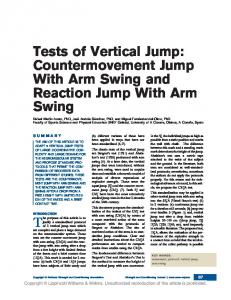
geometry of a covered schematically in Figure 1.
energy
absorber
is
shown
Deployment Direction
Stroking Direction
R Cover Curvature Depth R=Radius of Curvature Impact Surface: Cylindrical Nose Fig. 1 Schematic of a covered deployed energy absorber with a cylindrical impact nose. Preliminary Water Impact Tests The energy absorber cover development was guided primarily by water impact, which is thought to be the most demanding condition. Therefore, a series of water impact tests was conducted using deployable honeycombs fitted with covers. The deployable honeycombs were of the same construction as those used on the previous full-scale fuselage drop test on concrete [10]. In addition to cover concepts, the effect of the energy absorber’s nose shape was also investigated during this preliminary water impact study. Examples of three cover concepts are shown in Figure 2. All tests of this type were conducted using a 12-ft drop tower, which was equipped with a water tank at its base as shown in Figure 3. The video frames of Figure 3 show the droptower guide rails, the water tank, the energy absorber secured on the underside of the cross-head, and two sliding stops used to arrest the cross-head after water impact. Due to the relatively small volume of water used in these tests, the cross-sectional area of each energy absorber sample was kept uniform for all tests to allow for a meaningful comparison.
2(a) Rigid cover with flexible hinges. Cover consists of four overlapping pieces.
2(c) Flexible cover over a doubly curved surface. Cover consists of four overlapping pieces. Fig. 2 Deployable honeycomb cover concepts. Honeycombs are shown in semi-deployed stage. When fully deployed the impact nose of the honeycombs (a) and (b) is cylindrical as compared to spherical for (c). Typical results from the preliminary water impact tests are shown in Figure 4. The study verified that the nose shape of the energy absorber is very important with the relatively sharp spherical-nose case generating insufficient reaction load to initiate crushing. Moreover, in the case of the more blunt 0.75-in. cylindrical-nose, the pulse was so short in duration that very little (less than an inch) crushing was observed. In summary, when the energy absorber nose was sharp the peak load attenuation was the greatest but the dissipation of kinetic energy was the least. When the nose of the energy absorber was shaped to attenuate the initial peak load down to the energy absorber’s sustained crush load, less than an inch of crush was observed.
2(b) Rigid cover with flexible hinges. Seven pieces were used, one over each row of cells.
The study also showed that, at least for the vertical impact cases, the type of cover was much less important than the shape of the honeycomb’s nose. Based on the preliminary water impact tests the cover shown in Figure 2(a) was chosen for use in subsequent full-scale tests on water and soft-soil (sand). This cover was selected with the assumption that it would provide the best performance in more complex impact scenarios involving combined vertical and forward velocity conditions.
The 5-ft-diameter composite fuselage section, which was used previously for hard surface impact [10], was also used for water and soft-soil impact. The total fuselage weight (including the weight of ten 100-lb lead blocks) was 1,212lb. Lead blocks were secured onto the fuselage floor through standard seat rail fasteners. The honeycomb cell walls were made of a single woven-ply of Kevlar-129, had a cell width equal to 1.0-in., and weighed 5.6 lb each. The deployed size of the honeycomb was 20-in. tall, 16.5-in. wide and 20.5-in. deep and each block was fitted with a cover, which added 0.25-lb. to the total weight of each energy absorber. A schematic of the energy absorber is shown in Figure 1. With the exception of the covers, the energy absorbers were otherwise identical to the ones used on hard surface impact [10], including their cylindrical shaped nose with 18-in. radius of curvature. The honeycombs were sized based on the original hard-surface impact case, [10], with the assumption that the crash energy of a 40-fps impact would be managed through crushing of the energy absorber while restricting the dynamic loads to less than 20-g. Therefore, 20-g was the target level for the sustained crushing load, also referred to as the energy absorber design crush load. The 18in cylindrical curvature was necessary to attenuate the initial peak loads for hard surface impacts but was not optimum for the soft and water surface impacts. Nevertheless, this curvature was maintained for consistency between tests.
Fig. 3 Progressive video frames from a typical water impact test using the 12-ft. drop tower.
Full-Scale Soft-Soil Impact Test Full-scale drop tests on soft-soil were conducted using the 70-ft. drop tower at the Landing and Impact Research (LandIR) Facility of NASA Langley. For this test, a 15-ftsquare container filled with fine-sifted, unpacked sand was placed at the base of the drop tower as shown in Figure 5.
14000
Penetration Resistance, lb
As in the case of the hard surface impact test, the fuselage was dropped onto the impact surface from a height of approximately 26-ft. The attitude of the fuselage was constrained by the portal system so that the floor remained horizontal and the velocity at impact was measured to be 37.4-fps. Following the full-scale test, the fuselage was carefully removed from the impact area to allow for soil characterization tests to be performed around the impact area.
0.75" Deep Cyl. Curvat. @ 23.5 fps 3.0" Deep Spher. Curvat. @ 24.5 fps Flat and Rigid Surface @ 24.5 fps
12000
10000
8000
6000
Aver. Sustained Crush Level
4000
2000
0
0
0.5
1
1.5
2
2.5
3
3.5
4
Water Penetration, inches
Fig. 4 Nose-shape effect on water impact loads. The average sustained crush level was verified in previous impact tests of similarly constructed honeycombs on a hard surface.
Post-test inspection revealed that the kinetic energy of the fuselage was only partially absorbed by honeycomb crushing and a large portion was, therefore, dissipated through soil penetration. Though no supporting evidence is offered, it is highly probable that soil penetration occurred first. As the soil became compacted and resistance increased, energy began to be dissipated through energy absorber crushing. Following the drop hammer tests, the energy absorbers were carefully removed from the impact surface and penetration measurements were taken at each energy absorber location.
The maximum penetrations for the two front and rear locations were approximately 7.5-in. and 9.0-in. respectively.
Fig. 6 Drop-hammer impact locations. Tests were conducted immediately after the fuselage drop test to ensure unchanged moisture content. Post-test inspection of crushed energy absorbers revealed that the majority of the crushing occurred at the impact surface (covered honeycomb face). Some honeycomb crushing also occurred at the fuselage interface as the photograph of a partially crushed energy absorber shows in Figure 7.
Fig. 5 Fuselage section fitted with four energy absorbers (deployable honeycombs) shown suspended approximately 26-ft above the soft impact surface prior to test. Drop hammer (penetrometer) tests were conducted from a drop height of approximately 48-in. soon after the fuselage drop test to ensure unaltered soil conditions (moisture content). The intention of the tests was twofold: to provide an indication of soil uniformity across the impact surface, and to provide soil characterization in the form of acceleration-time responses to facilitate future analytical simulations of the impact surface. The 20-lb. drop hammer had a hemispherical impact surface (Diameter = 10-in.) and was instrumented with a triaxial accelerometer pack. A total of five points around the impact area were surveyed using the drop hammer, as shown in Figure 6. Maximum penetration depth and acceleration-time histories from the five impacts indicated some variability within the impact area thought to be associated with the fact that the soil was not packed. Measured penetrations were in the range of 3.5 to 5.0-in deep and the average was 4.45-in.
Fig. 7 Post-test photograph of the front left energy absorber. The energy absorber is shown up side down with respect to the test orientation. A comparison of the acceleration-time response between the 37.4-fps impact on soft-soil and the 38.4-fps impact on concrete [10] is shown in Figure 8. Despite the differences in the mode of energy dissipation, the two responses appear to
be very similar in shape, with the peak load magnitude being approximately 2 to 3-g lower for the soft-soil impact. 30 Concrete, Vo = 38.4 fps Sifted Sand, Vo = 37.4 fps
Acceleration, g
25 20 15 10 5 0 0
20
40 60 Time, ms
80
100
Fig. 8 Acceleration-time responses for concrete and soft-soil surface impact. The concrete surface impact data are from reference [10]. Full-Scale Water Impact Tests Two full-scale drop tests were conducted on water. The fuselage section without energy absorbers was tested first to provide a datum for comparison with the second test, which included four deployable honeycomb energy absorbers. In order to facilitate this type of comparison and to ensure fuselage survivability for the no-energy-absorber case, the velocity of the water impact tests was restricted to a nominal of 25-fps. The two test configurations are shown prior to impact in Figure 9. The measured velocities at impact were 24.7 and 25.0-fps for the test with and without energy absorbers, respectively.
(a) Fuselage-section without energy absorbers.
For these tests a 15-ft-diameter pool of water (approximately 42-in. deep) was placed at the base of the 70-ft drop tower. The pool was fitted with a clear window to allow for highspeed video of the impact with the water. Under water highspeed video, as well as post-test inspection of the energy absorbers, revealed that very little honeycomb crushing occurred. A comparison of the acceleration-time responses from the two water impact tests is shown in Figure 10. A significant attenuation of initial peak load is apparent for the test with the energy absorbers. However, high-speed video and posttest investigation revealed that practically all of the attenuation was achieved by the reduced cross-section contacting the water rather than from honeycomb crushing. The acceleration-time response of Figure 10 also confirms that the honeycomb’s design-crush-load of 20-g was not quite reached.
(b) Fuselage-section with externally deployable energy absorbers fitted. Fig.9 High-speed video frames prior to impact on water.
160 Without Energy Abs., Vo = 25.0 fps With Energy Abs., Vo = 24.7 fps
Acceleration, g
120
80
40 Crush Design Level 0
0
10
20
30
40
50
Time, ms
Fig. 10 Acceleration-time responses measured at the fuselage floor after a 25-fps, nominal, vertical drop on water. Discussion A summary of results from full-scale impact tests on hard, soft, and water surfaces of the fuselage section fitted with the deployable honeycomb are presented in Figure 11. Acceleration-time responses confirm the ability of the externally deployable concept to attenuate the vertical average accelerations to, or below, the honeycomb’s design crush-load. 30 Concrete, Vo = 38.4 fps Sifted Sand, Vo = 37.4 fps Water, Vo = 24.7 fps
Acceleration, g
25 20 15
volume. Though effective in attenuating the initial peak, the energy absorbers were not able to absorb kinetic energy through crushing. This finding is by no means a drawback of the energy absorber but simply a reality associated with water impact. The initial peak-load, which occurs during the penetration of the water surface, is too brief to promote sustained crushing. Once the energy absorbers break through the water surface there is simply not enough resistance to maintain crushing. This claim is supported by the preliminary water impact tests where various nose curvatures were tested. As shown in Figure 4, the honeycomb with 0.75-in. deep cylindrical nose had just the right amount of curvature to attenuate the initial peak load, and initiate crushing. However, the amount of crushing was limited to less than one inch. A similar fuselage section with an integrated crushable foam subfloor concept and simulated payload was used in previous studies involving vertical drop tests on various impact surfaces [7, 8]. Sareen et al [7] studied the response of the fuselage section during a 25-fps vertical drop on a hard surface and soft soil (sand) and Fasanella et al [8] reported on the response of the same fuselage section during a 25-fps vertical drop on water. Therefore, a loose comparison of the two concepts can be made for corresponding impact surfaces. For impact on hard surface (concrete) the deployable honeycomb has a clear advantage over the integrated crushable foam concept. Despite the fact that the kinetic energy at impact for the fuselage with the deployable honeycomb was 2.36 times greater than that of the fuselage with integrated crushable foam, the dynamic loads were attenuated to an average of less than 20-g for the deployable honeycomb as compared to 25-g for the more conventional concept. This advantage is attributed directly to the fact that the externally deployable honeycomb had a greater crush stoke available than the integrated crushable foam.
10 5 0 0
20
40 60 Time, ms
80
100
Fig. 11 Acceleration-time responses for hard, soft-soil, and water surface impact. Hard surface impact data are from reference [10]. Load attenuation through crushing occurred in both hard and soft-soil impact surfaces. In those cases the impact surface provided adequate reaction load to initiate and maintain stable crushing. However, for water impact, energy was dissipated primarily by accelerating the displaced water
In the case of the soft soil impact, the deployable honeycomb also exhibited a superior performance over the integrated crushable foam concept. Despite the fact that the kinetic energy at impact for the fuselage with the deployable honeycomb was 2.24 times greater than that of the fuselage with integrated crushable foam, the peak dynamic loads were attenuated to less than 27-g as compared to 31-g. In this case, the honeycomb dissipated energy by both penetration and crushing and maintained a relatively flat response. To the contrary, the kinetic energy of the fuselage with the integrated foam concept was dissipated primarily by soil penetration. For water impact, stroke availability is less important and the most critical factor is the shape of the impacting object. Consequently, no significant amount of energy was dissipated by honeycomb crushing. Instead most of the
kinetic energy was absorbed through the acceleration of the displaced water. With the exception of the initial peak, which was lower for the deployable honeycomb, the two concepts had a comparable response with respect to dynamic load magnitude with loads being attenuated to approximately 19-g. These results demonstrate that even for the simple case of vertical impact, designing for multi-terrain capability can be extremely complex due to the different, and often opposing, requirements for each impact surface. For example, the cylindrical-shaped nose of the deployable honeycomb was necessary for hard surface impacts in order to attenuate the initial peak [10]. However, for water impact the cylindrical nose promoted faster water-surface penetration (less water resistance) and hence less energy dissipation by crushing. Moreover, it is postulated that the large energy absorber stroke needed for hard surface impacts can become a liability in the case of water, or even soft-soil, impacts involving combined vertical and forward velocity conditions. Therefore, designing for multi-terrain impact applications could either result in a significant penalty in energy absorber mass, or reduced energy absorbing capability across multiple terrains. An advantage that the deployable honeycomb has over other deployable systems is that its shape is not constrained. This freedom along with options of partial honeycomb deployment to limit protrusions during water impact is the subject of future work. In addition, the deployable honeycomb will be sized and shaped for multi-terrain impact applications with combined forward and vertical components of velocity. Conclusions Preliminary water impact studies into the relationship of energy absorber shape and kinetic energy absorbed revealed that the shape of the energy absorber is the most important factor and, at best, only a very small amount of energy can be dissipated through energy absorber stroking or crushing. Typically, the reaction load necessary to initiate and maintain sustained crushing is far too brief and lasts only as long as it takes for the energy absorber to break through the water surface. Results from fuselage vertical drop impacts on soft-soil and water surfaces showed that the deployable honeycomb concept can be an effective dynamic load attenuator. Both test cases required the honeycomb energy absorbers to be covered. The chosen cover was made of Kevlar with flexible hinges to facilitate honeycomb packaging and deployment. In the case of fuselage drop tests on soft-soil, dynamic load was attenuated and maintained at, or below, the desired load level through a combination of soil penetration and honeycomb crushing. For the fuselage drop on water a comparison of cases with and without external energy
absorbers showed that the energy absorbers were effective in attenuating the initial peak loads by displacing the water surface. However, no significant crushing took place. Acknowledgment This work is funded under the NASA Subsonic Rotary Wing (SRW) Aeronautics Program. Reference
[1] Bolukbasi A. O. “Active Crash Protection Systems for [2]
[3]
[4]
[5]
[6]
[7]
[8]
[9]
UAVs,” Proceedings of the 63rd AHS Annual Forum, Virginia Beach, VA, May 1-3, 2007. Yosef V., BenMoshe A, Noyman Y., Gansman B., and Bradney C., “Rotorcraft External Airbag Protection System,” Proceedings of the AHS 62nd Annual Forum, Phoenix AZ, May 2006. Kellas S., “Deployable Rigid System for Crash Energy Management,” US Patents 6,755,453, June 29, 2004, 6,976,729 December 20, 2005 and 7,040,658 May 9, 2006. Kellas S., “Externally Deployable System for Crash Energy Management,” Proceedings of the National Technical Specialists’ Meeting on Rotorcraft Structures and Survivability, Williamsburg VA, Oct. 25-27, 2005 Michielsen A. L. P. J., Wiggenraad J. F. M., Ubels L. C, Frijns R. H. W. M., Kohlgueber D., Labeas G., and McCarthy M. A., “Design, Test and Analysis of Tensor Skin Panels for Improved Crashworthiness in Case of Water Impact,” AHS/SAFE Crashworthiness Specialists’ Meeting on Crash Safety Challenges and Innovative Solutions, Phoenix, AZ, 14-16 September 1998. Kellas S., "An Experimental Investigation into the Energy Absorption Performance of Composite Beam Webs For Aircraft Subfloor Applications," AHS National Technical Specialists' Meeting on Rotorcraft Structures, "Design Challenges and Innovative Solutions," Williamsburg, VA, Oct. 1995. Sareen A. K., Fasanella E. L., Sparks C. E., Jackson K. E., and Mullins B. R. Jr., “Comparison of Hard Surface and Soft Soil Impact Performance of a Crashworthy Composite Fuselage Concept,” Proceedings of the 58th AHS Annual Forum, Montreal, Canada, June 11-13, 2002. Fasanella, Edwin L., Jackson, Karen E., Sparks, Chad E., and Sareen, Ashish K., “Water Impact Test and Simulation of a Composite Energy Absorbing Fuselage Section,” Journal of the American Helicopter Society, Vol. 50, No. 2, April 2005, pp. 150-164. Jackson, K. E., Fuchs, Y. T., and Kellas, S., “Overview of the NASA Subsonic Rotary Wing Aeronautics Research Program in Rotorcraft Crashworthiness,” Proceedings of the 11thASCE Earth and Space
Conference, Special Symposium on Ballistic Impact and Crashworthiness of Aerospace Structures, Long Beach, CA, March 3-5, 2008.
[10] Kellas S. and Jackson, K. E., “Deployable System for Crash-Load Attenuation,” Proceedings of the 63rd AHS Annual Forum, Virginia Beach, VA, May 1-3, 2007.