Index Terms-MIMO, OFDMA, FFR, Interference, Cellular. 1. INTRODUCTION. Multi-user MIMO for the downlink of next-generation mobile broadband access is ...
MULTI-USER MIMO AND ADAPTIVE FREQUENCY REUSE FOR NEXT-GENERATION MOBILE BROADBAND NETWORKS Clark Chen*, Yang-seok Choi**, Nageen Himayat*, Minnie Ho*, Vladimir Kravtsov**, Guangjie Li*, Qinghua Li*, Yuval Lomnitz**, Hongmei Sun*, Hua Yang*, Shilpa Talwar*, Hujun Yin**, Hongming Zheng*, Shanshan Zheng* *
Corporate Technology Group, Intel Corporation, **Mobile Wireless Group, Intel Corporation ABSTRACT
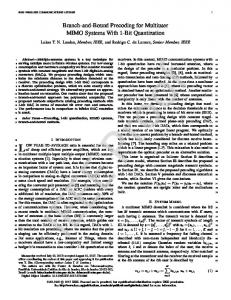
In order to meet the constantly increasing demand for ubiquitous, mobile access to the internet, next-generation mobile broadband communications systems based on OFDMA, such as IEEE 802.16m, require a significant performance increase over previous generation systems, such as IEEE 802.16e-2005, particularly in cell-edge and average spectral efficiency [2]. In this paper, we address the downlink adaptive frequency reuse (AFR) and multi-user MIMO (MU-MIMO) techniques which are considered to be the most promising candidates for meeting the requirements on cell-edge and average spectral efficiency of next-generation mobile broadband systems. Index Terms-MIMO, OFDMA, FFR, Interference, Cellular 1. INTRODUCTION Multi-user MIMO for the downlink of next-generation mobile broadband access is the technique where multiple users are simultaneously scheduled on the same resource block, and data streams are simultaneously transmitted by the base station (BS) to each of the multiple mobile stations (MSs) using spatially-distinct “beams”. MU-MIMO has drawn more attention in the recent years because of the benefits that can be obtained from both multi-user and spatial diversity and the possibility for implementation in real-world mobile broadband networks due to advances in wireless communications electronics expected for nextgeneration OFDMA-based wireless systems. In order to facilitate network management and to increase spectral efficiency, a tight frequency reuse factor is preferred by network operators. In such scenarios, inter-cell interference becomes a major issue. In OFDMA systems, if two users in neighbor cells are assigned the same frequency, the co-channel frequency interference between neighbor cells can be very severe. Figure 1 shows a contour plot of the downlink average SINR (signal-andinterference-to-noise ratio) measured at the MS receiver in a reuse 1 network. Each hexagonal cell consists of 3 sectors, each with a 120-degree directional antenna. The SINR decreases as the MS is situated further away from the
978-1-4244-2354-5/09/$25.00 ©2009 IEEE
3617
serving BS sector, which is represented by the color changing from red to blue. At the cell boundaries, the SINR is around 0 dB or even lower. SINR below 0 dB makes it difficult to support fast and robust transmissions for users typically located at the cell-edge. Such users will likely experience a poor network connection, low downlink throughput, and high probability of outage. Thus, interference becomes the biggest barrier for cell-edge user performance. There are various ways of combating co-channel interference, such as transmitter interference randomization, transmit beamforming, receiver interference cancellation, power control, and fractional frequency reuse. Next generation standards striving for universal frequency reuse to maximize spectrum utilization and efficiency will support one or more of these techniques for active interference management. In addition to MU-MIMO techniques, this paper provides a detailed description on how Adaptive Frequency Reuse (AFR) [3] can be used to improve downlink cell-edge performance while retaining the system spectral efficiency of the system with frequency reuse factor equal to one. 2. MULTI-USER MIMO (MU-MIMO) The received signal at the i-th MS (without considering co-channel interference) is described by K
y i , f = H i , f ∑ v j , f x j , f + ni , f ,
(1)
j =1
where K is the number of the allocated users in subcarrier f, Hi,f is the channel matrix of the f-th subcarrier at the i-th MS, vj,f is the precoding vector of the f-th subcarrier for the transmit signal to the j-th MS, xj,f is the transmit signal to the j-th MS, and ni,f is the additive noise at the i-th MS. In unitary MU-MIMO, the columns of the assembled V j , f = [v1, f , v 2, f ,..., v K , f ] are precoding matrix orthogonal to each other, while they are not orthogonal for the case of non-unitary MU-MIMO, see Sections 2.1 and 2.2 for a description of the considered unitary and nonunitary MIMO techniques, respectively.
ICASSP 2009
is paired with the first user to maximize the overall predicted throughput. The precoding matrix can then be computed using a zero-forcing algorithm as follows:
Wi , j = cC (v ) H (C (v )C (v ) H ) −1 ; C (v ) = [vi , v j ] H (3) where c is a normalization factor. At the MS, the CQI calculation is updated using the precoding matrix as follows:
[CQI i' , CQI 'j ] = [CQI i , CQI j ] ⋅ diag (C (v) ⋅ Wi , j ) (4) The throughput is recomputed at the BS with the updated CQI information until all users are paired according to the following formula
Figure 1: Contour figure of SINR in reuse 1 networks 2.1. Unitary MU-MIMO We focus on a particular form of unitary MU-MIMO that is based on a codebook search for predefined weights. This is basically an extension of single-user open-loop (SU OL) random beamforming concepts to MU-MIMO. According to the considered technique, the precoding matrix V, see (1), is predefined and stored at both the BS and MS. Semi-static changing of the V matrix is possible according to information on the MS statistics. Both pilot and data subcarriers are precoded by the same predefined precoder. The CQI (channel quality indicator) estimation is based on the SINR calculation from the precoded pilots (effective channel). The MS reports the CQI of the preferred spatial stream among all streams to the BS. Based on the CQI received from the MSs, the BS performs user scheduling and selects the paired users using the maximum of the sum rate for data transmission with the constraint of fairness. By this method, CSI (channel state information) feedback is not required, which significantly reduces the control overhead. When the number of users is large, the performance is shown to approach that of MUMIMO techniques where CSI feedback is utilized.
Throughput{i, j} = (det(I + H i , j H i , j ) , H
H i , j = diag (sqrt ([CQI i' , CQI 'j ])) ⋅ C (v ) ⋅ Wi , j
(5) (6)
Modulation and coding rates for each of the users are chosen using the updated CQI information. The codebook is chosen through Householder transformations such as in the IEEE 802.16e-2005 standard or through the columns of a DFT matrix. We have found that a transformation of the IEEE 802.16e-2005 codebook using the channel correlation matrix gives a codebook that offers stable performance for correlated as well as uncorrelated channels [1]. For predefined MU-MIMO, see Section 2.1, no CSI is needed for feedback. For the MU ZF scheme of this section and for two transmit antennas at the BS, 3.03 bits/user/subband/5ms are required per transmission. This is similar to the number of feedback bits required for closed-loop (CL) SU MIMO. For four transmit antennas at the BS, 3.12 bits/user/sub-band/5ms are required, which is much less than the number of feedback bits required for CL SUMIMO. 3. ADAPTIVE FREQUENCY REUSE
2.2. Non-unitary MU-MIMO In this paper, we focus on a particular form of nonunitary MU-MIMO that is based on a codebook search and a zero-forcing algorithm at the BS for forming the beams. According to the considered technique, the MS feeds back both quantized CSI and an indication of the CQI. The CSI is computed by performing singular value decomposition (SVD) of the channel matrix H, see (1), and selecting a codeword from a codebook C that is closest to the maximal right singular vector in terms of the inner product. The CQI is based on the SINR calculation and is computed using an assumed precoding matrix formed with the maximal right singular vector, v, and the null-space of v:
P = [v, null (v )]H
(2) At the BS, pairing of users is an iterative process. The first user with maximal CQI is selected, and a second user
3618
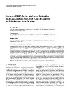
Higher frequency reuse factors, such as 3, can significantly reduce the co-channel interference amongst neighboring cells/sectors. This leads to greatly improved coverage and average SINR for cell-edge users. Similarly, reuse 3/2 can also reduce the co-channel interference by allowing the same frequency to be reused by 2 of every 3 neighboring cells/sectors. It results in much better average SINR distribution compared to reuse 1, as can be seen from Figure 2. However, improvement of the downlink average SINR by using higher reuse factors is achieved at the cost of system spectrum efficiency, since higher reuse also requires more spectrum bandwidth. To achieve better coverage, while still retaining the high system spectrum efficiency of reuse 1, a mixed reuse architecture is proposed which enables multiple reuse factors in the same network. This architecture referred to as “Adaptive Fractional Frequency Reuse (AFR)” requires
multi-function cross-layer design encompassing PHY, MAC, and Network layers. The term adaptive refers to the ability to adapt to time-varying traffic conditions and user distributions. The key elements of the AFR architecture include reuse partitioning, interference-aware scheduling, and interference-aware BS coordination. Empirical CDF 1 Reuse1 Reuse3/2 Reuse3
0.9 0.8
partitions can be unused or have lower/higher transmission power. A system cost (weight) is associated with each partition which reflects the measure of the overall system resource used by the partition, such as effective bandwidth due to reuse, transmission power, and interference to other cells. As an example, the cost of a partition is high if this partition is restricted in other sectors to create higher reuse pattern (3, 3/2), or if the partition uses higher transmission power and causes interference to neighbor cells.
0.7
F(x)
0.6 0.5 0.4 0.3 0.2 0.1 0 -10
Figure 3 Framework of AFR 0
10
20 30 Geometry SINR (dB)
40
50
60
Figure 2 Average SINR CDF of uniformly distributed MS in networks with different reuse factors 3.1. Reuse Partitioning To implement AFR, the OFDMA symbol bandwidth is split into 4 to 7 frequency sub-bands, 3 of which support reuse 3, 3 sub-bands support reuse 3/2, and 1 sub-band supports reuse 1. The process of bandwidth splitting is denoted as “reuse partitioning,” and each frequency subband is called one partition group. Figure 3 illustrates the AFR partition for a network with 3 sectors per cell, marked by different colors. Such a network can support up to 3 reuse factors, which are reuse 1, reuse 3/2 and reuse 3. The frequency reuse pattern is created by restricting usage of certain frequencies or power level of these frequencies in a sector to minimize interference. These restrictions may change over time as a function of BS coordination to adapt to time-varying conditions. Under this AFR architecture both “soft reuse” and “hard reuse” can be supported. “Soft reuse” refers to the case where higher reuse factors are supported by restricting the interfering BS downlink transmit power on certain subcarriers rather than turning them off. On the contrary, “hard reuse” refers to the case where a higher reuse factor is achieved by shutting off the interfering BS on certain subcarriers. For all reuse schemes, the total downlink transmission power is kept constant and below the maximum allowed value. Soft reuse intuitively has capacity advantages when the system load is high because physically there is no bandwidth loss caused by frequency planning, while hard reuse is easier to deploy when system load is light. The presented AFR scheme results in usage of frequency partitions at each BS such that parts of frequency
3619
Cost of each partition is adjusted dynamically at each BS to adapt to time-varying MS traffic loads and distributions. The adaptation procedure starts with an initial cost value for each partition, which is iteratively increased/decreased by the BS based on number of bandwidth requests from MSs for the corresponding channel partitions. Hence, a partition in strong demand by MSs may incur a higher cost, while a partition that is largely unused may have a lower cost. The BS signals cost information to the MSs it serves, enabling the MSs to choose the best partition based on the measured SINR as well as the cost per partition. This procedure to adapt cost in a dynamic system is referred as “Market Price Iteration Algorithm”. It can be shown that cost will always converge to a unique and optimal value for a given MS distribution and propagation environment. 3.2. Interference-aware Scheduling The scheduler at BS allocates resources to an MS based on its preferred reuse partition and the SINR metrics reported by the MS. To determine the best partition, the MS measures its SINR on all reuse partitions, and estimates its spectral efficiency (SE) on the different reuse partitions. Then, the MS calculates its normalized SE (nSE) on different reuse partition/resource units as nSE reuse (i ) = SE reuse (i ) / Cost reuse (i ) (7) and picks the partition that maximizes the nSE. This process takes cost of resources into consideration, and enables system-wide optimization of resource utilization. Since the MS determines the best partition/resource, this method is associated with low feedback overhead. The MS only needs to feedback SINR information for resource units in its preferred partition.
In order to adapt to dynamic user distributions or system loads, an RRM (radio resource management) unit coordinates the AFR configuration amongst BSs in the cellular network. The following information may be reported to the RRM unit: Bandwidth partition, power level of each partition, cost of each partition, and bandwidth request/load on different FFR partitions. The RRM unit will determine a new FFR partition based on this information which minimizes system-wide interference. The new FFR partition and power settings are signaled to all neighboring BS. 4. SIMULATION RESULTS
distributed allocations, there is plenty of room to gain from AFR. RU is 64x6 with dynamic interference considered 10 SUCL MUZF Predefined MU
9 8 Gros s S E (bps/Hz/Cell)
3.3. BS Co-ordination
7 6 5 4 3 2 1 0
Tx2 Uncorrelated Tx2 4L 3d
4.1. MU-MIMO System-level simulation (SLS) results for MU-MIMO performance are provided for comparison. The simulation assumptions can be found in [5]. In the SLS, changing of the pre-coding matrix in neighboring cells will lead to fluctuations of the co-channel interference, known as dynamic interference. Dynamic interference will impact the accuracy of CQI estimation and will also have impact on the MU ZF performance, see Section 2.2, while predefined MU MIMO of Section 2.1 will not be impacted. In Figure 4, we test several channel conditions, from no correlation, low correlation (antennas at the BS are spaced 4λ apart, with 3 degrees of angular spread), and high correlation (antennas at the BS are spaced 0.5 λ apart, with 3 degrees of angular spread. We can see from the simulations that for channels with little or no correlation, the gain of MU-MIMO over CL SU-MIMO is about 8% in the low and uncorrelated cases for predefined MU-MIMO over CL SU-MIMO. For the case with high correlation (low cross-beam interference), the gain of MU-MIMO over CL SU-MIMO is much larger – about 25% gain. The increase is more pronounced with a higher number of antennas at the BS because of the higher beam-forming gain: About 28% gain with higher correlation, with 8% and 3% gain in the low and uncorrelated cases, respectively. 4.2. AFR System level simulations of both soft reuse and hard reuse AFR are conducted with assumptions fully compliant with [5]. The system is assumed to be 100% loaded with full buffer data traffic model. Channel estimation is ideal with CQIs on all resource units available at the BS. The results in Table 1 show that AFR-S has marginal gains on localized permutations but significant gain on distributed allocations. The reason is that PF scheduling with the localized permutation mode has already exploited the frequency selective scheduling gain, and AFR can not improve much without loss in cell-capacity. However, with
Tx2 0.5L 3d Tx4 Uncorrelated Tx4 4L 3d Different scenarios
Tx4 0.5L 3d
Figure 4: MU-MIMO performance comparison in different scenarios Scheme
Channel Model
SE (in bps/Hz/ Cell)
Localized baseline Localized AFR-S Distributed baseline Distributed AFR-S
ITU PedB3kmph
5.84
ITU PedB3kmph
3.68
5.93
4.52
Gain in SE
Cell-edge throughput (in Kbps)
Gain in celledge throughput
667 1.6%
689k
3.3%
315k 22.8%
595k
88.9%
Table 1: Results for AFR 5. CONCLUSIONS Based on the MU-MIMO simulation results, the gain over SU-MIMO can very significant, as much as 25% under highly correlated channel conditions. In order to increase the average spectral efficiency for next-generation mobile broadband systems, techniques utilizing both multi-user and spatial diversity such as MU-MIMO are considered to be indispensable. Based on the presented novel framework for AFR, the simulation results indicate that gains in both cell- edge user throughput and average SE are possible. The gain for distributed (802.16e-2005 PUSC-like) permutations is nearly 90% in cell-edge user throughput and 22% in SE. REFERENCES [1] Li, Qinghua, Li, Guangjie, Lin, Eddie, and Zheng, Shanshan, A Low Feedback Scheme for WMAN MIMO Beamforming, Radio and Wireless Symposium, Pages 349-352, Jan 2007. [2] C. Chen et al, Adaptive Frequency Reuse in IEEE 802.16m, IEEE Broadband Wireless Access Working Group, July 2008. [3] IEEE 802.16m Evaluation Methodology Document (EMD), July 2008, http://ieee802.org/16/tgm/docs/80216m-08_004r2.pdf
3620