of UUVs to remain in constant contact with each other and with a variety of support platforms whether they be nearby or over the horizon. The CADRE system is ...
MULTI-VEHICLE COOPERATIVE NAVIGATION AND AUTONOMY WITH THE BLUEFIN CADRE SYSTEM Scott Willcox(1), Dani Goldberg(1), Jerome Vaganay(1), and Joseph A. Curcio(2) (1)
Bluefin Robotics Corporation Cambridge, MA 02139, USA
(2)
Massachusetts Institute of Technology Mechanical Engineering Department Cambridge, MA 02139, USA
Abstract: The Cooperative Autonomy for Distributed Reconnaissance and Exploration (CADRE) system is a framework for the coordination of heterogeneous collections of unmanned vehicles for autonomous execution of goal-oriented missions. The system is being developed to address the Undersea Search & Survey (USS) and Comms/Nav Aid (C/NA) signature capabilities from the US Navy’s UUV Master Plan. Major components of the CADRE system include: a heterogeneous, scalable collection of Search-Classify-Map, Reacquire-Identify, and Comms/Nav Aid UUV platforms; multi-vehicle cooperative navigation; vehicle-level platform autonomy; cadre-level autonomy with real-time mission adaptation and sensoradaptive maneuvers; and operator tools for CADRE system monitoring and supervisory control. The key attributes of the CADRE systems are scalability and modularity. This paper gives an overview of the CADRE development program and presents results from our engineering trials with the system. Copyright © 2006 IFAC Keywords: Navigation, Autonomy, Unmanned Underwater Vehicle (UUV) 1 INTRODUCTION The CADRE system consists of a network of autonomous underwater vehicles (AUV, also synonymous with UUV) and autonomous surface vehicles (ASVs) that cooperate to autonomously and concurrently conduct wide-area undersea mine countermeasures (MCM) surveys, while maintaining high-accuracy navigation and contact localization. A multi-modal communications architecture plays a vital role in the CADRE system, allowing the cadre of UUVs to remain in constant contact with each other and with a variety of support platforms whether they be nearby or over the horizon. The CADRE system is being developed within the context of undersea mine countermeasures missions and the success of the CADRE system will be measured by its ability to perform two key MCM mission scenarios. The “Lane” Demonstration consists of surveying an area 400 yds (up to 1000 yds) wide by 20 nmi long. This mission corresponds to the opening of a Sea Line of Communication through a potential choke point or mine danger area. The second demonstration is substantially more
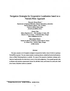
challenging and consists of surveying a “Wide-Area” of 10 nmi by 10 nmi in 100 hrs or less. Both of these demonstrations must be conducted while maintaining stringent navigation accuracy and contact localization requirements. 2 PLATFORMS The concept of operations for the CADRE system, Figure 2, relies on three types of autonomous underwater and surface platforms: • Communications and Navigation Aid (C/NA) vehicles, based on the Bluefin-21 UUV platform (a 21-inch-diameter vehicle) and the MIT Autonomous Surface Crafts; • Search-Classify-Map (SCM) UUVs, based on the Bluefin-12 platform (a 12.75” diameter vehicle); and • Reacquire-Identify UUVs, based on the Bluefin12 and Bluefin-9 platforms. These three vehicles (see Figure 1) can be employed in various combinations and configurations to execute a variety of missions of naval interest. The C/NA vehicles carry precision navigation suites, allowing them to navigate fully submerged for
serve as mobile beacon nodes in a novel moving long baseline (MLBL) navigation array. The SCM and RI vehicles use their acoustic modems as an LBL receiver for navigating off of the C/NA vehicles. Thus, the high-accuracy navigation of the C/NA vehicles can be passed on to the smaller vehicles. 3 MOVING LONG BASELINE (MLBL) NAVIGATION
Fig. 1: The Bluefin-21, Bluefin-12, and Bluefin-9 Autonomous Underwater Vehicles (AUVs). extended periods of time. While conducting an undersea survey, two (or more) C/NA UUVs/ASVs act as a mobile two-element LBL array and provide navigation solutions to the smaller SCM and RI UUVs, Figure 2. The SCM vehicles carry a suite of side-looking SAS and forward-looking sonars with which they detect mine-like targets on the seabed. When a target is detected, the SCM UUVs informs the C/NA via an acoustic communications channel. The C/NAs will then task an RI vehicle to reacquire and identify each target in real-time. In this manner, the whole chain of detection, classification, and identification of mine-like targets is executed in an “in-stride” fashion by the UUV cadre. The CADRE concept directly supports scalability of the system for larger search areas and/or more complex environmental or operational situations, such as increased clutter or target densities. In the CADRE concept of operations, each C/NA will carry a high-accuracy navigation system (INS-based for the UUVs and GPS-based for the ASVs) and will
2 C/NA x
SCM
x3
0 yd
s or
m or e
20
100
nm i
RI x 3
Fig. 2: CADRE Concept of Operations. The SCM vehicles use a SAS for wide-area coverage and an ahead look sonar (ALS) to fill the gap. The SCMs navigate relative to two or more C/NA vehicles. Each C/NA carries a high-performance navigation package. As Mine-Like Objects are detected and classified, the lead C/NA will task an RI UUV to investigate the contact. The RIs identify and mark the target, then speed back to the formation. Additional SCM and RI vehicles can be employed to increase the area coverage rate.
The C/NA UUVs will be fitted with an Inertial Navigation System (INS) and a Doppler Velocity Log (DVL). Given the operating depth and the bottom lock range of the DVL, the C/NAs will be able to maintain bottom lock at all times. A Kalman filter running onboard each C/NA will tightly couple INS and DVL data to provide a position estimate that drifts at a rate of about 0.1% of distance traveled. Position will be initialized on the surface using DGPS and occasional returns to the surface will be used to reset the position error accumulated underwater. The C/NAs will then able to bound their position error throughout the mission. The rate at which the C/NAs will surface to update their position will be determined by the absolute navigation accuracy desired for the mission. Considering a 3 m position error following the GPS update and a cruise speed of 3.5 knots, the C/NAs will need to surface approximately once an hour to maintain their position error below 10 m or about every 2.5 hours to maintain their position error below 20 m. The SCMs and RINs will carry a less accurate dead reckoning system based on a DVL and an Attitude and Heading Reference System (AHRS). The attitude and heading data will be calculated by complementary filtering of magnetic compass, angular rate and acceleration data provided by a Ring Laser Gyro (RLG) IMU and a magnetic compass. Although the SCMs will be equipped with a less accurate navigation system than the C/NAs and will never surface to update their position, they will still be able to bound their absolute position error by acoustically ranging to the C/NAs. When in the MLBL configuration, the C/NAs are positioned on the sides and at the rear of the cadre of vehicles to form the two-beacon moving baseline array that is used by the SCM and RI vehicles. All the vehicles will be synchronized to GPS time and will maintain accurate synchronization when submerged. With time synchronization, an unlimited number of SCM and RI vehicles can determine their range to the C/NAs by listening only. The only requirement is that the C/NAs’ ping time be known by the SCM and RI vehicles. This can be done by pre-scheduling ping times or informing the cadre of vehicles of the ping sequence through an initialization broadcast. Time synchronization has the additional advantage that all the data logged in different vehicles are referenced to the same time base. Therefore, all the data can be used in postprocessing to improve the real time navigation (renavigation).
ranging and communications capabilities, without the complexity of having three AUVs in the water at the same time (Curcio, et. al. 2005). Results from this experiment, conducted with a Bluefin-12 and two MIT ASVs in 2006, are reported below.
Fig. 3: The CADRE Moving Long Baseline navigation cycle timing. Each SCM and RI vehicle runs its own local navigation filter to predict its position based on dead reckoning data and corrects this prediction by using ranges to the C/NAs whenever they are available. A MLBL navigation cycle is shown in Figure 3. C/NA1 pings at a time known by all the vehicles and broadcasts its position at the time of the ping. Upon reception of the ping, the vehicles are able to calculate their range to C/NA1. A few seconds later, the vehicles receive the position of C/NA1. The range to C/NA1 can then be used to correct the position of the vehicles along the direction between them and C/NA1. C/NA2 then pings at its predefined time. The vehicles determine their range to the C/NA and receive its position. They can then update their position along the direction between them and C/NA2. The navigation algorithm running in the SCM and RI vehicles will be capable of: 1) accounting for delays between the range measurement and the reception of the C/NA’s position, 2) estimating navigation error sources, 3) rejecting outliers in the range measurements, and 4) re-initializing the filter if necessary. This approach, where every vehicle runs a navigation algorithm that is independent of the other vehicles, is considered to be the simplest option because: it is very similar to classical LBL except that the position of the “transponder” changes with time, it only requires the ranges to the C/NAs (no inter SCM/RI ranges), it makes minimal use of acoustic communications for the purpose of navigating, it allows to not have to account for cross-correlations when using acoustic ranges, and it can still be used without time synchronization. 4 MLBL EXPERIMENTAL RESULTS An MLBL experiment was conducted in 2003 that involved a Bluefin-21 AUV and two boats serving as surrogate C/NAs (Vaganay, et. al., 2004). The data collected during these experiments allowed us to develop the MLBL navigation algorithm to be used onboard the SCMs for CADRE. However, this experiment did not include any acoustic communications. As an intermediate step to operations involving AUVs only, MIT developed autonomous surface vehicles to be used as surface C/NAs. This approach allowed us to test the acoustic
The two ASVs were anchored, 140 m apart, in an area about 17 m deep. ASV1’s acoustic modem transducer hung about 5 meters below the surface in a tow fish, while ASV2’s transducer only hung about 1.5 m deep. The AUV ran lawnmower patterns on one side of the baseline defined by the ASVs, first with the ASVs just floating at their mooring, then with the ASVs thrusting around their anchor point. Only the results obtained with the ASVs thrusting are presented since we could not see any substantial difference in acoustic communication performance between the two runs. The use of the ranges to the ASVs was disabled at the time of these tests, so that the vehicle dead reckoned the whole time while collecting all the MLBL data. The data set has been post-processed using the same navigation algorithm, but with integration of the acoustic data in the navigation solution. Unfortunately, a damaged connector affected ASV2’s reliability and only a limited amount of data was obtained from ASV2. The ranging schedule was as follows: at time t, the AUV pinged ASV1 and waited for a reply that provided the range to ASV1. A few seconds after replying to the interrogation, ASV1 transmitted its GPS position to the AUV. At time t+20 seconds, the AUV pinged ASV2 and waited for a reply that provided the range to ASV2. A few seconds after replying to the interrogation, ASV2 transmitted its GPS position to the AUV. At t+40 seconds, the AUV broadcasts its estimated position to the ASVs, which relayed it by WiFi to the ship for display. At t+60 seconds, the AUV pinged ASV1 again, etc. Ranges were typically available to the AUV 7 seconds after the AUV pinged. An additional 5 seconds were needed for the AUV to get the position of a ASV. Therefore, although 20 seconds were allocated for a cycle to a ASV, only about 12 seconds were actually needed. During a given cycle, the AUV would either measure a range and get position information from the ASV, measure the range only, receive the position information only, or would not able to measure a range nor to receive position data. During each mission, the vehicle was able to ping each ASV 16 times. Figure 4 shows the AUV’s dead reckoned trajectory and the GPS position of the ASVs. Red and black are used to represent cycles to ASV1 and ASV2, respectively. In this figure, AUV1 and AUV2 are labeled K0 and K1, respectively. Each symbol on the trajectory represents the AUV’s position at the AUV ping time of the cycle and identifies the amount of data collected for that cycle. Figure 5 shows the AUV’s dead reckoned trajectory as well as the position calculated by the MLBL navigation algorithm in post-processing (use of acoustic data enabled). The algorithm made use of all
Fig. 4: AUV dead reckoned trajectory (solid blue). ASV1 position (red stars). ASV2 position (black stars). the full cycles to ASV1 and ASV2. However, since the data relative to ASV2 were very sparse, the AUV’s position is not well constrained in all directions. The position estimate is mostly influenced by ASV1, so that there is a better position correction along the North-East/South-West axis than perpendicularly to that axis. Additional tests are underway at the time of this writing. The tests will focus on characterizing the performance of the modem in terms of range versus water depth. Real-time static LBL relative to two anchored ASVs will first be performed, followed by Moving Long Baseline where all the assets move along tracklines. 5 AUTONOMY For teams of AUVs to be truly effective, they must be capable of autonomously executing heterogeneous multi-vehicle plans. It is desirable that vehicles be able to self-synchronization when appropriate, manage communications resource constraints and keep the operator in-the-loop while doing so. Group autonomy does not necessarily mean a complete lack of operator involvement – the human operator plays a key role in the functioning of the team. It is rather a question of providing to the operator the level of information and an interface that is most relevant to the task at hand. Our approach to autonomy involves providing individual AUVs with the capability to flexibly execute mission plans, allowing teams of AUVs to transmit the appropriate level and amounts of information for effective coordination, and involving the user in this process as much as possible. Vehicle teams should not be bound by static plans. Execution of plans should be sufficiently flexible to allow the team to coordinate its activity in response to dynamic situations. Team members know when to seek authority from an operator or other vehicle to execute their plans. Teams should be resilient to both communications problems and attrition. Each team member may be capable of performing its own noncollaborative tasks, or if not, has some mechanism for signaling an inability to continue with its task
Fig. 5: Filtered MLBL trajectory using ranges to ASVs. based on a coordination failure with other team members. The level of autonomy exhibited (and consequently the degree of independent execution flexibility available to the team and its level of collaboration with the human users) should be adjustable to fit the mission or sub-mission requirements. Such intelligent autonomy leads to efficiency and robustness in the face of failures and communications loss. In order to realize such heterogeneous, autonomous multi-vehicle capabilities, vehicles must have unique identities and be aware of their individual capabilities and their role as team members. Simply assigning tasks based on identity, however, is not sufficient to ensure the successful completion of a mission. If a task is mis-assigned or its constraints are not within a vehicle' s capabilities, the task will fail and likely have a ripple effect on other team members, potentially jeopardizing the entire mission. When plan exigencies involve synchronization and coordination with other vehicles or the operator, an understanding of the team and its overall mission can help manage team performance. One method to add robustness to multi-vehicle coordination is to structure the interaction and communications necessary for such coordination around behavioral capabilities rather than around atomic actions. If, for example, one AUV wishes to request of another AUV in the team that it survey a particular rectangular region, it can do so in a variety of ways. In one possible system, it can specify the set of movements required to accomplish the task. This requires a detailed understanding of the workings of one team member by another, and may be extremely brittle as even slight inconsistencies could lead to mission failure. On another system, the requesting vehicle could simply specify the region to be surveyed and the type of information required. It is up to the assigned AUV to determine the best method to accomplishing the task. It is also important to ensure distributed coordination of the team with the limited and intermittent communication possible between the vehicles. These
communication constraints limit the situational awareness, leading to incomplete and inconsistent information across the vehicles, possibly resulting in conflicting behavior that reduces team efficiency and can even lead to mission failure. The more data that has to be transmitted between vehicles to establish the coordination mechanism and the appropriate level of situational awareness, the more problematic communication constraints will be. This is an additional argument for limited, high-level communications (i.e., in terms of capabilities rather than actions). Synchronization mechanisms also require structuring to make them robust to communications difficulties. A major effort of ours is developing behavior and autonomy software to provide vehicles with the required execution flexibility to effectively modify and coordinate the activity in a team. Improved individual and team autonomy also reduces the burden placed on the operator by allowing vehicles to manage many of the details of mission plan execution and only occasionally request/require assistance depending on mission parameters. We have recently developed (and are now testing) a new “behavior control” system, essentially a highly flexible executive responsible for accomplishing elements specified in a mission plan. This new Behavior Control (BC) system greatly facilitates dynamical insertion, removal and modification of mission elements during execution. This is a vital capability for effective coordination of multiple AUVs (and the human operator) in the typically uncertain and noisy environment of these systems. Mission plans are viewed as guidelines for execution. Actual execution of plans in the physical world may require more/less time than planned (perhaps due to currents), may have varying degrees of navigation accuracy, and may encounter acoustic communications problems. The mission plan does not fully account for these exigencies and thus requires flexibility of execution to account for them, especially when synchronized coordination across multiple vehicles is required. Our BC system will also provide the framework for more complex replanning and retasking of vehicles due to this execution flexibility. Consider the example of an SCM class AUV that encounters a contact that merits further investigation and creates new RI tasks for a different RI-capable AUV. The RI AUV must be able to suspend its current tasks and execute the new RI tasks, resuming its previous tasks when finished.
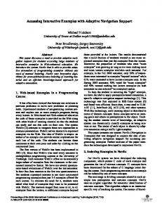
Fig. 6: The Bluefin Mission Planner application is a chart-based, “point-and-click” graphical interface for all aspects of UUV mission planning. operator increases, so does the risk of operator overload. Thus, it is critical to develop interfaces that readily enable operators to understand the status of multiple vehicles and interact with them effectively and efficiently, all while maintaining high levels of situation awareness and limiting the risk of operator overload. Interfaces must be carefully designed to provide pertinent status, goal and alert information, as well as command and control operations. The operator must be able to assess quickly and accurately the status of a mission in order to decide on a course of action. More detailed information should quickly be available when required, and hidden when not. This means that the operator will have multi-resolution views of the individual vehicles (and the mission) containing different alerts, data (or data abstractions), and operations. For example, at a high level, the operator will be able to evaluate mission plan execution, or, at a lower level, examine a particular vehicle' s health. Our Operator Tools (Figures 6 and 7)are designed with the operator foremost in mind, proving the right information at the right level of detail to quickly assess the situation, while also supporting the ability to “drill down” and get more detailed information as needed. Current multi-vehicle capabilities for our Operator Tools include the monitoring of multiple AUVs (and other track-able assets such as surface ships) in a single chart-based interface. A planned future enhancement is the ability to control multiple AUVs from a single interface.
6 USER INTERFACES
7 INTEGRATION OF AUTONOMY AND USER INTERFACE CAPABILITIES
In order to have command and control of vehicles and be able to collaborate intelligently with the vehicles, the operator must have a user interface that provides information and tools at the correct level of abstraction and detail. Cognitive overload is a serious impediment to user efficiency and mission success. As the number of vehicles controlled per
Given vehicles that are able to coordinate as a team and user tools and interfaces that facilitate control by and collaboration with the operator, the missing element that ties these together and enables team collaboration and control is the data that is exchanged. Team and individual plans must be sent from the operator control station (OCS) to the
broken down into individual tracklines, waypoints, etc., for mission execution but this level of detail need not be specified in the plan. The high-level representation thus provides an excellent substrate for communication of mission plans (for initial execution, re-tasking, etc.) across bandwidth limited (e.g., acoustic) channels. 8 DEMONSTRATIONS
Fig. 7: The Dashboard User Interface gives the operator critical situational awareness. vehicles, and between the vehicles themselves, for the purposes of message relaying and replanning. Vehicle health and status information, in addition to mission-directed intelligence/data, must also be communicated between vehicles and operators. Even when all of the vehicles and OCS’s understand the nature of the data being sent and its implications (both individually and to the team' s goals) there still exists a number of complicating issues. One significant issue is that communications may be unreliable, slow, or even non-existent (for example when AUVs are submerged) for periods of time. Individual vehicles and the team must account for and robustly handle communications/bandwidth losses without creating brittle mission failures. In addition, there must be an understanding of the types and amounts of data that are required to be sent between the different elements of the team, as well as optional data that can be sent if communications constraints allow. Data must also be refined and abstracted as appropriate. This is particularly important to the operator, who should not be inundated with unnecessary detail. A goal of ours is developing a data model appropriate for team collaboration and control in the face of mission and communications limitations and constraints. This goal has been accomplished in our system using two mechanisms. The first is a communications infrastructure called SOMA that provides different priorities for messages sent within the system. Messages may be reliably or unreliably sent. In addition, each communications channel (acoustic, RF, Ethernet) can be tailored to limit the data that are transmitted so as to make most effective use of the bandwidth available. A second mechanism is our mission plan representation. We have recently moved from a flat representation for missions (basically a list of mission elements) to a hierarchical representation allowing very concise representations of highly complex mission elements. A lawnmower survey, for example, can be represented at a high-level simply by specifying the rectangle defining the area to be surveyed. This high-level representation can be
To demonstrate our autonomy capabilities in the context of the CADRE concept, we plan to run a minimum of three vehicles: two C/NA (Communication/Navigation Aid) vehicles and at least one SCM (Search, Classify, Map) vehicle. In this scenario, one of the C/NA vehicles will be the leader, responsible for the coordination and synchronization of the team members. The leader will be assigned the overall mission and will be responsible for assigning tasks to the other team members in order for the overall group mission to be accomplished. The vehicles will first run a short mission to reach their respective start positions, establishing an appropriate initial formation. When all the vehicles are in place, the actual mission will be started. The mission will consist of one long trackline, or possibly several parallel tracklines. One of the C/NA vehicles will be the “leader” responsible for assigning tracklines to the other vehicles and coordinating execution of the mission. During these tracklines, the SCM vehicle will dead reckon and integrate acoustic ranges to the C/NAs in their navigation solution. The C/NAs will also dead reckon but occasionally come back to the surface to reset their position by GPS. During these position resets, the SCMs will loiter underwater and resume their surveys when the C/NAs dive and the leader instructs the group to proceed. ACKNOWLEDGEMENTS The authors would like to thank the Office of Naval Research of the US Navy who supported this research under contract number N00014-02-C-0204. REFERENCES Vaganay, J., J.L. Leonard, J.A. Curcio, and J.S. Willcox (2004), Experimental Validation of the Moving Long Base-Line Navigation Concept, Proceedings of the IEEE Oceanic Engineering Society AUV 2004 Conference, CD Proceedings, Sebasco, Maine, June 17-18, 2004 Curcio, J.A., J. Leonard, J. Vaganay, A. Patrikalakis, A. Bahr, D. Battle, H. Schmidt, M. Grund (2005) Experiments in Moving Baseline Navigation using Autonomous Surface Crafts, Oceans 2005, CD Proceedings, Washington DC, Sept. 2005