Jul 20, 2011 - A CDN is graphical model for cooperative decision by multiagent, proposed for supply chain industrial design. Each agent Ai carries a subnet ...
July 20, 2011 16:36 WSPC/INSTRUCTION FILE
jnl-expl
Multiagent Expedition with Graphical Models
Yang Xiang and Frank Hanshar School of Computer Science, University of Guelph, Canada We investigate a class of multiagent planning problems termed multiagent expedition, where agents move around an open, unknown, partially observable, stochastic, and physical environment, in pursuit of multiple and alternative goals of different utility. Optimal planning in multiagent expedition is highly intractable. We introduce the notion of conditional optimality, decompose the task into a set of semi-independent optimization subtasks, and apply a decision-theoretic multiagent graphical model to solve each subtask optimally. A set of techniques are proposed to enhance modeling so that the resultant graphical model can be practically evaluated. Effectiveness of the framework and its scalability are demonstrated through experiments. Multiagent expedition can be characterized as decentralized partially observable Markov decision processes (Dec-POMDPs). Hence, this work contributes towards practical planning in Dec-POMDPs.
1. Introduction We consider a class of multiagent planning problems which we term multiagent expedition. A typical instance consists of a large open area populated by objects as well as mobile agents. Activities of agents include moving around the area, avoiding dangerous objects, locating objects of interests, and manipulating objects. The outcome of an action is generally uncertain. Agents have no prior knowledge of the area. Instead, they try to identify nearby objects based on limited sensing of the local area. Successful manipulation of an interesting object sometimes requires proper actions of a single agent and sometimes requires cooperation of multiple agents. The success of an agent team is evaluated based on the quantity of objects successfully manipulated as well as the quality of each manipulation. Practical examples of multiagent expedition are abundant. In planetary expedition, interesting objects include rocks of certain physical or chemical compositions. Cooperation is needed to collect rocks when one robot is specialized in digging and another is specialized in carrying. In disaster rescue [14], target objects include victims trapped in wreckage. In order to rescue them, some rescuers may lift and hold heavy building components while others pull the victims into safety. Multiagent expedition is a subclass of Dec-POMDPs which are highly intractable. Oliehoek et al. commented in [20]: “Unfortunately, optimally solving Dec-POMDPs is NEXP-complete, and the same holds for finding an �-approximate solution. As a result, research has focused on special cases to overcome this complexity barrier.” One testimony is that many experimental studies are limited to artificially constructed testbeds with two or three agents, e.g., [3, 10, 20, 23]. We take the same approach in this work. The design of successful agent teams 1
July 20, 2011 16:36 WSPC/INSTRUCTION FILE
jnl-expl
in multiagent expedition is a challenging task (see [7]) and requires more than a few steps of advancements. To carry out an algorithmic and experimental study, we abstract the essential characteristics of multiagent expedition into a specific type of environment for the current investigation. We demonstrate that our solution allows us to experiment with agent teams of sizes well beyond two or three. Lessons learned from our computational solution to the special case promise to be the springboard to solutions of more general cases. Most research on Dec-POMDPs, including those that explore factorized representations, focus on offline policy making, e.g., [20,23]. Few, e.g., [5] (non-graphical model) and [10] (loosely coupled graphical models), have focused on online planning. This work takes the approach of online planning. That is, agents will cooperate to compute the best plan based on current observations for immediate execution. The environment used in this study is represented as a grid of cells. The general problem of planning for optimal performance in this environment is shown (Sections 2 and 3) to be highly intractable. We therefore handle multiagent expedition over an extended time period through a sequence of (coherent) planning sessions each of which is over a limited horizon. These planning sessions are interleaved with executions of resultant plans. We propose a set of techniques to decompose the planning task to a set of semi-independent optimization subtasks, and to ensure that such planning is conditionally optimal (elaborated below) and is under reasonable runtime. We experimentally demonstrate the effectiveness of these techniques. The core knowledge representation used by agents is based on a multiagent graphical model, called collaborative design networks (CDNs) [30, 31]. CDNs were originally proposed for decision-theoretic, multiagent, optimal industrial design. The expressive power of the framework, however, goes beyond industrial design. We propose techniques that allow each agent group to encode their planning knowledge into such graphical structures. In an earlier work [32], multiagent expedition was used as testbed. The objective of the study was to compare two fundamentally different decision paradigms, rather than to solve multiagent expedition generally. The techniques considered for solving multiagent expedition were limited, not scalable (e.g., group size is limited to three), and were not analyzed. The current work presents a set of techniques with formal analysis on their conditional optimality and efficiency impact, and provides a scalable solution to multiagent expedition with extensive experimental results. More related work is discussed in Section 13. 2. The Multiagent Expedition Testbed To carry out algorithmic and experimental study, we abstract the essential characteristics of multiagent expedition into the following specific type of environment for the current investigation. A large open area is abstracted as a grid of cells. Time is discretized and, at each instant, each agent must take an action. At any cell, an agent has five possible actions: moving to an adjacent cell along one of four 2
July 20, 2011 16:36 WSPC/INSTRUCTION FILE
jnl-expl
directions (referred to as north, south, east, west) or remaining in the current cell (referred to as halt). The outcome of an action is, however, uncertain. That is, the action north may cause the agent to land on each of the four unintended cells. The only exception is the action halt, which is deterministic. We assume that when an agent lands on a particular type of cell, a particular type of activity is performed. Sampling a rare rock on Mars is a desirable activity that can be performed when such a rock is encountered. Saving an earthquake victim is a desirable activity that can be performed when the victim is reachable. A cell may have nothing interesting. Simply passing by such a cell is a neutral activity. A cell may contain an obstacle and hence passing by is harmful. The desirability of an activity performed at a cell is evaluated by a numerical reward. For generality, we abstract away the activity, associate the reward with each type of cells, and refer to it as the reward of a cell. A neutral cell (neither desirable nor harmful) has the reward of a base value β. The reward of a harmful cell has a value lower than β. The reward of a desirable cell has a value higher than β and can be further increased through agent cooperation (defined as two or more agents landing on the cell at the same time). We assume that the value of reward is in the range [0, 1], where 1 corresponds to the most desirable and 0 the least. One primary purpose of multiagent systems is to benefit from cooperation. However, agents do not need to cooperate at all time (sometimes, working as individuals may be more productive). Nor does it always require involvement of the entire agent team when cooperation is indeed beneficial. For instance, when a physical activity is performed at a given location (e.g., digging, lifting, pushing, etc.), cooperation is often most productive when a certain number of agents are involved. The per-agent productivity is reduced when more or less agents are involved. Hence, an effective multiagent system should allow agents to operate individually or cooperate at the right level as the situation demands. To enable investigation of this behaviour, our experimental environment rewards agents accordingly. First, we differentiate between productive and unproductive cooperation. An environment is associated with a parameter λ ∈ {2, 3, ...}, called the most productive level of cooperation. The reward received by an agent at a desirable cell suited for cooperation, when several agents cooperate and meet at the cell, is defined as follows. Its properties are summarized in Proposition 1, whose proof is straightforward. Definition 1. Let c be a desirable cell suited for cooperation, r1 be the reward if exactly one agent lands on c, and r2 be the reward if λ agents meet at c. Let x be the total number of agents who meet at c. Then each agent receives the reward r: r1 > β : x=1 r > r : x=λ 2 1 r= x−1 r1 + λ−1 (r2 − r1 ) : 1 < x < λ r2 −β β + x−λ+1 : x>λ Proposition 1. The reward each agent received according to Def. 1 satisfies the 3
July 20, 2011 16:36 WSPC/INSTRUCTION FILE
jnl-expl
following properties: (1) The function r(x) is continuous in [1, +∞). (2) When x < λ, r increases as x increases. (3) When x > λ, r decreases as x increases, but is lower-bounded by β. (4) When x = λ, r is maximal. Statement (1) says that, as the number of meeting agents changes, the reward received per agent changes smoothly. Statement (2) says that, as the number increases towards the most productive level, the reward received per agent increases as well. Statement (3) asserts that, once the number exceeds the most productive level, the reward received per agent decreases, but the cell remains desirable. Statement (4) asserts the most productive level of cooperation. This environmental property differentiates between productive and unproductive cooperation, promotes the former, and discourages the latter. Furthermore, we allow cells where cooperation is not favourable. Such a cell is also characterized by parameters (β, r1 , r2). However, r2 satisfies β < r2 < r1 . As a result, when a single agent moves to the cell, it receives reward r1 . If more agents meet at the cell, each receives less than r1. After a desirable cell has been visited by any agent, its associated reward is decreased to β. This property conveys the intuition that after useful rocks at a location have been collected, visiting this same location becomes a neutral activity. As a result, wandering around a neighbourhood is unproductive and agents are motivated to migrate strategically. On the other hand, after a harmful cell is visited, its associated reward is unchanged. Agents have no prior knowledge about how different types of cells are distributed in the environment. Instead, at any cell, an agent can perceive its absolute location
C
A
c
A
B
A
B
(a)
(b)
(c)
(d)
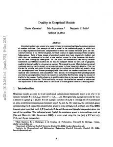
Fig. 1. (a) A neighbourhood perceivable by an agent. (b) A group formation where the group direction is indicated by the arrow. (c) Illustration of Proposition 3. (d) A and B plan to meet at cell c in 2 steps. A halts first to avoid moving to c alone.
(e.g., through GPS on Earth or triangulation with two base stations on Mars). It can also perceive the types of cells in a given radius ρ and assess reliably the reward of each cell. For example, a neighbourhood of radius ρ = 2 steps is shown in Fig. 1 (a). An agent can perceive the location of another agent if the latter is within a specified radius γ. It can only communicate with agents within this radius as well. The objective of agents is to move around the environment, cooperate as appro4
July 20, 2011 16:36 WSPC/INSTRUCTION FILE
jnl-expl
priate, and maximize the total team reward over a finite horizon k where 1 < k ≤ ρ. They must do so based on local observations and limited inter-agent communication. Note that it is possible that team agents A1 and A2 are within the distance ρ (or γ), so are A2 and A3 , but the distance between A1 and A3 is beyond ρ (or γ). Dimensions of a congregate of harmful cells have a significant impact on effective planning. Congregates of large dimensions are rare in open areas and we do not consider them in this work. That is, we assume that the sum of x-dimension and y-dimension of the largest congregate is less than k. Formally the environment described above is a tuple (Ag, S, ∆, T r, R, Ob, st0, k). • Ag = {A1 , ..., An} is a team of n agents. • Although the multiagent expedition environment is generally open, for planning with a finite horizon, the relevant region is finite. S denotes the finite set of states of this region. Each state st ∈ S is described by a pair st = (ps, ct). The ps is the team configuration, ps = (psA1 , ..., psAn ), where psAi is the position of agent Ai . The ct is the cell type distribution that, for each cell in the region, specifies its type. • ∆ = ×i ∆i is a set of joint actions and ∆i = {north, south, east, west, halt} is the set of actions available to Ai . At each time step, agents take one joint action δ = (mvA1 , ..., mvAn ) ∈ ∆, where mv denotes movement. • The transition probabilities P (st0|st, δ) are specified by the transition function T r. Note that a state transition includes not only the position transition of agents, but also the cell type transition, because once a desirable cell has been visited, its associated reward is reduced (a type transition). • R = (R1(ct, ps0 ), ..., Rn(ct, ps0 )) is the immediate reward function, where Ri (ct, ps0 ) is the immediate reward of Ai given the previous state (ps, ct) and the current state (ps0 , ct0). Note that ct determines the type for cell ps0Ai and hence the pair (r1 , r2) of parameters in Def. 1. The ps0 determines how many agents (x in Def. 1) meet at ps0Ai . From r1, r2 and x, Ri (ct, ps0) is determined by Def. 1. • Ob = ×i Obi is the set of joint observations at time 0, where Obi is the observation of Ai that includes only the positions of agents and types of cells in its current neighbourhood (a small area within the region). Although Ob is partial, we assume that it is reliable. That is, observed agent positions and cell types by each Ai is correct. • The initial state at time 0 is st0 . It is unknown to agents (but partially observable). The planning horizon is k. Note that since we are interested in online planning, rather than offline policy making, st0 and Ob are fixed rather than probabilistically specified. The above multiagent expedition environment can be characterized as decentralized partially observable Markov decision process (Dec-POMDP) [4]. The state of the environment is described by the positions of agents and the cell type distribution. It is stochastic since the outcome of agent actions are uncertain. It is 5
July 20, 2011 16:36 WSPC/INSTRUCTION FILE
jnl-expl
Markovian as the new state is independent of the history conditioned on the current state and the joint action of agents. It is partially observable because each agent can only perceive its neighbourhood, but not cells and other agents beyond. 3. The Multiagent Online Planning Problem Denote action of Ai ∈ Ag at step j (1 ≤ j ≤ k) by mvAi ,j . A joint plan of horizon k contains a movement for each agent in each of the k steps, and is denoted (mvA1 ,1, ..., mvAn,1 , ..., mvA1,k , ..., mvAn,k ) = (δ1 , ..., δk). | {z } | {z } n terms
n terms
i
Denote the position of A after the j’th action by psAi ,j . A team configuration after the j’th joint action is psj = (psA1 ,j , ..., psAn,j ) and a team configuration sequence after the execution of a joint plan (k steps) is (psA1 ,1, ..., psAn,1 , ..., psA1,k , ..., psAn,k ) = (ps1 , ..., psk). | {z } | {z } n terms
n terms
Next, we specify the payoff from the outcome of a joint action. In the literature on POMDPs, the reward is normally assumed (perhaps implicitly) objective (versus subjective) and the goal of planning is to maximize the accumulative reward, possibly discounted [6]. Our approach is a departure from this common practice, and is consistent with Bayesian decision theory and its adoption in CDNs. We define the utility function for the team over team configuration sequences and denote by ψT ,1...k(ps1 , ..., psk) ∈ [0, 1], where T stands for team. For most team configuration sequences, the utility is defined based on the accumulative reward 1 XX ψAi ,j , nk n
ψT ,1...k(ps1 , ..., psk) =
k
(1)
i=1 j=1
where ψAi ,j is the reward that Ai received at jth step at cell psAi ,j . Situations where the utility values differ from the above and their advantage will be presented in Section 10. For simplicity, we have assumed equal weight for all agents without discounting, although this does not have to be the case for our result to hold. The team expected utility for a joint plan of horizon k is X X EUT ,1...k(δ1 , ..., δk) = ... ψT ,1...k(ps1 , ..., psk)P (ps1, ..., psk|δ1, ..., δk), (2) ps1
psk
where P (.|.) denotes the probability of a team configuration sequence resultant from the joint plan and the summation is over all such sequences. For simplicity, we will P P P write ps1 ,...,psk in place of ps1 ... psk . Although P (ps1 , ..., psk|δ1, ..., δk) is not directly specified by T r, it can be derived from T r as we will show in Section 6. Furthermore, evaluation of ψT ,1...k(ps1 , ..., psk) is conditioned on observation Ob. The multiagent online planning problem is to find an optimal joint plan (δ1∗ , ..., δk∗) that satisfies the following given observation Ob: EUT ,1...k(δ1∗ , ..., δk∗) = max EUT ,1...k(δ1 , ..., δk). δ1 ,...,δk
6
(3)
July 20, 2011 16:36 WSPC/INSTRUCTION FILE
jnl-expl
At each step, each agent has five possible actions. Hence, there are 5n joint actions and 5nk joint plans of horizon k. Since each action has five possible outcomes, a joint action has 5n possible team configurations. This means that the summation of Eqn. (2) is over 5nk terms, each of which corresponds to a possible team configuration sequence of the same joint plan, whose probability and utility must be evaluated. To solve Eqn. (3), Eqn. (2) must be computed once for each of the 5nk joint plans, which amounts to evaluation of a total of 52nk possible team configuration sequences: an intractable task. For example, if n = 6 and k = 2, a total of 524 ≈ 6 × 10¹⁶ team configuration sequences need to be evaluated. To practically carry out the task, we take a decision-theoretic graphical model approach and propose a set of techniques. Section 4 groups agents to decompose team plan into group plans. After a brief background on CDNs in Section 5, we focus on graphical modeling of the problem as CDNs in Section 6. Section 7 constraints group plans through a group organization. Section 8 restricts agent directions to better coordinate a group. Section 9 discards halt option in some action sequences to improve efficiency. Sections 10 and 11 promote desirable team formations. 4. Grouping Agents Within A Team The first measure we consider is to divide a team of n agents into smaller groups in order to gain planning efficiency. Cooperation will only be attempted within a group. To ensure that group members can cooperate at the most productive level whenever opportunities arise, we enforce Assu. 1 on group size: Assumption 1. Let g denote the size of any agent group. Then, g ≥ λ. For simplicity of presentation, groups are assumed to have the same size g, although this is not needed for our results to hold. In this work, we assume that λ is given and is fixed. Hence, agent grouping is determined at compile time. Next, we assume that team configurations satisfy certain formations. These formations allow more efficient planning and will be actively enforced through planning. Assu. 2 below requires the distance between each pair of group members to be less than γ, so that group members are able to communicate. This allows them to perform distributed planning using techniques in Section 5. Assumption 2. At any time, group members are within the distance γ to each other. Another condition below requires that no agent outside a group is closer than 2k distance with any group member. Note that since time and space are discretized in steps and cells, respectively, an agent moves a maximum 2k distance in 2k time. Assumption 3. At any time, two agents from distinct groups are at least 2k + 1 distance apart. Assu. 3 implies that members of distinct groups cannot interact as far as their rewards are concerned. This is because the only interaction that can directly affect 7
July 20, 2011 16:36 WSPC/INSTRUCTION FILE
jnl-expl
their rewards is to meet at the same cell. Meeting becomes impossible when their distance ≥ 2k + 1, even if they move towards each other for k steps. How to enforce Assu. 2 and 3 are presented in Section 10. Given Assu. 1 through 3, Eqn. (2) can be written as gX EUT ,1...k(δ1 , ..., δk) = EUG,1...k (δ1G , ..., δkG) (4) n G
where the summation is over the n/g groups, denoted by group index G, and δjG is the jth step joint plan for the Gth group. Each term in the summation is the group expected utility defined as X G G G G G EUG,1...k (δ1G , ..., δkG) = ψG,1...k(psG 1 , ..., psk )P (ps1 , ..., psk |δ1 , ..., δk ), G psG 1 ,...,psk
(5) where psG j is jth step configuration of Gth group, and group utility is defined as G ψG,1...k(psG 1 , ..., psk )
g k 1 XX = ψAi ,j , gk i=1 j=1
(6)
where Ai is the ith agent in the Gth group. We refer to a group plan (δ1∗G , ..., δk∗G) as conditionally optimal under Assu. 1 through 3, if the following holds under these assumptions: EUG,1...k (δ1∗G , ..., δk∗G) = max EUG,1...k(δ1G , ..., δkG) G δ1G ,...,δk
(7)
We refer to a team joint plan (δ1∗ , ..., δk∗) as conditionally optimal under Assu. 1 through 3, if Eqn. (3) holds when Assu. 1 through 3 are satisfied. The above analysis shows that under Assu. 1 through 3, conditional optimal team planning can be replaced, by conditional optimal group planning conducted asynchronously by individual groups. Suppose n = 6, g = 3 and k = 2. Each agent now needs to evaluate 512 ≈ 2.4 × 10⁸ possible outcomes. This reduction, from 6 × 10¹⁶ above, is due to not having to evaluate inter-group interactions. The conditional optimality and efficiency gain of grouping are summarized in the following proposition, whose proof is straightforward given the above analysis. Proposition 2. Let a team of n agents plan for horizon k, in an environment where the most productive level of cooperation is λ and the maximum direct communication distance is γ. Let the team be divided into groups of g agents such that Assu. 1 through 3 are satisfied. Then, the following hold: (1) Any set of conditionally optimal group plans is a conditionally optimal joint plan. (2) Time complexity of planning at each group is upper-bounded by O(52gk ). The O(52gk ) complexity can be viewed either as a bound for a centralized planning agent one per group, or as a bound for each group member in distributed planning. It will be reduced in Sections 6 and 7 with distributed planning based on graphical models. 8
July 20, 2011 16:36 WSPC/INSTRUCTION FILE
jnl-expl
An additional consequence of Assu. 3 is that a team works more effectively when groups are dispersed over a broader region, rather than packed into a narrow area. Finally, such grouping can scale up as n grows. In summary, grouping effectively decomposes the optimization task into semiindependent optimization subtasks, one per group. They are ‘independent’ as optimization is now within each group. They are ‘semi’ because group planning must maintain both inter and inner-group distance, which is elaborated in Section 10. 5. Background on CDNs Core knowledge representation used in this work is the CDN, due to its expressive power as a multiagent decision-theoretical graphical model and an associated set of sound and effective inference algorithms. Below, we introduce background on CDNs. For more details, see [28] on multiagent graphical models and [29–31] on CDNs. A CDN is graphical model for cooperative decision by multiagent, proposed for supply chain industrial design. Each agent Ai carries a subnet that is equivalent to an influence diagram, whose nodes includes design parameters (denoted Di ), performance measures (M i), and utilities (U i ). They are drawn as squares, ovals, and diamonds, respectively. Generally, a utility node can only have performance parents, and a performance node can only have design parents. Each utility variable u with parents π(u) is associated with a domain {y, n} and a function u(π(u)) ∈ [0, 1] encoded as P (u = y|π(u)). Agents are organized into a hypertree, which specifies direct communication pathways. Each pair of adjacent agents share a set of public design parameters, called an agent interface. A message between them is either a utility function or an assignment over the interface. Additive independence [12] among utility variables is assumed. Each utility is assigned a weight in [0, 1] such that weights of all utility nodes in U i sum to one. Each subnet is assigned a weight in [0, 1] such that weights of all subnets sum to one. These weights express relative importance of each utility and relative importance of each agent’s preference. The expected utility of a design d is X X X EU (d) = wi κij ( uij (m) P (m|d)) , (8) i
m
j
where d is a configuration over ∪i Di , i indexes subnets, j indexes utility nodes {uij } in ith subnet, m is a configuration of parents of uij , κij is the weight assigned to uij , and wi is the weight assigned to ith subnet. Through message passing among agents, the globally optimal design d∗ that maximizes EU (d) can be obtained exactly. Although CDNs were originally developed for design, their expressive power is beyond design: Design parameters may be generic decision variables. Performance measures may be generic variables describing properties of agent environment. This generality renders CDNs applicable to modeling in the current work as shown below. 9
July 20, 2011 16:36 WSPC/INSTRUCTION FILE
jnl-expl
6. Graphical Modeling With grouping, conditional optimal team planning amounts to optimal group planning, which requires evaluating group plans according to Eqn. (5). Consider space complexity for storing planning information in Eqn. (5). A group plan can be represented by a matrix of dimension g × k. From an initial group configuration, there are 5gk group plans that has a space complexity of O(g k 5gk ). A possible outcome of a group plan is a group configuration sequence, which can also be represented by a matrix of dimension g × k. Each group plan has 5gk such possible sequences. The space complexity of all outcomes of all group plans is then O(g k 52gk ). Associated with each outcome matrix are its utility and its probability conditioned on the group plan. They occupy an O(2 × 52gk ) space. For an example, suppose g = 3 and k = 2. Plan matrices need a space of size 93,750 and outcome matrices need a space of size 1,464,843,750. Utilities and probabilities need a space of size 488,281,250. Total space required has a size of 1,953,218,750. We show below that planning knowledge can be more effectively encoded with a CDN. The utility ψAi ,j in Eqn. (6) formally depends on the group configuration seG quence (psG 1 , ..., psk ). Since utility at a given step is independent of future group configurations, we have G G G ψAi ,j (psG 1 , ..., psk ) = ψAi ,j (ps1 , ..., psj ).
(9)
G Inclusion of psG 1 , ..., psj−1 is necessary because if psAi ,j has been landed on earlier in G G ps1 , ..., psj−1, its reward value may deviate from the value observed before planning. Note that Eqn. (9) not only includes the narrow interpretation of utility based on reward, but also allows more general extension presented in Section 10. The righthand side of Eqn. (5) is then g
X G psG 1 ,...,psk
k
1X1X G G G G G ψAi ,j (psG 1 , ..., psj ) × P (ps1 , ..., psk |δ1 , ..., δk ). g i=1 k j=1
It can be rewritten as g k X 1X1X g
i=1
k
G G G G G ψAi ,j (psG 1 , ..., psj ) × P (ps1 , ..., psk |δ1 , ..., δk ).
G j=1 psG 1 ,...,psk
The first summation over i has g terms and we focus on one of them (with a fixed i). We expand the summation over j and consider the two terms for j = 1 and j = 2. The first term (j = 1) is X
G G G G ψAi ,1(psG 1 )P (ps1 , ..., psk |δ1 , ..., δk )
G psG 1 ,...,psk
=
X
X
G G G G G G G G G ψAi ,1(psG 1 )P (ps1 |ps2 , ..., psk , δ1 , ..., δk )×P (ps2 , ..., psk |δ1 , ..., δk ),
G psG psG 1 2 ,...,psk
10
July 20, 2011 16:36 WSPC/INSTRUCTION FILE
jnl-expl
where the summation is split into two and the probability is factorized by the product rule. We explore the independence G G G G P (psG 1 |ps2 , ..., psk , δ1 , ..., δk ) g Y
= P (psA1 ,1 , ..., psAg,1|mvA1 ,1, ..., mvAg,1 ) =
P (psAx ,1|mvAx ,1).
(10)
x=1
That is, given an agent’s first action and its initial position specified by st0 (not included explicitly in Eqn. (10) for simplicity), its resultant position is independent of its future actions and positions as well as other agents’ actions and positions. Hence, the first term (j = 1) becomes ! g X X Y G G G G ψAi ,1 (ps1 ) P (psAx ,1 |mvAx ,1 ) × P (psG 2 , ..., psk |δ1 , ..., δk ) psG 1
x=1
G psG 2 ,...,psk
(by reorder of summations) =
X
ψAi ,1(psG 1 )
g Y
P (psAx ,1|mvAx ,1)
!
x=1
psG 1
X
×
G G G P (psG 2 , ..., psk |δ1 , ..., δk )
G psG 2 ,...,psk
(since the second summation sums to one) X
g Y
psA1 ,1 ,...,psAg ,1
x=1
=
P (psAx ,1 |mvAx ,1 )
!
× ψAi ,1(psA1 ,1, ..., psAg,1).
This is Ai ’s expected utility due to the first joint action. The second term (j = 2) is the following: X G G G G G ψAi ,2(psG 1 , ps2 )P (ps1 , ..., psk |δ1 , ..., δk ) G psG 1 ,...,psk
=
X X psG 1
psG 2
X
G G G G G G G ψAi ,2 (psG 1 , ps2 ) × P (ps2 |ps1 , ps3 , ..., psk , δ1 , ..., δk ) ×
G psG 3 ,...,psk
G G G G P (psG 1 |ps3 , ..., psk , δ1 , ..., δk )
G G G × P (psG 3 , ..., psk |δ1 , ..., δk ).
We explore the independence G G G G G P (psG 2 |ps1 , ps3 , ..., psk , δ1 , ..., δk ) =
g Y
P (psAy ,2 |psAy ,1, mvAy ,2 ).
(11)
y=1
That is, given an agent’s second action and position after first action, its resultant position is independent of its actions and positions at other times as well as those of other agents. By Eqns. (10) and (11), the second term (j = 2) becomes ! g X X X Y G G ψAi ,2 (ps1 , ps2 ) × P (psAy ,2 |psAy ,1, mvAy ,2 ) × psG 1
psG 2
y=1
G psG 3 ,...,psk
11
July 20, 2011 16:36 WSPC/INSTRUCTION FILE
g Y
jnl-expl
!
G G G P (psAx ,1 |mvAx ,1 ) P (psG 3 , ..., psk |δ1 , ..., δk )
x=1
(by reorder of summation and summing to one) =
X X psG 1
G ψAi ,2 (psG 1 , ps2 )
g Y
!
P (psAy ,2 |psAy ,1, mvAy ,2 ) ×
y=1
psG 2
g Y
P (psAx ,1 |mvAx ,1 )
!
x=1
(by reorder of summation) =
!
X
g Y
X P (psAx ,1 |mvAx ,1 ) ×
g Y
psG 1
x=1
psG 2
y=1
!
G P (psAy ,2 |psAy ,1, mvAy ,2 ) ψAi ,2(psG 1 , ps2 ).
The second summation is Ai ’s expected utility given the second joint action and the group configuration psG 1 after the first joint action. It is weighted by the term enclosed in the first (), which is the probability of psG 1 given the first joint action. Hence, the above is Ai ’s expected utility due to the first two joint actions. Generalizing the above analysis, the group expected utility in Eqn. (5) becomes g
EUG,1...k (δ1G , ..., δkG) =
1X g i=1
1 k 1 k
X
g Y
psA1 ,1 ,...,psAg ,1
x=1
X
g Y
psA1 ,1 ,...,psAg ,1
x=1
X
g Y
psA1 ,2 ,...,psAg,2
y=1
P (psAx ,1|mvAx ,1)
P (psAx ,1|mvAx ,1)
! !
X
g Y
psA1 ,1 ,...,psAg ,1
x=1
X
g Y
psA1 ,k−1 ,...,psAg ,k−1
y=1
X
g Y
psA1 ,k ,...,psAg ,k
z=1
P (psAx ,1|mvAx ,1)
!
!
+
×
P (psAy ,2|psAy ,1, mvAy ,2 )
×ψAi ,2(psA1 ,1, ..., psAg,1, psA1 ,2, ..., psAg,2) 1 k
× ψAi ,1 (psA1 ,1 , ..., psAg,1)
!
!
+ ... +
× ... ×
P (psAy ,k−1|mvAy ,k−1)
!
×
!
P (psAz ,k |psAz ,k−1, mvAz ,k ) ψAi ,k (psA1 ,1 , ..., psAg,k )
!!
. (12)
Knowledge embedded in Eqn. (12) can be equivalently encoded into a CDN. The CDN consists of g subnets one per agent. The subnet structure for Ai is shown in Fig. 2 (a). As each subnet has the same set of public variables 12
July 20, 2011 16:36 WSPC/INSTRUCTION FILE
jnl-expl
{mvA1 ,1, ..., mvAg,1 , ..., mvA1,k , ..., mvAg,k }, the hypertree can have any tree topology. The equivalence can be understood as follows: mv A1,1
mv Ag,1
psA1,1
psAg,1
...
...
g mv A1,2 mv A ,2
... psA1,2
...
mv A,1 mv A1,3
psAg,2
mv Ag,3 psB psB B,1 A,1
mvB,1
mv C,1
psBC,1
mvA,2
GB mvB,2
psA1,k
rwAi ,1
psBC,2
... GA
psAg,3
rwAi ,2
i
mvC,2
...
rw Ai ,3
(a)
B rwB,1
psBA,2
psBB,2
rwBB,2
(b)
Fig. 2. (a) Subnet structure for agent Ai where k = 3. (b) Subnet structure for agent B.
• Each subnet encodes one term in the summation over i. The weight of the subnet is wi = 1/g. • Each subnet structure encodes the independence as exemplified by Eqns. (10) and (11). • In the ith subnet, ψAi ,j (psA1 ,j , ..., psAg,j ) is assigned to the jth utility node rwAi ,j . The node is associated with weight κij = 1/k. Probability P (psAx ,j |psAx ,j−1, mvAx ,j ) is assigned to the position node psAx ,j . • For each given index i, Eqn. (12) computes a summation of k terms. Each term represents the expected utility obtained by Ai at a given step. For instance, the first term ! ! g Y X 1 P (psAx ,1 |mvAx ,1 ) × ψAi ,1 (psA1 ,1 , ..., psAg,1 ) k ps ,...,ps g x=1 A1 ,1
A ,1
sums the expected utility obtained by Ai at the first step, under each possible group configuration, weighted by the probability of the configuration, given the group plan. This is exactly what is encoded in Fig. 2 (a) by the network segment at the upper left corner, including node rwAi,1 and all its ancestors. The second term is ! g Y X X 1 P (psAx ,1|mvAx ,1) × k ps g psA1 ,2 ,...,psAg ,2 x=1 A1 ,1 ,...,psA ,1 ! ! g Y P (psAy ,2|psAy ,1 , mvAy ,2) ψAi ,2 (psA1 ,1 , ..., psAg,1, psA1 ,2 , ..., psAg,2 ) . y=1
The second summation is expected utility obtained by Ai at second step, under each possible group configuration, weighted by the probability of the configuration, given group plan and group configuration after the first step. 13
July 20, 2011 16:36 WSPC/INSTRUCTION FILE
jnl-expl
The first summation sums the above result over each possible group configuration after the first step, weighted by the probability of the configuration, given the group plan. This is exactly what is encoded in Fig. 2 (a) by the network segment that includes node rwAi ,2 and all its ancestors. In general, the jth term is encoded in Fig. 2 (a) by the network segment that includes node rwAi ,j and all its ancestors. The above analysis shows that the CDN illustrated in Fig. 2 (a) equivalently encodes the information in Eqn. (12). Instead of directly computing the conditionally optimal plan by Eqns. (7) and (12), the optimization algorithm for CDNs [31] does so by message passing within and between agents. From the optimality of the algorithm for CDNs [31], we have the following theorem. Theorem 1. Let the planning knowledge for a group of g agents and for horizon k be encoded as a CDN whose subnets are structured as Fig. 2 (a). Let φ∗ = (δ1∗G , ..., δk∗G) be the optimal group plan obtained through planning with the CDN. If Assu. 1 through 3 hold, then φ∗ satisfies EUG,1...k (φ∗ ) = maxδ1G ,...,δkG EUG,1...k(δ1G , ..., δkG), where EUG,1...k (.) is as defined in Eqn. (12). Note that Theorem 1 holds under Assu. 1 through 3, which trade generality for efficiency. As an example, we illustrate the CDN for g = 3 and k = 2, and denote agents in a group by A, B and C. The subnet dependence structure for B is shown in Fig. 2 (b), and subnets for A and C are similar. In the figure, mvA,j , mvB,j , mvC,j (j = 1, 2) are public variables, and the rest are private variables of agent B. The probability distribution P (psB A,1 |mvA,1 ) can be specified from the uncertain movement model of the environment. B P (psB A,2 |psA,1 , mvA,2 ) can be similarly specified with conditioning on the position of A after its first movement. Assuming ρ = 2 (perceivable neighbourhood radius), B B B the potential P (rwB,1 = y|psB A,1 , psB,1 , psC,1 ) is specified from the reward distribution assessed based on observation of the neighbourhood of B. On the other B hand, the potential associated with node rwB,2 is derived from the observed reward distribution as well as the influence of agent positions after the first movement. Next, we consider the space requirement of CDN. Each position variable psAi ,j may represent the absolute coordinates of the agent. However, for the corresponding subnet component to be reusable to planning in any initial group configuration, the domain of psAi ,j would have to be the entire set of cells in the environment: increasing the space and time complexity significantly. Instead, we let psAi ,j represent the relative coordinates of the agent, relative to the initial group configuration for the current planning session. After the first action, an agent can be in one of 5 possible cells (including the starting cell). Hence, psAi ,1 has a domain of size 5. After the second action, the agent can be in one of 13 possible cells, relative to the starting cell. Hence, psAi ,2 has a domain of size 13. Similarly, psAi ,3 has a domain of size 25. In general, psAi ,k has a domain of size 1 + 2k(1 + k). Consider space complexity of the subnet (g = 3 and k = 2). The mv variables 14
July 20, 2011 16:36 WSPC/INSTRUCTION FILE
jnl-expl
need a space of size 6 × 5 = 30. The ps variables need a space of size 3 × 5 + 3 × 13 = 54. The rw variables need a space of size 2 × 2 = 4. Numerically, the probability distributions associated with position variables occupy a space of size 1050. The utility potentials take a space of size 549500. Hence, the total space required (omitting space needed to encode the graph structure) has a size of 550634: a very significant reduction from 1,953,218,750 (see opening of this section). Regarding time complexity, notice that ps variables in Fig. 2 (a) are decomposed into k families (each made of a rw node and its ps parents). This decomposition of group configuration sequences coupled with CDN inference algorithm reduces the time complexity to below O(52gk ) (Proposition 2). 7. Cooperation Frame When a team of agents are grouped under Assu. 1 through 3, the most productive cooperation is enabled in each group as long as g = λ. Does a larger group (g > λ) offer any computational advantage? Below, we develop an (intra) group organization for groups with g > λ and analyze its benefits and costs. Definition 2. Let the most productive level of cooperation of the environment be λ ≥ 2 and the size of an agent group be g > λ. A cooperation frame (CF) of the group is a cluster chain. Each cluster is a unique subset of λ agents. The intersection of every two adjacent clusters has λ − 1 agents and the intersection of any two clusters is contained in each cluster between them. Fig. 3 (a) illustrates a CF for λ = 2 and g = 4. Fig. 3 (c) shows a CF for λ = 3 and g = 7. Each cluster in a CF contains λ agents who are close to each other and
B,C
B
(a)
A,B,C
D
A
C,D
A,B
C,D,E
E,F,G
A C
G E
C
(b)
B,C,D
D,E,F
(c)
B
F D
(d)
Fig. 3. (a) A group CF for λ = 2 and g = 4. (b): Group configuration consistent with the CF in (a). (c): A group CF for λ = 3 and g = 7. (d): Group formation consistent with the CF in (c).
are capable of cooperation at the most productive level within the planning horizon k. This is stated in the following assumption. Assumption 4. At any time, two agents in a same cluster of CF are no farther than 2k distance apart. On the other hand, agents not contained in the same cluster of CF maintain distance from each other and are not intended to interact, as stated in Assu. 5. Assumption 5. The group configuration at any time is consistent with its CF such that, for every two agents not simultaneously contained in any cluster of CF, no cooperation between them is possible. 15
July 20, 2011 16:36 WSPC/INSTRUCTION FILE
jnl-expl
We analyze the impact of the above assumptions here and present their enforcement in Section 10. In Fig. 3 (c) and (d), agents A, B and C are intended to cooperate, so are B, C and D. However, A and D will not interact. Because of that, there is no need to consider such interaction in planning. As a result, agents contained in the same cluster in CF only need to model each other’s actions and effects. For instance, agent A in Fig. 3 (c) needs to model only actions and effects of B and C. It does not need to model those of D. In general, Assu. 5 makes it unnecessary for an agent to consider actions and effects of some of its group members. The impact on Eqn. (12) can be analyzed by considering the following term inside the first inner parenthesis relative to Ai : X
ψAi ,1(psA1 ,1, ..., psAg,1 )
psA1 ,1 ,...,psAg ,1
g Y
P (psAx ,1 |mvAx ,1 )
x=1
If Ag is not contained in any CF cluster with Ai , then psAg ,1 can be dropped from arguments of ψAi ,1() to produce X
ψAi ,1(psA1 ,1, ..., psAg−1,1 )
psA1 ,1 ,...,psAg ,1
X
psA1 ,1 ,...,psAg−1 ,1
psAg ,1
(
g−1 Y x=1
=
P (psAx ,1|mvAx ,1)
x=1
X
=
g Y
ψAi ,1 (psA1 ,1 , ..., psAg−1,1) ×
P (psAx ,1|mvAx ,1 )) P (psAg ,1|mvAg ,1) X
ψAi ,1 (psA1 ,1, ..., psAg−1,1) ×
psA1 ,1 ,...,psAg−1 ,1
(
g−1 Y
P (psAx ,1|mvAx ,1 ))
x=1
=
X
P (psAg ,1 |mvAg ,1)
psAg ,1
X
g−1
ψAi ,1 (psA1 ,1, ..., psAg−1,1)
psA1 ,1 ,...,psAg−1 ,1
Y
P (psAx ,1 |mvAx ,1).
x=1
Performing the same operation on other agents not contained in any CF cluster with Ai , the above term eventually includes only ps and mv variables for agents sharing a CF cluster with Ai . The similar applies to other terms of Eqn. (12). This transformation is equivalent to a modification of the CDN. For agent Ai , if Aj does not share any CF cluster with Ai , then action and position variables for Aj are removed from the subnet of Ai . We refer to the modified subnet as improved subnet. For g = 3, k = 2 and λ = 2, the improved subnets for agents A and B are shown in Fig. 4 (compare with Fig. 2 (b)). The improved subnet for C is similar to that of A. In (a), variables related to agent C have disappeared (less variables to be processed and less variables to depend on for remaining variables). Utilities for each step can now be decomposed as shown in (b) (reducing each utility function 16
July 20, 2011 16:36 WSPC/INSTRUCTION FILE
mv A,1
mvB,1 psAB,1
A psA,1
mv A,1
GA mvA,2
psAA,2
A rwA,B,1
mvB,2
mvB,1 B
psB,1
psBA,1
rwBB,A,1
psAB,2
rw AA,B,2
(a)
jnl-expl
mv C,1 psBC,1
B rw B,C,1
GB mvA,2
mvB,2
psBC,2 psBB,2
psBA,2 rwBB,A,2
(b)
mvC,2
rwBB,C,2
Fig. 4. (a) Improved subnet for agent A. (b) improved subnet for agent B.
exponentially). Both render the resultant CDN sparser, which leads to reduced computational complexity [29]. To differentiate the decomposed utilities, we extend B the notation. For instance, the subscript in rwB,A,2 denotes that it is the reward received by B at step 2, taking into account the interaction with A. The superscript denotes that it is a private variable in agent B. The hypertree of the original CDN can be arbitrarily structured (as a star, or a chain, or a general tree) because all subnets have the same set of public variables. However, improved subnets limit valid topologies of the hypertree as public variables between different pairs of subnets are different. Fig. 5 shows hypertrees of improved A {mv ,mv ,...} A B
C {mvB,mv C,mv D ,...} {mvC,mv D }
{mvA,mv B }
{mvA,mv B,mv C }
D {mv ,mv ,mv ,mv ,mv ,...} D E B C F {mvB,mv C,mv D ,mvE }
C {mv ,mv ,mv ,mv ,mv ,...} C D A B E
{mvB,mv C } B {mv ,mv ,mv ,...} C A B
A {mv ,mv ,mv ,...} C A B
D {mv ,mv ,...} C D (a)
{mvA,mv B,mv C ,mvD }
(b)
{mvC,mvD,mv E,mv F }
E {mv ,mv ,mv ,mv ,mv ,...} E F C D G
{mvD,mvE,mv F,mv G}
B {mv ,mv ,mv ,mv ,...} F {mv ,mv ,mv ,mv ,...} D C A B F G D E
{mvE,mv F,mv G } G {mv ,mv ,mv ,...} G E F
Fig. 5. (a) Hypertree of improved CDN from CF in Fig. 3(a). (b) Hypertree from CF in Fig. 3(c).
CDNs corresponding to CFs in Fig. 3. Agent interfaces and public variables contained in each subnet are indicated. For simplicity, public variables mvA,1 , mvA,2 , ... are indicated by mvA only. The above analysis is summarized below: Theorem 2. Let planning knowledge for a group of g agents and for k steps be en∗ ∗ ∗ ∗ coded in an improved CDN. Let φ∗ = (mvA 1 ,1 , ..., mvAg ,1 , ..., mvA1,k , ..., mvAg,k ) be the optimal group plan computed through planning with the CDN. If Assu. 1 through 5 hold, then φ∗ satisfies the following, where EUG,1...k(.) is defined in Eqn. (12): EUG,1...k (φ∗ ) =
max
mvA1 ,1 ,...,mvAg ,k
EUG,1...k (mvA1 ,1, ..., mvAg,1, ..., mvA1,k , ..., mvAg,k ).
We now analyze costs and benefits of planning with groups of g > λ and CFs. Suppose that a team consists of 21 agents and the environment has λ = 3. We 17
July 20, 2011 16:36 WSPC/INSTRUCTION FILE
jnl-expl
compare two alternative team organizations. The first divides agents into 7 groups with g = λ. The second divides agents into 3 groups with g = 7 > λ and each group follows the CF in Fig. 3 (c). In the first organization, each agent can cooperate with only two other agents. While for each group in the second organization, B and F each can cooperate with three other agents, and C, D and E each can cooperate with four other agents. Although each agent still cooperates most productively with two other agents at a time, more cooperative opportunities exist. Numerically, the average number of agents that a given agent can cooperate in the second organization is 3.14, and this number is 2 in the first organization. Hence, groups of g > λ that follow CFs enjoy a higher degree of cooperation. The cost is the increased sophistication of agent modeling in order to support the extra communication during planning among a larger number of group members. We experimentally evaluate these costs and benefits in Section 12.
8. Group Direction To further improve group performance and planning efficiency, we propose to guide group movement by a group direction. At any time, a unique group direction is known to all group members, and constrains their movement actions. For instance, suppose that λ = 2, g = 3, CF clusters are {A, B} and {B, C}, and the current group direction is north. Then A and C are not allowed to attempt south. Without a group direction, group members, limited by the short perception range ρ, will tend to move randomly within a small area. With a group direction, the group moves more strategically, because member movements, e.g., those of A and C, are better coordinated. As a result, the whole group will perform more effectively. Furthermore, restriction of movement to some group members reduces domains of their mv variables (by one alternative action), which in turn improves efficiency of planning. Note that there is no restriction to movement of B, which allows B to cooperate freely with either A or C. Note also that even though A and C are not allowed to attempt south in the above scenario, they may still land on south due to uncertainty in movement outcome. As another example, consider the group in Fig. 3 (c) and (d), and assume the north group direction. Reduction of domains of mv variables for A, B, D, F , and G will improve both performance and efficiency. Effective usage of group direction requires agreement among members on what is the current direction. We achieve the agreement through two measures: The first is Assu. 2 whose enforcement is elaborated in Section 10. Its direct consequence is that group members can perceive each other’s position. Second, all members compute the group direction based on positions of two pre-assigned agents. Each agent is selected from a terminal cluster in the group CF (which is a cluster chain and has exactly two terminal clusters), such that they are not contained in any common cluster. For the group in Fig. 3 (a) and (b), they are A and D. For the group in (c) and (d), they are A and G. We refer to the locations 18
July 20, 2011 16:36 WSPC/INSTRUCTION FILE
jnl-expl
−→
of the two agents by X and Y . According to Assu. 5, X 6= Y and a vector XY pointing from X to Y is well defined. The group direction is obtained by rotating −→
XY 90◦ counter-clockwise and then aligned to the nearest direction among four alternatives. This technique renders the following properties: First, it steers the group to move −→
perpendicularly to XY . Since X and Y are terminal agents in the group formation, the group has the widest expedition front. Second, the group direction will not change dramatically from move to move, promoting strategic group migration and avoiding wandering around a confined region. Third, the group direction does not dictate individual agent movement rigidly. Each agent still has enough flexibility to choose its action. For instance, suppose that the shaded cell in Fig. 1 (b) has a high cooperative reward value. Then, A can plan to go south twice and B can plan to halt first and then go east. Finally, adopting the group direction does not affect the conditional optimality of planning. This is because group plans ignored from consideration are those that move the group to where it was, due to the smooth transition of the group direction. Since the reward of a desirable cell is reduced to β after the first visit, going back will be unproductive. 9. Equivalent Action Sequence Still another measure to improve efficiency is to disallow halt to be an alternative for some actions. For instance, when k = 2, halting in both actions is unproductive. Hence, such action sequence needs not be considered. On the other hand, being able to halt in one of the actions is necessary to achieve cooperation, as shown in Fig. 1 (b). In general, for a plan of k steps, will removal of option halt from the domains of some action variables impact the planning optimality? First, we consider the impact of removal on destination reachability: Definition 3. Let mvA,1...j denote a sequence of action variables (mvA,1 , ..., mvA,j) 0 of agent A, where each variable has the normal domain of cardinality 5. Let mvA,1...j denote an alternative variable sequence where at least one variable has halt removed 0 0 from its domain and each such variable is denoted by mvA,x . Then, mvA,1...j is destination-equivalent to mvA,1...j if every position reachable by a configuration 0 of mvA,1...j is reachable by some configuration of mvA,1...j . 0 Whenever mvA,1...j is destination-equivalent to mvA,1...j , planning using will not miss any potential destination. The following proposition analyzes reachability of an arbitrary cell (x, y) by alternative action sequences, where x-axis is horizontal to the right. 0 mvA,1...j
Proposition 3. Let agent A start at (0, 0), (a, b) be any other cell, and z = |a|+|b|. (1) If z is even, cell (a, b) is not reachable by odd steps without using halt. If z is odd, (a, b) is not reachable by even steps without using halt. 19
July 20, 2011 16:36 WSPC/INSTRUCTION FILE
jnl-expl
(2) Cell (a, b) is reachable by z + v non-halt steps, where v is even. (3) Cell (a, b) is reachable by z + v + 1 steps, where v is even, z + v steps are non-halt, and one step is halt. We illustrate the proposition with Fig. 1 (c). The figure shows the agent in cell (0, 0). All cells marked with dark squares have even z values. For instance, those bordering unmarked cells have z = 4. Proposition 3 (1) says that they cannot be reached in 5, 7, 9, ..., steps without using at least one halt step. Proposition 3 (2) says that they can be reached in 4, 6, 8, ..., steps without using halt steps. For instance, cell (0, 4) can be reached in 6 steps (north, north, north, south, north, north). Proposition 3 (3) says that they can also be reached in 5, 7, 9, ..., steps with a single halt step. For instance, cell (0, 4) can be reached in 7 steps (halt, north, north, north, south, north, north). All cells marked with circles have odd z values. For instance, those nonadjacent to the agent have z = 3. They cannot be reached in 4, 6, 8, ..., steps without using halt. They can be reached in 3, 5, 7, ..., steps without using halt and can also be reached in 4, 6, 8, ..., steps with a single halt step. 0 0 0 Theorem 3. The action sequence mvA,1...j = (mvA,1 , mvA,2 , ..., mvA,j ) (j ≥ 2) is destination-equivalent to mvA,1...j .
Theorem 3 shows that plan reachability is not affected when the action sequence 0 0 mvA,1...j is replaced by (mvA,1 , mvA,2 , ..., mvA,j ). By doing so, domains of j − 1 action variables for agent A can be reduced. Its impact on computational efficiency is that the total number of group plans to be evaluated is also reduced. Given j, is j − 1 the maximum number of reducible action variables? The following Corollary asserts this positively. 0 0 0 0 Corollary 1. The action sequence mvA,1...j = (mvA,1 , ..., mvA,j−1 , mvA,j ) (j ≥ 2) is not destination-equivalent to mvA,1...j in general. 0 Not only mvA,1...j is destination-equivalent to mvA,1...j , our experiment and analysis also suggest (surprisingly) that it is also chance-equivalent to mvA,1...j , in 0 the sense that the probability to reach a destination given a plan under mvA,1...j is 0 the same as that under mvA,1...j . Unfortunately, mvA,1...j is not utility-equivalent to mvA,1...j in general, in the sense that the expected utility to reach a destination 0 given a plan under mvA,1...j is not always the same as that under mvA,1...j . Because of that, we will not attempt to formally establish chance-equivalence. Instead, we make the following assumption. 0 Assumption 6. Each agent A plans with action sequence mvA,1...j in place of mvA,1...j .
The effect of destination-equivalent actions on computational efficiency can be illustrated with the CDN in Fig. 4. Using the improved subnets, domains of mvA,1 , mvB,1 , mvC,1 , mvA,2 , mvB,2 and mvC,2 all have size 5. The number of alternative 20
July 20, 2011 16:36 WSPC/INSTRUCTION FILE
jnl-expl
plans to be evaluated by A (using subnet in Fig. 4 (a)) and C is 625 (product of domain sizes of mvA,1 , mvC,1 , mvA,2 , mvC,2 ), and the number of plans to be evaluated by B (using subnet in Fig. 4 (b)) is 15625. By applying group direction, domains of mvA,1 , mvC,1 , mvA,2 and mvC,2 are reduced to size 4. The number of plans to be evaluated by A and C is 400, and the number of plans to be evaluated by B is 6400. By adopting equivalent action sequences, domains of mvA,2 , mvB,2 and mvC,2 are further reduced to sizes 3, 4, 3, respectively. As a result, the number of plans to be evaluated by A and C becomes 240, and the number of plans to be evaluated by B becomes 2880. 10. Promoting Desirable Team Formation So far, we have presented optimal planning conditional on Assu. 2 through 6. We consider below enforcement of these assumptions. In particular, we focus on Assu. 2 through 5, whose enforcement is less obvious. Assu. 2 requires that group members remain within the distance γ to each other. Assu. 3 requires that members of distinct groups maintain at least a distance of 2k + 1. Assu. 4 requires that group members intended to cooperate maintain a distance no more than 2k. Assu. 5 requires that group members not intended to cooperate, according to the group CF, will not meet. These four assumptions define desirable and undesirable team formations. Proposition 4 identifies an environmental condition to avoid undesirable meetings. Proposition 4. Let γ be the maximum distance where another agent can be perceived and k be the planning horizon. If γ ≥ 2k, no agents from distinct groups, who plan according to Assu. 3, can meet due to intended movements. Next, we consider how agents can plan to maintain desirable formations according to Assu. 1 through 5. Consider the utility function ψAi ,j (psA1 ,j , ...) in Eqn. (12). Commitment to the assumptions means that any group configuration violating the assumptions is deemed undesirable. One way to express this commitment is to set ψAi ,j (psA1 ,j , ...) = 0 if configuration (psA1 ,j , ...) is undesirable. Note that doing so is a departure from the common planning practice based on accumulative rewards. This departure is enabled by the earlier choice that ψAi ,j (psA1 ,j , ...) is subjective utility, rather than objective reward. As a result of setting ψAi ,j (psA1 ,j , ...) = 0, actions that lead to configuration (psA1 ,j , ...) will be unfavourable, preventing them from becoming part of the optimal group plan. B In particular, recall that each utility node rw in each subnet, e.g., rwB,A,2 in Fig. 4 (b), is a binary variable and its parent set π(rw) consists of position variables that refer to group configurations. The distribution P (rw = y|π(rw)) is the utility function ψ(π(rw)). Before each CDN planning session, we set P (rw = y|π(rw)) = ψ(π(rw)) to 0 for each undesirable configuration of π(rw). Below, we consider how to express each assumption in this fashion. Assu. 4 admits straightforward expression because position variables for the two agents in question are parents of the same utility node. 21
July 20, 2011 16:36 WSPC/INSTRUCTION FILE
jnl-expl
For Assu. 3, the agent from the distinct group is not explicitly modeled in the subnet of the agent in question (denote by A). Expression must be relative to any outsider (denote by B) currently perceived by A. From Proposition 4, as long as γ ≥ 2k, A and B can perceive each other whenever their distance becomes ≤ 2k. Each configuration that renders distance between A and B to ≤ 2k will cause its utility to be reset. Furthermore, A explicitly models group members in the same CF cluster. Denote such a member by C. Each configuration that reduces the distance between C and B to ≤ 2k will cause its utility to be set to zero as well. Assu. 2 and 5 both concern distance between a pair of group members. When they are in the same CF cluster, processing is similar to that for Assu. 4. However, when they are not contained in the same CF cluster, no utility node has their positions as parents in the improved subnets. We propose a technique below to handle this situation. First, a group coordinate system is defined. Recall that the group direction is defined based on locations of two distinct agents X and Y and is perpendicular to −→
XY . Define the coordinate system with the middle point of X and Y as the origin, −→
the group direction as the y-axis, and XY as the x-axis. Second, based on the group CF and the coordinate system, a circular sphere is defined for each member of the group. For each configuration where an agent is outside its sphere, the utility of the configuration will be set to zero. Fig. 6 illustrates the group coordinate system, where the distinct agents are A and D. The x-axis is shown as a solid arrow and y-axis as a dashed arrow. The (a)
y
A
B c
D
C
c
x
c’
A
B c’
C y
t
x
D
(b)
c" o
d
d sp
sp’
Fig. 6. Alternative agent spheres corresponding to CF in Fig. 3 (a).
sphere of each agent is shown as a circle. In general, spheres of different agents may differ in diameters. To allow equal movement freedom for all agents, we make the following assumption. Assumption 7. Spheres of all agents in a group have the same diameter. In the following, let Sph and Sph0 be the spheres of two relevant agents, c and c be their centers, respectively, and d be their diameter. Agents in a CF cluster are intended to cooperate. Hence, their spheres should overlap. By Assu. 4, any two points, one on the border of Sph and the other on the border of Sph0 should be no 0
22
July 20, 2011 16:36 WSPC/INSTRUCTION FILE
jnl-expl
farther than 2k apart, that is, −→
| c c0 | + d ≤ 2k,
(13)
−→ 0
where | c c | is the distance between c and c0. Two agents in different CF clusters are not intended to cooperate. From Assu. 5, their spheres must not overlap, i.e., −→
| c c0 | ≥ d + 1.
(14)
Eqns. (13) and (14) allow many possible specifications of agent spheres. We consider two extreme cases, assuming λ = 2. The first case minimizes sphere overlapping as shown in Fig. 6 (a). From Eqn. (13), we derive d ≤ k. By maximizing sphere coverage, namely d, we obtain d = k. The second case maximizes sphere overlapping as shown in Fig. 6 (b). We measure sphere overlapping by o as shown in the figure. It follows o = d − t, where t is defined as in Fig. 6 (b). From Eqn. (14) and distance between c and c00, we have 2t ≥ d + 1 and t ≥ (d + 1)/2. From Eqn. (13), we have t + d ≤ 2k and hence d ≤ (4k − 1)/3. Hence, spheres should satisfy the following inequalities: � d ≤ (4k − 1)/3, (15) t ≥ (d + 1)/2. Maximizing sphere coverage, we get d = (4k − 1)/3. Maximizing sphere overlapping (minimizing t given d) yields t = (2k + 1)/3. The two specifications can be compared based on the group span perpendicular to group direction (show as distance sp in Fig. 6 (a)). For (a), sp = g k, where g is group size. For (b), sp0 = (2(g + 1)k + g − 2)/3. Difference in span between (a) and (b) is sp − sp0 = (g − 2)(k − 1)/3, and (a) has a longer span than (b) for g > 2 and k > 1. This shows the tradeoff between the two cases. The first case has better group span, while the second case has better group cooperation. Because the gain in group span in the first case is not significant, we focus on the second case below, which maximizes sphere overlapping and hence opportunities for cooperation. t+d
A,B,C,D,E
A t
c
B,C,D,E,F
d
y
G
E x
o
C,D,E,F,G
c"
A B C D E F G H D,E,F,G,H
C c’
(b)
(a)
B
D
F
(c)
Fig. 7. (a) CF for a group of 8 agents. (b) A sphere spec. (c) A sphere spec. for CF in Fig. 3 (c).
The sphere specification in Fig. 6 (b) for λ = 2 can be generalized to any value of λ, as illustrated in Fig. 7 (a) and (b) for λ = 5. Note that spheres for agents in 23
July 20, 2011 16:36 WSPC/INSTRUCTION FILE
jnl-expl
the same CF cluster, e.g., A through E, are overlapping. Spheres for agents from different CF clusters, e.g., A and F , are non-overlapping. Alternative sphere specifications are also possible. Fig. 7 (c) shows one for λ = 3. The CF clusters have the size equal to λ. Centers of spheres for agents in the same CF cluster form an equilateral triangle with the side length t. We measure sphere overlapping by o = d−t as shown in Fig. 7 (c). From Eqn. (14) √ and distance between 00 ◦ c and c , we have 2t cos(30 ) ≥ d + 1, i.e., t ≥ (d + 1)/ 3. From Eqn. √ √ (13) and distance between c and c0 , we derive t + d ≤ 2k and hence d ≤ ( 3 − 1)( 3k − 0.5). Hence, spheres should satisfy the following inequalities: √ √ � d ≤ ( 3 − 1)( √ 3k − 0.5), (16) t ≥ (d + 1)/ 3. In summary, Assu. 5 can be expressed through an agreed agent sphere specification. Each group member can perceive locations of agents X and Y and compute its own sphere, as well as spheres of agents in the same CF cluster. Assu. 5 is enforced by setting utility to zero for configurations that violate agent spheres. Furthermore, if X and Y are chosen as the most distant agents in the agent sphere specification, Assu. 2 can be enforced by setting utility to zero for configurations where the distance between X and Y will increase beyond γ. Note that the techniques presented above enforce team formations that satisfy Assu. 2 through 5 with a ‘self-stabilizing’ ability. When an undesirable formation occurs due to uncertainty in actions, any undesirable formation that extends this error will be treated as most undesirable (by utility reset) and will be avoided by subsequent planning. Any formation that corrects the error and returns the team configuration back to the desirable will be valued and the best of them will be attempted next. Therefore, a prolonged error, a sequence of undesirable formations, is highly improbable. 11. Agent Spheres in Grid To apply agent spheres to the grid in our testbed, two constraints must be observed: d and t must be integers and express Manhattan distance. Fig. 8 (a), (b), (c) show spheres of diameters 2, 3, 4 (in solid lines), respectively.
(e)
(a)
(b)
(c)
(d)
Fig. 8. Spheres of diameter d = 2 (a), d = 3 (b), and d = 4 (c). (d) Spheres with d = 2 and t = 2. (e) Spheres with d = 3 and t = 3. Each sphere either has a solid outline, or has a dashed outline, or is shaded. 24
July 20, 2011 16:36 WSPC/INSTRUCTION FILE
jnl-expl
Applying integer constraint to Eqn. (15) and maximizing sphere coverage and overlapping, for k = 2, we get d = 2 and t = 2. Spheres for three agents are shown in Fig. 8 (d). They correspond to generic spheres in Fig. 6 (b). Applying the similar to Eqn. (16) for k = 3, we get d = 3 and t = 3. Spheres for four agents are shown in Fig. 8 (e). They correspond to generic spheres in Fig. 7 (c). The above grid spheres are completely contained in the their generic counterparts. We therefore refer to them as lower bounding (grid) spheres. Lower bounding spheres appear to restrict agent movement too rigidly than their generic counterparts. Consider the alternative sphere for k = 2 as shown in Fig. 8 (a) in dashed lines. It consists of 9 cells instead of 5 cells for the lower bounding sphere. For each of the 4 extra cells, only a tiny area is outside of the corresponding generic sphere. We shall refer to the 9-cell sphere as an upper bounding sphere, and we compare the effectiveness of both types of spheres in experiment. 12. Experimental Results To empirically verify the effectiveness of our method, an Environment Simulator is implemented as well as the agents (Fig. 9 (Left)). Simulator simulates the grid environment, reward distribution (according to Def. 1 and the associated extension), and stochastic outcome of agent actions. It feeds agents with observations and updates the environmental state according to agent actions. ...
...
Environment Simulator
...
...
...
Group 2 obs
action
Modeling Unit
r1
...
Modeling Unit
Modeling Unit action
subnet
CDN Planner
CDN Planner
A1
A2
...
CDN Planner
E1 E2
µ .07 .40
r2 σ .01 .10
µ .80 .80
σ .10 .10
g
A
Group 1
Fig. 9. Left: Experimental setup. Right: Means and standard deviations of reward parameters.
Internally, each agent consists of two modules: the modeling unit encodes the current local environment into a subnet, and the CDN planner plans the actions. An agent team may be divided into groups. Each agent communicates with group members according to the CDN hypertree organization. It communicates with Simulator on observations and action decisions. Each execution of an agent team in a given simulated environment may consist of multiple planning sessions interleaved with executing resultant plans. Each session has a planning horizon k. The performance of the team is measured by P P P Pk the accumulative rewards over the execution period: G i s x=1 r(G, i, s, x), where G indexes the groups, i indexes agents in group G, s indexes the sessions, x 25
July 20, 2011 16:36 WSPC/INSTRUCTION FILE
jnl-expl
indexes the step in session s, and r(G, i, s, x) is the reward collected by ith agent in group G at step x in session s. Below, we report our experimental study along the following perspectives: the impact of cooperation on performance, the impact of conditional optimality, the impact of environmental uncertainty, and the impact of grouping. For each perspective, a batch of experimental executions is designed and run. 12.1.
Impact of Cooperative Opportunities
The objective of this batch of experiments is to evaluate the effectiveness of cooperation through CDN planning in relation to cooperative opportunities in the agent environment. Two environments, E1 and E2, are simulated with parameters shown in Fig. 9 (Right), where r1 and r2 are per Def. 1. In E1, average cooperative reward per agent at a cell (represented by the mean µ of r2) is about ten times as high as non-cooperative reward (represented by the mean of r1), while in E2, it is only about twice as high. Hence, cooperation in E1 is highly rewarding while it is not as so in E2 . The environments are set with λ = 2 and with the probability 0.9 to achieve an intended movement. Two agent teams are run in each environment. Each team consists of five agents A, B, C, D and E, and no grouping is used. A CDN agent team uses the cooperation frame in Fig. 10 (a) and agent spheres in (b). A greedy agent team (GRD)
C,D
A,B (a)
B,C
D,E
(b)
(c)
Fig. 10. Cooperation frame (a) of CDN team and agent spheres: lower (b) and upper (c) bounding
is implemented for comparison. Each GRD agent only maximizes its own reward (versus the team reward). Hence, only the r1 value (but not r2) of a cell is used by a GRD agent in planning. Each GRD agent plans independently and there is no communication among GRD agents. Five random team starting locations are used on each environment. In each execution, the corresponding agents plan for 3 sessions with horizon k = 2, interleaved with executing resultant plans. Thirty executions are run for each team in each environment at each team starting location. The rewards collected by the agent teams are summarized in Table 1 (Left), and their numbers of cooperations during executions are summarized in Table 1 (Right). For E1, average number of cooperations achieved by CDN team is 1.8 times of that of the GRD team. As cooperation is highly rewarding in E1 , average CDN team reward is 1.4 times of that of the GRD team. In E2, cooperation is not very rewarding, while individual activities are more productive than E1 (mean value of r1 is about 5 times larger). Hence, both teams 26
July 20, 2011 16:36 WSPC/INSTRUCTION FILE
jnl-expl
Table 1. Means and standard deviations of team rewards (Left) and numbers of cooperations (Right) Avg. team reward E1 E2
CDN µ σ 9.75 1.72 11.32 1.64
GRD µ σ 6.94 2.01 11.98 1.29
No. of coops E1 E2
CDN µ σ 15.66 3.01 8.70 2.39
GRD µ σ 8.7 3.26 6.38 3.43
achieved higher rewards than in E1. Average number of cooperations achieved by CDN team is 1.36 times of that of the GRD team. However, the average CDN team reward is slightly less than that of the GRD team. This is due to the interplay between the cost and benefit of cooperation, as we analyze below: Cooperation frequently incurs a cost due to need of assembly. It is reflected in our experiment in two ways. The first is illustrated in Fig. 1 (d). To collect the high cooperative reward at a cell, agents must enter the cell at the same time. Otherwise, the first agent entering the cell collects non-cooperative reward and the cell’s reward level reduces to β (Section 2). To enter the cell at the same step, it often requires some agents to halt so that multiple agents can assemble at the target cell, as shown in Fig. 1 (d). The halting agents collect rewards at β level for the halting steps, paying a cost for cooperation. Secondly, desirable agent group formation is coordinated through agent spheres (Section 10), that must move with the group for each planning session. To ensure effectiveness of spheres, they are moved only if every agent is at most one cell away from its respective sphere after sphere movement. When this condition is violated due to uncertain consequence of agent actions, spheres will not move for a session. This will make the group remain in the same region as the previous session: another assembly cost. To summarize, cooperative agents are more productive only when cooperative benefit outweighs assembly cost. This is the case in E1, where CDN team outperforms GRD team. In E2, where cooperative benefit is marginal, CDN team is instead hindered by assembly cost. Note that assembly cost is a generic phenomenon for multiagent systems (e.g., in many industrial or military operations), as well as the tradeoff between cooperative benefit and assembly cost.
12.2.
Impact of Conditional Optimality
The online plan computed by our method is optimal conditioned on Assu. 1 through 6. As multiagent expedition and, more generally, Dec-POMDPs are highly intractable, our solution can be viewed as a (disciplined) approximation to the (unconditional) optimal plan. It is therefore worthwhile to evaluate the difference from the unconditional optimal. This batch of experiments evaluates impact of conditional optimality on performance (analyzed in Theorem 2) and on efficiency. CDN-based agent team (conditionally optimal planning) is compared against an 27
July 20, 2011 16:36 WSPC/INSTRUCTION FILE
jnl-expl
agent team (EXH) whose actions are planed exhaustively by a centralized planner (unconditionally optimal planning and hence the golden standard). EXH planner plans based on Eqn. (3), whose computation is intractable and is only practical for small teams of up to 5 agents. A third agent team (RND) is implemented to provide a practical lower-bound on team performance. Each RND agent randomly selects its action. Each of the three teams consists of five agents and no grouping is used. Two CDN teams are tested both using the cooperation frame in Fig. 10 (a). The CDNLB team uses lower bounding spheres in (b), and the CDNUB team uses upper bounding spheres in (c).
Table 2. Team performance in conditional optimality experiments µ Inst. 1 2 3 4 5 6 7 8 9 10 11 12 13 14 15 16 17 18 19 20 21 22 23
EXH 2.78 2.50 2.70 2.61 2.80 2.63 2.72 4.05 4.44 2.92 2.94 3.35 5.11 3.11 3.95 3.84 3.51 3.49 3.66 2.81 7.20 6.71 7.26
CDNUB 2.85 2.46 2.82 2.03 2.74 2.47 2.71 2.02 4.43 3.03 3.33 2.52 5.31 2.96 3.76 3.18 3.17 3.32 3.12 2.32 6.94 7.09 7.25
CDNLB 2.58 2.48 2.58 1.93 2.62 2.46 2.71 1.93 3.11 2.85 2.94 2.19 3.27 3.17 3.13 2.63 3.01 3.44 3.17 2.23 6.09 5.91 5.91
RND 1.46 .842 1.24 1.33 1.45 .900 1.24 1.18 1.14 .743 .938 .865 1.51 .780 1.22 1.10 1.65 1.05 1.41 1.30 3.63 3.58 3.00 Avg
CDNUB vs EXH 103 98.4 104 77.8 97.9 93.9 99.6 49.9 99.8 104 113 75.2 104 95.2 95.2 82.8 90.3 95.1 85.2 82.6 96.4 106 99.9 93.4
CDNLB vs EXH 92.8 99.2 95.6 73.9 93.6 93.5 99.6 47.7 70.0 97.6 100 65.4 64.0 102 79.2 68.5 85.8 98.6 86.6 79.4 84.6 88.1 81.4 84.6
RND vs EXH 52.5 33.7 45.9 51.0 51.8 34.2 45.6 29.1 25.7 25.4 31.9 25.8 29.5 25.1 30.9 28.6 47.0 30.1 38.5 46.3 50.4 53.4 41.3 38.0
RND vs CDNLB 56.6 34.0 48.1 68.9 55.3 36.6 45.8 61.1 36.7 26.1 31.9 39.5 46.2 24.6 39.0 41.8 54.8 30.5 44.5 58.3 59.6 60.6 50.8 45.7
Environment is set with λ = 2 and probability of a successful intended action being 0.9. Planning horizon is k = 2. Eight environments are simulated. For each of the first five environments, four starting team locations are randomly determined, yielding test instances 1 to 20. For each of the last three environments, a single starting team location is selected, yielding test instances 21 to 23. For each test instance, 30 executions are run for each team. Each execution has a single planning session. The experimental results are shown in Table 2. Each row summarizes results from one of the 23 test instances. Each column shows the mean team reward (columns 2-5) or the performance ratio (in percentage) between two specific teams (columns 6-9). The last row averages performance ratios over 23 test instances. On average, CDNLB team obtained 84.6% of the mean reward in comparison with EXH team, while RND team only 38.0%. CDNUB team obtained 93.4% in comparison with EXH team, as larger spheres (relative to CDNLB) allow agents to reach more unvisited cells while remaining in sphere. This result suggests that upper bounding spheres are generally superior over lower bounding spheres. The slight loss of the CDN team in performance allows it to gain significantly 28
July 20, 2011 16:36 WSPC/INSTRUCTION FILE
jnl-expl
in efficiency. Table 3 shows the runtime for CDN and EXH teams of different sizes. The cooperation frame used by each CDN team of a given size is shown, where that of size 5 corresponds to Fig. 10 (a), as well as the number of plans evaluated by each EXH planner. The EXH planner is run on a 2GHz processor, and each CDN agent is run on one processor. Where execution is not practical, the time is estimated (shown by ∼) based on the number of plans. Due to the cooperation frame and
Table 3. Runtime for CDN and EXH teams of various sizes. Team Size 3 4 5 6 7
CDN Cooperation Frame AB-BC AB-BC-CD AB-BC-CD-DE AB-BC-CD-DE-EF AB-BC-CD-DE-EF-FG
Time 167 sec 167 sec 167 sec 167 sec 167 sec
EXH #plans 15625 390625 9765625 244140625 6103515625
Time 10 sec 58 sec 24 min ∼11 hr ∼11.5 day
distributed planning, the runtime of the CDN team is almost identical as the team size scales up. On the other hand, the runtime for the EXH team grows rapidly, becoming impractical. 12.3.
Impact of Grouping
C,D
A,B (a)
(d)
B,C
E, F D,E
(b)
B,C
(e)
D,E
E, F
A,B
E, F
A,B
C,D
(c)
(f)
Fig. 11. Cooperation frames (a), (b), (c) and group agent spheres (c), (d), (e) for agent teams 1G6A, 2G3A, 3G2A, respectively
As long as a group has λ agents, they are able to cooperate at the most productive level. This batch of experiments is intended to examine the impact of using larger groups. That is, how do groups with size g > λ compare with groups with g = λ. Three six-agent teams are implemented each with a different group size. One team has a single group with the cooperation frame and agent spheres shown in Fig. 11 (a) and (d). We refer to this team as 1G6A with g > λ = 2. The second team (2G3A with g > λ) is divided into two groups of three agents each, with the cooperation frame and agent spheres for one group shown in (b) and (e). The third 29
July 20, 2011 16:36 WSPC/INSTRUCTION FILE
jnl-expl
team (3G2A with g = λ) is divided into three groups of two agents each, with the cooperation frame and agent spheres for one group shown in (c) and (f). The experiments used 30 environments, 10 for each team. These environments are identical otherwise, whose reward parameter distributions are summarized in Table 4 (Left), except the initial team locations are distinct. For each environment
Table 4. Left: Summary of reward parameter distributions of the environment. Right: Results from experiments on grouping. r1 µ 0.1946
r2 σ 0.106
µ 0.634
σ 0.279
Team 1G6A 2G3A 3G2A
Team Reward µ σ 15.02 2.10 12.21 1.98 14.24 1.95
No. Cooperations µ σ 21.6 4.5 15.0 4.5 21.7 4.1
and each team, 30 executions are run and each consists of 3 planning sessions of horizon k = 2, interleaved with executing resultant plans. Table 4 (Right) summarizes the performance of each team in terms of team reward as well as the number of cooperations. Both 1G6A and 3G2A teams collected higher rewards than team 2G3A, which can be attributed to better agent cooperation than 2G3A (21+ vs 15). Since 3G2A has a smaller group size than 2G3A, this difference cannot be explained by the analysis at the end of Section 7. We interpret as follows: In both 1G6A and 3G2A teams, agents can form cooperative subgroups of size λ, i.e., {A, B}, {C, D}, and {E, F }. This is not possible in each 2G3A group, and there is always one agent without cooperative partner, which decreases the team’s cooperative ability. This observation suggests that group size should be multiples of λ: an insight we gained through the experiment. Given that both 1G6A and 3G2A teams have group sizes that are multiples of λ, agents in 1G6A are more productive. This is due to the improved flexibility in cooperation as analyzed at the end of Section 7. To verify this, we refer to subgroups {A, B}, {C, D}, and {E, F } as regular partnerships, and {B, C} and {D, E} as alternative partnerships. The 3G2A team only allows regular partnerships. On the other hand, the 1G6A allows both regular and alternative partnerships. A close examination of the above 300 runs of 1G6A team reveals that 11.4% of cooperations are alternative partnerships (with standard deviation 9.1%). For some environment, alternative partnerships occupy as little as 1% of the total number of cooperations and for some other environment, they count as much as 30% of the total number of cooperations. This observation confirms the benefit of larger groups as they allow agents to switch from regular partnerships to alternative partnerships in order to best adopt to their environment. The trade-off to a larger group is the increased computation, which can be illustrated using Fig. 11 (a). Agent B in 1G6A models both agent A and C. On the 30
July 20, 2011 16:36 WSPC/INSTRUCTION FILE
jnl-expl
other hand, agent B in 3G2A only models agent A. As a consequence, the largest agent subnet in 1G6A has 15625 plans to evaluate and it takes approximately 167 seconds on a 2GHz processor. An agent subnet in 3G2A has 256 plans to evaluate and it takes roughly 2 seconds on the same type of processor.
13. Related Work Mazes abstracted from office delivery applications have been widely used in empirical studies of centralized POMDP algorithms, e.g. [15]. A typical maze consists of walls, hallways, rooms and a single agent. It must travel to a goal location through a sequence of movements. It knows the topology of the maze but may not know its initial location. Its sensors can perceive nearby walls but are noisy. Our environment is abstracted from open area applications, where harmful objects (such as a pit) are isolated. Multiple alternative goals (of different rewards) exist for an agent and some goals require cooperations among agents. The essence of planning is to choose among these goals wisely and cooperate when beneficial. Agents have no prior knowledge of the environment. Abstracting from warehouse applications, Pollack and Ringuette [21] proposed Tileworld multiagent testbed, where agents’ goals are to push tiles into holes. As multiagent expedition, a Tileworld agent can pursue one of multiple alternative goals at any time. Cooperations in Tileworld, however, require more complex coordination. The environment is fully observable (agents can perceive tiles, holes and other agents) and deterministic (actions have intended outcomes). In contrast, our environment is weakly partially observable (agents cannot perceive beyond immediate neighbourhood) and stochastic. Tiles and holes in Tileworld dynamically appear and disappear. Hence, agents may do well by remaining in the same area. In multiagent expedition, after being visited by any agent, a cell’s reward is reduced to base value. As a consequence, wandering in the same area is unproductive. Multiagent decision making has been modeled using multiagent influence diagrams (MAIDs) [16, 17]. In MAIDs, each agent maintains an independent representation of other agents. It infers about other agents in much the same way as in single-agent reasoning. While in a CDN-based multiagent system, agents exchange expected utility information on shared variables in a much more cooperative way. Noh and Gmytrasiewicz [19] applied recursive modeling method (RMM) to agents cooperating in anti-missile defence. In their environment, incoming missiles are fully observable. Uncertainty originates from unknown states of other agents as well as outcomes of intercept actions. MAIDs and RMM belong to the “loosely coupled” multiagent decision paradigm, while CDN belongs to the “tightly coupled” paradigm. An in-depth comparison between the paradigms is presented in [32]. Russell and Norvig [24] discussed alternative approaches to solving single-agent POMDPs, e.g., by finding optimal policies using belief state space or by lookahead search of optimal decisions using dynamic decision networks (DDNs). Our work is 31
July 20, 2011 16:36 WSPC/INSTRUCTION FILE
jnl-expl
closely related to the DDN based approach, but deals with multiagent environments. Work on independent DEC-MDPs [3] shares some features with multiagent expedition. It assumes that actions of one agent cannot affect others’ observations and states, and an agent cannot observe other agents’ states and communicate with them. In multiagent expedition, agents can observe states of others if they are close, they must plan to meet and to maximize reward, and CDN utilizes limited inter-agent communication to achieve the optimal group plan. RMM [19, 27], DEC-MDPs [3], and CDNs are all instances of decision-theoretic cooperative multiagent frameworks. Although the decision-theoretic nature gives them the due advantages, it is also associated with a high computational cost. Hence, scaling up is a key issue. Table 5 lists several experimental work on DecPOMDPs. All of them have very small agent teams, and most are offline planning. Our framework based on CDN includes a number of techniques aimed at scaling up. Our experimental results demonstrated online planning and execution through multiple planning sessions of small horizons with agent team size up to 7 (which can be readily further scaled up to larger group sizes though cooperation frames and to larger team sizes through grouping).
Table 5. Experimental work on Dec-POMDPs Testbed Problem MAT BP FF MBC, MAT MBC, MAT, RAN BP, MAT, MG, ROV BP FF MAT MBC
Team Size 2 2 3 2 ,2 2, 2, 3 2
Box pushing Factored firefighting Multiagent tiger Multiagent broadcast channel
On/Offline Offline Offline Offline Online Offline Offline
MG RAN ROV
Horizon 2, 3 20, 50, 100 2, 3, 4 2, ...,10 3, 4, 5 Indefinite
Ref. [18] [25] [20] [5] [2] [1]
Meeting in grid Randomly generated Dec-POMDP Rover problem
Multiagent expedition differs from exploration. As commonly referred, e.g., [8, 26], the task of exploration is to produce a map in an unknown environment by moving around and sensing. The map produced can then be used for navigation. Multiagent expedition, as we presented, does not require a map. A number of socially motivated algorithms have been developed for cooperative problem solving, such as particle swarm optimization (PSO) [13], ant colony optimization (ACO) [9], genetic algorithms (GA) [11], and cultural algorithms (CA) [22]. In PSO, each particle represents a potential solution, corresponds to a single point in the solution space, and is a configuration of all variables to be optimized. PSO is an instance of parallel problem solving, in the sense that the entire solution space is explored by all particles in parallel. In CDNs, each agent configures only a subset of design parameters. Hence, CDN is an instance of distributed problem solving, in the sense that the set of variables to be optimized are distributed among agents 32
July 20, 2011 16:36 WSPC/INSTRUCTION FILE
jnl-expl
and each agent explores a space over a subset of variables only. In ACO, each ant travels in the orthogonal state space by moving along one axis a certain length at each step. After an ant has traveled along all axes, its path (a configuration of all variables) is evaluated and a certain amount of pheromone is deposited along the path to influence search of other ants. A path must be complete before any part of it receives pheromone. Therefore, ACO is also an instance of parallel problem solving. In GA, a new individual is generated by mutation and crossover operators performed on individuals of the current population and is subject to selection in order to be included in the next generation. Each individual represents a configuration of all variables. Hence, GA is a parallel problem solver. CA adds on top of GA a belief space. The belief space receives an accepted subset of individuals from each generation, from which knowledge across multiple generations are extracted. The extracted knowledge is then used to influence the evolution of GA. In GA, a future generation is conditionally independent of the past generations given the current generation. CA breaks such independence and introduces inheritance across multiple generations. However, since the evolution in CA is still based on GA, CA is also an instance of parallel problem solving. In summary, socially motivated algorithms follow the paradigm of parallel problem solving, where an individual problem solver (a particle in PSO, an ant in ACO, an individual in GA and CA) essentially has the access of all relevant information for solving the problem (all variables to be optimized and the objective function in its entirety). On the other hand, each agent in a CDN can access only part of the information needed (a subset of variables and a partial evaluation function based on these variables only). This property of CDN makes it suitable for a spectrum of optimization problems where full access of relevant information to every problem solver in a team is either impossible or undesirable. For these problems, PSO, ACO, GA and CA based approaches are unsuitable. Each planning session in multiagent expedition is an optimization problem. The neighbourhood of an agent is not directly observable to other agents. This problem constraint makes it well suited for CDN based planning, but not so for socially motivated algorithms. In posing the challenge of Mars rover operations [7], the need to take resource constraints and concurrent actions into account in planning is emphasized. CDNs encode constraints explicitly through design parameters and address concurrent actions through multiagent planning. Hence, CDN based planning provides a promising research direction towards meeting the challenge.
14. Conclusion Multiagent expedition forms a challenging class of Dec-POMDPs. It captures some of the key computational issues in a number of practical applications, where agents move around an open, unknown, partially observable, stochastic, and physical environment, in pursuit of multiple and alternative goals. At the same time, it simplified 33
July 20, 2011 16:36 WSPC/INSTRUCTION FILE
jnl-expl
away application-specific details to facilitate algorithmic and experimental investigation. Hence, computational study of multiagent expedition contributes to meeting the challenge of planning in general Dec-POMDPs. Most research on Dec-POMDPs has focused on offline policy making. The high computational intractability of Dec-POMDPs has often limited experimental studies to agent teams of sizes 2 or 3. The current study takes an alternative approach, with the focus on online planning and through a sequence of plans of short horizons each with conditional optimality. As a result, our framework is able to support planning for much larger agent teams. Our main contribution is the development of a set of techniques to allow agent teams to plan, cooperate, and act effectively in multiagent expedition. These techniques include grouping, distributed graphical modeling, cooperation frames, group direction, equivalent action sequences, and agent spheres. Our technique to replace accumulative rewards by generic utility and use such utility to enforce desirable formation is also novel and generally applicable. Our framework is not a simple sequence of independent plans. Although our agent team plans in a sequence of short horizons, some techniques, such as group direction and moving agent spheres, promote coherence among subsequent plans. They allow agents to plan and act over a long time period without suffering from the exponentially growing cost of planning over a long horizon. Our extensive experiments demonstrate the following: • The framework can effectively explore cooperative opportunities. • Through conditional optimality in planning, the framework can scale up well with increasing sizes of agent teams, with only minor loss in team reward in comparison with (intractable) unconditional optimal planning. Our experimental results reported in Section 12 include outcomes from agent teams up to size 7 and online planning-execution up to 20 steps with agent teams of size 6. We are not aware of planning results with agent teams of that size in Dec-POMDPs. • Grouping is more effective with group sizes being multiples of λ. The challenging nature of multiagent expedition implies that the design of successful agent teams requires more than a few steps of scientific advancements. A number of directions for future exploration can be identified, including approximate techniques to extend horizons of individual plans, combination of rough planning over long-range and detailed planning over short-range, richer action spaces in multiagent expedition, and adaptation to changing λ levels.
Acknowledgement Financial support to the first author through Discovery Grant from NSERC, Canada and that to the second author through OGS from MTCU, Ontario and PGS from NSERC are acknowledged. 34
July 20, 2011 16:36 WSPC/INSTRUCTION FILE
jnl-expl
1. C. Amato and S. Zilberstein. Achieving goals in decentralized POMDPs. In Proc. 8th Int. Conf. on Autonomous Agents and Multiagent Systems, pages 593–600, 2009. 2. R. Aras, A. Dutech, and F. Charpillet. Using linear programming duality for solving finite horizon Dec-POMDPs. Technical Report 6641, Centre de recherche INRIA Nancy, 2008. 3. R. Becker, S. Zilberstein, V. Lesser, and C.V. Goldman. Solving transition independent decentralized Markov decision processes. J. Artificial Intelligence Research, 22:423– 455, 2004. 4. D.S. Bernstein, R. Givan, N. Immerman, and S. Zilberstein. The complexity of decentralized control of markov decision processes. Mathematics of Operations Research, 27(4):819–840, 2002. 5. C. Besse and B. Chaib-draa. Parallel rollout for online solution of Dec-POMDPs. In Proc. of 21st Int. FLAIRS Conference (FLAIRS-21), pages 619–624, 2008. 6. C. Boutilier, T. Dean, and S. Hanks. Decision theoretic planning: structural assumptions and computational leverage. J. Artificial Intelligence Research, pages 1–94, 1999. 7. J. Bresina, R. Dearden, N. Meuleau, S. Ramkrishnan, D. Smith, and R. Washington. Planning under continuous time and resource uncertainty: a challenge for AI. In Proc. 18th Conf. on Uncertainty in Artificial Intelligence, pages 77–84, San Francisco, CA, 2002. Morgan Kaufmann. 8. S. Carpin, H. Kenn, and A. Birk. Autonomous mapping in the real robot rescue league. In D. Polani, B. Browning, A. Bonarini, and K. Yoshida, editors, RoboCup 2003: Robot Soccer World Cup VII, Lecture Notes in Artificial Intelligence (LNAI) 3020. Springer, 2004. 9. M. Dorigo, M. Birattari, and T. Stutzle. Ant colony optimization. IEEE Computational Intelligence Magazine, pages 28–39, Nov. 2006. 10. P. Doshi, Y. Zeng, and Q. Chen. Graphical models for interactive POMDPs: representations and solutions. Autonomous Agents and Multi-Agent Systems, 18(3):376–416, 2009. 11. J.H. Holland. Adaption in Natural and Artificial Systems. U. Michigan Press, 1975. 12. R.L. Keeney and H. Raiffa. Decisions with Multiple Objectives. Cambridge, 1976. 13. J. Kennedy and R.C. Eberhart. Particle swarm optimization. In Proc. IEEE Inter. Conf. on Neural Networks, pages 1942–1948, Piscataway, NJ, 1995. 14. H. Kitano, S. Tadokoro, I. Noda, H. Matsubara, T. Takahashi, A. Shinjou, and S. Shimada. Robocup rescue: search and rescue in large-scale disasters as a domain for autonomous agents research. In Systems, Man, and Cybernetics, IEEE SMC ’99 Conf. Proc., pages 739–743, 1999. 15. M.L. Littman, A.R. Cassandra, and L.P. Kaelbling. Learning policies for partially observable environments: scaling up. In A. Prieditis and S. Russell, editors, Proc. 12th Inter. Conf. on Machine Learning, pages 362–370, San Francisco, CA, 1995. Morgan Kaufmann. 16. S. Maes, K. Tuyls, and B. Manderick. Modeling a multi-agent environment combining influence diagrams. In Proc. Inter. Conf. on Intelligent Agents, Web Technology and Internet Commerce, pages 379–384, 2001. 17. C. Mudgal and J. Vassileva. An influence diagram model for multi-agent negotiation. In Proc. 4th Inter. Conf. on Multiagent Systems (ICMAS 00), pages 451–452, 2000. 18. R. Nair, M. Tambe, M. Yokoo, D. Pynadath, and S. Marsella. Taming decentralized POMDPs: Towards efficient policy computation for multiagent settings. In Proc. 18th Int. Joint Conf. on Artificial Intelligence, pages 705–711, 2003. 19. S. Noh and P.J. Gmytrasiewicz. Coordination and belief update in a distributed antiair environment. In Proc. 31st Annual Hawaii Inter. Conf. on System Sciences, pages 35
July 20, 2011 16:36 WSPC/INSTRUCTION FILE
jnl-expl
142–151, 1998. 20. F. Oliehoek, Matthijs Spaan, S. Whiteson, and N. Vlassis. Exploiting locality of interaction in factored Dec-POMDPs. In Proc. 7th Inter. Conf. on Autonomous Agents and Multiagent Systems, pages 517–524, 2008. 21. M. Pollack and M. Ringuette. Introducing the Tileworld: experimentally evaluating agent architectures. In T. Dietterich and W. Swartout, editors, Proc. 8th National Conf. on Artificial Intelligence, pages 183–189, Menlo Park, CA, 1990. AAAI Press. 22. R.G. Reynolds and B. Peng. Cultural algorithms: modeling of how cultures learn to solve problems. In Proc. 16th IEEE Inter. Conf. on Tools with Artificial Intelligence, pages 166–172, 2004. 23. M. Roth, R. Simmons, and M. Veloso. Exploiting factored representations for decentralized execution in multi-agent teams. In Proc. 6th Inter. Joint Conf. on Autonomous Agents and Multiagent Systems, pages 469–475, 2007. 24. S. Russell and P. Norvig. Artificial Intelligence: A Modern Approach. Prentice Hall, 2003. 25. Sven Seuken and Shlomo Zilberstein. Improved memory-bounded dynamic programming for decentralized POMDPs. In Proc. 23rd Conf. on Uncertainty in Artificial Intelligence, pages 1–8, 2007. 26. S. Thrun, W. Burgard, and D. Fox. Probabilistic Robotics. MIT Press, 2005. 27. J.M. Vidal and E.H. Durfee. Recursive agent modelling using limited rationality. In Proc. 1st Inter. Conf. on Multiagent Systems, pages 376–383, 1995. 28. Y. Xiang. Probabilistic Reasoning in Multiagent Systems: A Graphical Models Approach. Cambridge University Press, Cambridge, UK, 2002. 29. Y. Xiang. Tractable optimal multiagent collaborative design. In Proc. IEEE/ WIC/ ACM Inter. Conf. on Intelligent Agent Technology, pages 257–260, 2007. 30. Y. Xiang, J. Chen, and A. Deshmukh. A decision-theoretic graphical model for collaborative design on supply chains. In A.Y. Tawfik and S.D. Goodwin, editors, Advances in Artificial Intelligence, LNAI 3060, pages 355–369. Springer, 2004. 31. Y. Xiang, J. Chen, and W.S. Havens. Optimal design in collaborative design network. In Proc. 4th Inter. Joint Conf. on Autonomous Agents and Multiagent Systems (AAMAS’05), pages 241–248, 2005. 32. Y. Xiang and F. Hanshar. Comparison of tightly and loosely coupled decision paradigms in multiagent expedition. International Journal of Approximate Reasoning, 51:600–613, 2010.
36
July 20, 2011 16:36 WSPC/INSTRUCTION FILE
jnl-expl
Appendix: Proofs Proof of Proposition 3 Without losing generality, we assume a ≥ 0, b ≥ 0 and a + b > 0. (1) Let an arbitrary path from (0, 0) to (a, b) consist of i+ steps east, i− steps west, j + steps north, and j − steps south. From i+ −i− = a and j + −j − = b, it follows that i+ + i− − a = (a + i− ) + i− − a = 2i− and similarly j + + j − − b = 2j − . Therefore, (i+ + i− − a) + (j + + j − − b) = (i+ + i− + j + + j − ) − (a + b) is even. If z is even, i+ + i− + j + + j − is also even. If z is odd, i+ + i− + j + + j − is also odd. Hence, the statement holds. (2) We prove by construction. Let a shortest path from (0, 0) to (a, b) consists of a steps east and then b steps north. If a > 0, we insert v/2 pairs of (east, west) at the start of the path. If a = 0, it must be the case b > 0. We insert v/2 pairs of (north, south) at the start of the path. The result is a path from (0, 0) to (a, b) of length z + v. (3) The statement follows immediately from the last statement. � Proof of Proposition 3 Let (a, b) be a cell reachable from (0, 0) by mvA,1...j and pa be the path taken. 0 If all steps in pa are non-halt, then pa can be realized by mvA,1...j . Suppose some steps in pa are halt, which implies j > z = |a| + |b|. Consider the following cases: • Both z and j are even or both are odd. This means that v = j − z ≥ 2 and v is even. According to Proposition 3 (2), (a, b) is reachable by j = z + v non-halt 0 steps and such a path can be realized by mvA,1...j . • One of z and j is even and the other is odd. Then j − 1 and z must both be even or both be odd. It follows that v = j − 1 − z ≥ 0 and v is even. According to Proposition 3 (3), (a, b) is reachable by j − 1 = z + v non-halt steps plus a 0 halt step. Such a path can be realized by mvA,1...j . � Proof of Corollary 1 Consider reachability of (a, b) from (0, 0). Let z = |a| + |b| be even and j be odd. From Proposition 3 (1), it follows that (a, b) is reachable by mvA,1...j but not by 0 mvA,1...j . The case where z is odd and j is even is similar. � Proof of Proposition 4 Consider the case γ ≤ 2k − 1. Two agents from distinct groups can then be 2k steps away without perceiving each other. As a result, they may plan to move towards each other by k steps and meet unintentionally by intended movements. On the other hand, if γ ≥ 2k, whenever two agents from distinct groups are 2k away or closer, they can perceive each other. According to Assu. 3, they will not choose a plan that results in an intentional meet. �
37