Current transformers (CTs) are the main stock list of measuring transformers of heavy alternating currents and characterized by fairly high metrological perfor-.
ISSN 1068-3712, Russian Electrical Engineering, 2009, Vol. 80, No. 2, pp. 119–121. © Allerton Press, Inc., 2009. Original Russian Text © S.F. Amirov, B Kh. Khushbokov, N.E. Balgaev, 2009, published in Elektrotekhnika, 2009, No. 2, pp. 61–64.
Multiband Current Transformers S. F. Amirov, B. Kh. Khushbokov, and N. E. Balgaev Abstract—The design and principle of action of the new multiband transformer of a current is considered in which the expansion of the top range of measurements is carried out by creation against a magnet driving force in the closed core. Key words: current transformer, magnet driving force, design. DOI: 10.3103/S1068371209020126
Current transformers (CTs) are the main stock list of measuring transformers of heavy alternating currents and characterized by fairly high metrological performances and reliability indexes and relatively simple design. CTs are used in all links of the energy system, e.g., in electrical devices during the production, transfer, transformation, distribution, and consumption of electric energy [1]. In the power-supply systems of electrified railways, CTs are used as transformers for heavy currents in systems for controlling and monitoring the operating modes of equipment in traction substations, electric lines, and electric motive power as items of electrical meters; in laboratory and scientific studies; and as precision instruments [2, 3]. If it is necessary to transform heavy currents in wide ranges, multiband CTs are used. Different rated values can usually be achieved by changing the amount of turns in the primary or secondary windings, the magnetic reluctance on the way of operational magnetic flux, and creation and change against the driving force of the magnet. If the expansion of the lower limit of the range is carried out by increasing the driving force of the magnet of the primary winding, the expansion of the top limit is achieved by preventing the material saturation of the CT magnetic conductor in the range of current transformation. Each of the presented ways of achieving different rated values has its own advantages and disadvantages. In department of Power Supply and Microprocessor Control at the Tashkent Institute of Railway Transport Engineers, a new CT was developed [4] in which the primary current is divided into two antidirected currents and the driving force of the magnet of the primary winding is created by the difference between these currents, i.e., U˙ µ1 = ∆I˙1 w 1 = ( I˙'1 – I˙''1 )w 1 = I˙'1 – I˙''1 , where w1 = 1 is the number of turns in the primary winding.
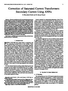
The CT consists of the following: a metallic hollow cylinder (Fig. 1) made as two coaxial ring elements 1, 2 with diametrical jumpers 3, 4, in which body gaps δ1 are made at diagonally opposite ends and ring elements 1 and 2 are electrically isolated from each other by the dielectric 5 and placed secularly. The ferromagnetic closed core 6 with test winding 7 is located on diametrical jumpers 3 and 4 and placed on the edges of cylinder of collector outputs 8. The CT operates in the following way. The CT passes the controlled current through the chain of collector outputs 8. The test winding 7 is connected to tester. The maximum current of the transformation range is installed in the controlled chain. The turning metallic hollow cylinder in the scale range of the tester is defined as the necessary value of the of the output signal. The position of the hollow cylinder is fixed using a clamp bolt (not shown in Fig. 1). In the developed CT, the direction of the currents in diametrical jumpers 3 and 4 are mutually antithetic. Thus, the magnetic flux in the ferromagnetic closed core 6 is created by the difference between the currents in these jumpers. Since the turning of the hollow cylinder leads to proportional changes in the length of arcs of the segments of ring elements 1 and 2, the value of the currents in the jumpers is also changed proportionally to the angle. During the transformation of small currents, the bus with current is connected to the clips of diametrical jumpers. In this case, all transformed current passes by diametrical jumpers in one direction due to the presence of gaps δ1 in both hollow cylinders. Thus, the sensitivity threshold of the developed CT during the transformation of small currents decreases to the value of the sensitivity threshold of a simple single-bus CT with a ferromagnetic closed core. Let us define the dependences of the currents ∆ I˙T = I˙1' + I˙1'' from the transformed primary current I˙1 . For this purpose, for each ring element, we will show the current path I˙'1 and I˙''1 and write the following
119
120
AMIROV et al. (a) 1 2
8
(b) 5
I 4
1
(a) 2
5
'I1
3
I1
R2(α)
RΤ R2(α)
''I1
'I1
R1(α)
α
4
I
7
8
6
180° – α
8
Fig. 2. Direction of the currents in the first (a) and second (b) ring elements.
7 1, 2
2 I1 3, 4
A–A
2R1(α)
1
3
4
.
I1 1 2R2(α)
RΤ
Fig. 3. Equivalent circuit of the substitution of CT.
8
∆ IΤ' 100
5
80
A
α=0
60
I2
α = 30° α = 45° α = 60°
40
δ2 5
2
.
I1''
.
8
2
RΤ
.
6 6
.
I1'
I1
δ1
I2
1
r
'I1
'I1 RΤ
RΤ
8
α'
I1 R (α) 1
(c)
8
(b)
180° – α
Φ
I2
3 I1 7 6
8
20
I1 8
A
0
20
40
60
.
80
100 I1'
Fig. 1. Multiband current transformer: (a) axonometric drawing; (b) laboratory mock-up; (c) front, top and sectional A–A views with collector outputs.
Fig. 4. Dependence of the different current ∆ I˙T on the
expressions for electrical resistance of the sections (Fig. 2):
where ρ, S are the resistivity of the material and the area of the cross section of the ring elements, respectively, and RΤ is the electrical resistance of diametrical jumper. The electrical circuit of the substitution of the ring elements is presented in Fig. 3.
πr ----------- ( 180° – α ) l1 ( α ) 180° R 1 ( α ) = ρ ------------ = ρ --------------------------------------; S S πr -----------α l2 ( α ) 180° R 2 ( α ) = ρ ------------ = ρ ---------------- ; S S l 2r R T ( α ) = ρ ---T- = ρ -----, S S
transformed current I˙1 at different values of α.
According to this circuit, 2R 2 ( α ) + R T U˙ 12 - I˙1 ; I '1 = ------------------------------ = -------------------------------------------------------2 [ R1 ( α ) + R2 ( α ) + RT ] 2R 1 ( α ) + R T 2R 1 ( α ) + R T U˙ 12 - I˙1 . I ''1 = ------------------------------ = -------------------------------------------------------2 [ R1 ( α ) + R2 ( α ) + RT ] 2R 1 ( α ) + R T RUSSIAN ELECTRICAL ENGINEERING
Vol. 80
No. 2
2009
MULTIBAND CURRENT TRANSFORMERS
With the use of I˙'1 and I˙''1 , we will define the expression of the difference current in diametrical jumpers as follows: R2 ( α ) – R1 ( α ) ˙ ∆I˙;T = I˙'1 – I˙1'' = ------------------------------------------------I 1 R1 ( α ) + R2 ( α ) + RT πr --------α – πr 90° = ------------------------- I˙1 = r(2 + π)
The expression ∆ I˙T = f( I˙1 ) shows that the difference current depends on the rotation angle of the ring elements relative to the bus with the transformed current I˙1 . The dependences ∆ I˙T = f( I˙1 ) at different values of α are presented in Fig. 4. This is evidence that, as angle α approaches 90°, the difference current ∆ I˙T significantly decreases, consequently preventing the saturation of the closed core material during the transformation of heavy currents. Thus, the developed multiband CT allows one to transform the currents in the very wide range.
Vol. 80
ACKNOWLEDGMENTS This work was conducted at the Tashkent Institute of Railway Transport Engineers. Contact telephone number (+99871) 299-04-44, 299-07-84. REFERENCES
π --------α – π 90° ---------------------- . 2+π
RUSSIAN ELECTRICAL ENGINEERING
121
No. 2
1. Afanas’ev, Yu.V., etc., Transformatory toka (Current transformers), Moscow: Energoatomizdat, 1989. 2. Markvardt, K.G., Elektrosnabzhenie elektrifitsirovannykh zheleznykh dorog (Power supply of electrified railways), Moscow: Transport, 1982. 3. Semenko, N.G., Gamazov, Yu.A., Izmeritel’nye preobrazovateli bol’shykh elektricheskikh tokov i ikh metrologicheskoe obespechenie (Measuring Transformers of Heavy Electric Currents and Their Metrological Assurance), Moscow: Izd. Standartov, 1984. 4. Amirov, S.F., Khushbokov, B.Kh., Balgaev, N.E., The Problems of the Expansion of the Top Range of Measurements of Current Transformers // Trudy nauchnotekhnicheskoi konferentsii «Resursosberegayushie tekhnologii na zheleznodorozhnom transporte» (Proc. of Scientific and Technical Conference “Resource-Saving Technologies on Railway Transport”), 2006, pp. 43–44.
2009