Abstract. The multibunch collision by means of pretzel scheme to en- hance the luminosity in BEPC have been studied. The mod- ification of the lattice is carried ...
MULTIBUNCH COLLISION SCHEME IN BEPC L.F.Wang, C.Zhang, Z.Y.Guo and S.H.Wang Institute of High Energy Physics Chinese Academy of Sciences, P.O. Box 918, Beijing, P.R.China Abstract
¤ ¤
The multibunch collision by means of pretzel scheme to enhance the luminosity in BEPC have been studied. The modification of the lattice is carried out, the solenoid compensation and chromaticity correction are studied, the physical aperture is examined, the long range beam-beam interaction and coupled bunch instabilities are investigated. The results show that the pretzel scheme with six bunches per beam is feasible.
¤
Table 1 The parameters of multibunch collision in BEPC
Betatron tune Natural emittance Bunch number per beam Natural Bunch length Bunch current Luminosity
2.0 1.2 0.05 5.84 6.76 3.23×10⁻⁷ 6 5 25.3 5.5×1031
Electron
¤
¤
¤
SIP
¤
¤
¤
¤ ¤
¤
¤
¤
Positron
¤
Electron
¤
¤
¤
¤
SIP
¤
¤
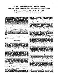
Figure 2: Pretzel orbits of Collision Mode
2
SOLENOID COMPENSATION
Global correction for detector solenoid field with skew quadrupole applied in BEPC now is not suitable for the pretzel scheme. The skew quadrupole where electron and positron beams have no-zero horizontal pretzel orbits of opposite sign can produce vertical orbit separation with opposite sign for two beams. Furthermore, the vertical orbits yc± in the sextupole then give rise to an equivalent skew quadrupole components of opposite sign for the two beams: (k˜1 )ef f = k2 yc± ,
The superperiodicity number of pretzel scheme lattice is one with mirror symmetry in comparison with the superperiodicity number of two in the present lattice. Additional twenty quadrupole and fourteen sextupole power supplies are required.
0-7803-4376-X/98/$10.00 1998 IEEE
Positron
Figure 1: Pretzel orbit of injection mode
The purpose of pretzel scheme is to enhance luminosity by increasing the number of bunches Nb beyond the present Nb =1. Since Nb evenly spaced bunches encounter each other in 2 Nb points around the ring and collision is desired only at the south interaction point (IP) in BEPC. Multibunch collision can give rise to unwanted destructive beambeam interactions at parasitic encounters unless something can be done to separate the beams there. As the operating betatron tunes are νx =5.84 and νy =6.76, six bunches are allowed with the pretzel, which is generated in horizontal direction by three separators. Two separators are placed on each side of south IP, and the third one is placed at the north IP. Only one separator, i.e. the north one is used when beams are injected to generate the pretzel orbits, (see Figure 1). As shown in Figure 2, three separators are applied when two beams are brought onto collision. The main parameters of multibunch collision scheme are list in Table 1. The results presented in the following sections are based on these data.
E(GeV) β x (m) β y (m) νx νy ε0 (rad·m) Nb σl (cm) Ib (mA) L(cm−2 s−1 )
¤
¤
1 LATTICE MODIFICATION
Energy Betatron function at IP
¤
(1)
where k2 is the sextupole strength. The different equivalent skew quadrupole components will make two beam have different coupling, so the simultaneous coupling compensation for both beams gets difficult. The rotating frame method is adopted in our pretzel scheme. Two quadrupoles on each side of south IP are rotated by 3.0825◦, following by one compensator solenoid. The coupling is compensated locally in the interaction region where is no pretzel orbit. Figure 3 gives vertical orbit and vertical dispersion function along the ring. It can be seen from Figure 3 that the
1828
vertical orbit and vertical dispersion function are negligible.
Y/σy
150 · ·
··
Tracking 1000 turns · dp/p= 0.000 ◊ dp/p=+0.008 ¤ dp/p=-0.008
·
·
100 y
08/05/97 20.35.53
.0030
Dy .0025
.0100
·
Dy (m)
y (m) [*10**( -3)]
.0125
·
Positron,Collision mode BEPC Pretzel Collision Mode with Local Bes Solenoid Compensation HP/UX version 8.20/4
.0075
··
50
.0015
·
· ¤
·
.0010
·
◊◊ ◊¤ ◊¤ ◊¤ ¤¤¤ ¤◊◊ ◊◊
·
.0005
·· 0.0
0.0
· · ·
-.0005
-.0025
0
-.0010 -.0050
·
-40
¤
¤
¤ ·· ¤
¤
·
.0050 .0025
¤ ¤ ¤· ¤ ·
¤
.0020
◊◊
◊◊
◊◊ ◊◊
◊
· · ¤ · ¤ ¤· ¤ ¤· ¤·
◊◊◊◊◊◊ ◊
◊ ¤◊ ¤ ◊◊¤¤¤
-20
0
¤ · ◊
·
·
· ◊ ◊ ◊· ◊ ¤ ¤ · ◊◊ ¤¤ ¤ ·
20
40
-.0015
X/σx
-.0075 -.0020 -.0100
-.0025
-.0125
Figure 5: Dynamic aperture of positron
-.0030 0.0
25.
δ E/ p 0 c
=
50.
75.
100.
125.
150.
175.
200.
225.
250. s (m)
0.
Table name = TWISS
150 ·· ·
100
3 CHROMATICITY CORRECTION
·
···
50
·
·
0
(2)
¤
·
·
··
·
-40
¤◊ ¤◊ ¤◊ ¤ ◊
¤ ¤
¤
¤ ¤ · ·· ¤ · · ¤ ¤¤ ¤ ¤ ¤· · ·· · ◊◊◊◊ ◊◊◊ ◊· ◊ ◊¤ ¤ ¤· ◊ ¤ ¤ ◊ ·
¤
·
◊◊◊ ◊◊¤¤¤ ◊◊ ¤◊ ¤¤
◊◊◊
◊ ◊◊◊◊
◊◊◊
¤¤ ◊
-20
0
·
20
40
Figure 6: Dynamic aperture of electron
Outside (mm)
here, xc is the horizontal pretzel orbit. The investigation shows that there are enough vertical physical aperture for both electron and positron beams. Figure 7 and Figure 8 display the horizontal physical aperture of positron and electron beams respectively. It can be seen from these figures that the positron beam has enough horizontal physical aperture, but it is not satisfied for electron beam in the injection region, which needs to be improved.
Coupling=0.2
100
0
Inside
LMS
LMS
-100
2νy
νx+νy
2νx
50
100
150
200 S (m)
3νx
νx+2νy
νx-2νy
0
Figure 7: Horizontal physical aperture of positron beam
4νx
2νx+2νy
2νx-2νy
¤
·
νy
νx νx-νy
νx = 0.1641 νy = 0.2393
4νy
·
X/σx
2000
1500
·
·
·
where x± c are the horizontal orbits of two beams. The equivalent quadrupoles will disturb the betatron motion, the betatron function, betatron tune and other parameters get different for two beams. As there is only one interaction point with head-on collision in the pretzel scheme, this leads to the conditions for a symmetric pretzel scheme (see figure 1 and 2) in which the effects of sextupole perturbation do not cancel. All sextupoles are adjusted to make betatron tune, chromaticity and betatron function at south IP independent of pretzel amplitude (and therefore the same for electron and positron). Eighteen independent sextupoles are needed in the pretzel scheme. Code PCCC(pretzel chromaticity correction code)[2] will be used to compensate the chromaticity. PCCC code also gives the analysis of the resonance excited by sextupoles. Figure 4 shows the particle tracking spectrum given by PCCC. Figure 5 and 6 show the dynamic aperture of positron and electron beams respectively.
·
¤¤¤
Pretzel orbits pass off-center horizontally in sextupoles, and then an effective normal quadrupole of opposite sign for two beams is generated: (k1 )ef f = k2 x± c
Tracking 1000 turns · dp/p= 0.000 · ◊ dp/p=+0.008 · · ¤ dp/p=-0.008
·
Y/σy
Figure 3: vertical orbit and dispersion function
1000
500
5 0
0
0.1
0.2
0.3
0.4
LONG RANGE BEAM-BEAM INTERACTION
The strength of the parasitic beam-beam effects are characterized by the equivalent linear tune shift
0.5
νx
Figure 4: tracking FFT spectrum N βx re ξx = 2πγ
4 PHYSICAL APERTURE
Z 0
∞
dt(1 −
2X 2 ) 2σx2 + t
The beam stay clear region in pretzel scheme is defined as:
exp(−X 2 /(2σx2 + t) − Y 2 /(2σy2 + t))
BSCx =xc ±10σx ±10mm BSCy =±10σy ±5mm
(2σx2 + t)3/2 (2σy2 + t)1/2
1829
,
(3)
Outside (mm)
6 COUPLED BUNCH INSTABILITIES The transverse growth time due to HOMs[3] is estimated as 2.0 second which is longer than transverse radiation damping time 22 ms, the longitudinal growth time due to HOMs[3] is as 0.20 ms, which is shorter than the its radiation damping time of 11 ms. As the two beams are stored in the same vacuum chamber in BEPC, the wake field excited by one beam will dis˜ turb the motion of another beam. The shunt impedance R seen by the counter-moving bunches becomes complex in the general case. For a symmetric cavity,
Coupling=0.2
100
0
Inside
LMS
LMS
-100
0
50
100
150
200 S (m)
Figure 8: Horizontal physical aperture of electron beam where X and Y are horizontal and vertical separations respectively. The formula for ξ y is similar. Figure 9 gives the parasitic beam-beam parameters versus horizontal separation calculated with eq.(3). The Figure 9 indicates that the horizontal parasitic beam-beam parameter is negative when horizontal separation is larger than about σx . The parasitic beam-beam parameters of collision mode in the parasitic IPs are given in Table 2.
˜ = ±R, R
(5)
where R is the shunt impedance seen by the co-moving bunches, the “+” (“-”) sign applies to the symmetric (antisymmetric) mode. The longitudinal growth time is calculated as 0.11 ms when the counter-moving bunches is considered[2]. Figure 10 gives the transverse growth rate versus transverse tune due to resistive wall effect. Therefore the feedback system is needed for pretzel scheme.
0.06 125
0.04
1/τ (1/sec)
100
0.02
ξx
ξy
75
50
0.00 25
-0.02
0
2
4
6
8
0
10
5
5.2
5.4
5.6
X/σx
5.8
6
νx
Figure 9: parasitic beam-beam parameters vs. separation
Figure 10: transverse resistive wall growth rate vs. tune
Table 2 : Long range b-b parameter of collision mode P j P j X(mm) X/σx |ξ x j | ξy j ξx ξν min min max max
7 SUMMARY
15.0
10.4
3.92×10⁻⁴
8.95 ×10⁻⁴
-0.0018
0.0017
In each parasitic interaction point, the bunches receive a kick. In the case of X¿¿σx , the beam-beam kick can be expressed as
The pretzel scheme is one of the feasible methods for BEPC to increase the luminosity. The solenoid can be locally compensated. The chromaticity can be compensated by adding more independent sextupole power supplies. The long range beam-beam effect is tolerable. However, the longitudinal coupled bunch instability may limit the multibunch performance and feedback system is needed.
2N re , (4) γX where N is the bunch population, re is the classical electron radius and γ is the relativistic energy. The closed orbit distortion at south IP caused by all parasitic beam-beam kicks is calculated as 0.25 mm which is about half of the horizontal beam size. This current dependent horizontal orbit at IP should be adjusted during collision. The long range beam-beam interaction will reduce the stable tune space and cause betatron tune split. In the case of horizontal separation, the injection on the horizontal plane will make a larger tune spread due to long range beam-beam interaction, and therefore vertical injection is preferred. x0 = −
1830
8
REFERENCES
1. H. Grote and F. .C Iselin, CERN/SL/90-13(AP), 1996. 2. F.L.Wang, Ph.D. thesis, 1997. 3. J.Qin, Private communication.