Multicast in 3G Networks: Employment of Existing IP Multicast Protocols in UMTS Mariann Hauge
Øyvind Kure
Center for Technology at Kjeller P.O. Box 70, N-2027 Kjeller, Norway +47 95937888
Center for Technology at Kjeller P.O. Box 70, N-2027 Kjeller, Norway +47 64844736
[email protected]
[email protected]
tages are bandwidth savings over thinner links, and reduced resource consumptions in servers. In UMTS bandwidth is a limiting resource, in all cell environments the available radio resources can support only a handful high data-rate user simultaneously. UMTS is therefore likely to have an interface to multicast.
ABSTRACT In this article we discuss the use of commonly deployed IP multicast protocols in UMTS networks. We analyze three possible UMTS multicast architectures, all employing standard IP multicast protocols. We study the architectures’ ability to handle: group management, data-security, authentication and authorization of multicast source/receivers, multicast session identification, terminal mobility and collection of billing data. For one of the architectures we quantify the performance of the design for two multimedia service examples.
Some of the existing Internet services are provided by multicast distribution. Clearly a UMTS terminal must therefore be able to participate in a multicast session. The open questions lies in the choice of UMTS multicast architecture. To what extent shall multicast be supported in the network? How much of the UMTS network must be multicast aware? Should the currently available IP multicast protocols be used, or should new protocols, adapted to special UMTS needs, be developed?
Categories and Subject Descriptors C.2.1 [Computer-Communication Networks]: Network Architecture and Design – wireless communication, packet-switching networks.
In this paper we present an analysis of IP multicast protocol architectures in UMTS. Reuse of IP multicast protocols in UMTS eliminates the need for application gateways, and reduces the time and cost for development of new protocols. This was the motivation behind the study. UMTS is being standardized in several stages, so its capabilities are therefore still being developed and enhanced. An analysis of the strength and weakness of the Internet multicast architecture in UMTS is therefore of value.
General Terms Algorithms, Performance, Security, Standardization.
Keywords multicast, UMTS, wireless internet, IGMP, SSM.
Three potential Internet multicast architectures will be analyzed. The first is the existing multicast architecture that is standardized as an optional feature in the UMTS network. In this architecture the IP multicast routing protocol is terminated in the gateway between the Internet and the UMTS network. This solution requires few multicast aware UMTS nodes. However, this architecture does no provide any bandwidth savings in the UMTS network. The two other designs are Internet multicast architectures where the multicast functionality is pushed successively further out towards the UMTS terminal. These two architectures require multicast awareness from an increased number of UMTS network nodes. Higher complexity is introduced to achieve network resource savings.
1. INTRODUCTION UMTS is a family of third generation mobile networks designed to offer high bandwidth radio access. It can provide maximum data-rates ranging from 64kb/s - 2Mb/s in different environment types. UMTS is designed to provide access to the existing Internet services as well as UMTS specific services. It will augment the existing capabilities of 2G mobile networks and GPRS, and one often envisaged strategy is to offer a richer set of multimedia services. Multicast is one alternative delivery method for streaming media. It has been used for videoconferences, and it is gaining momentum for radio and video streaming, and game playing. Its advan-
We will focus our discussion on the chosen architecture’s ability to handle the following significant multicast issues: Multicast group management, data privacy and integrity, traffic charging mechanisms, sender and receiver mobility handling and minimized network resource consumption. These issues will be explained in more detail further on in the paper.
Permission to make digital or hard copies of all or part of this work for personal or classroom use is granted without fee provided that copies are not made or distributed for profit or commercial advantage and that copies bear this notice and the full citation on the first page. To copy otherwise, or republish, to post on servers or to redistribute to lists, requires prior specific permission and/or a fee. WoWMoM’02, September 28, 2002, Atlanta, Georgia, USA. Copyright 2002 ACM 1-58113-474-6/02/0009…$5.00.
In the ensuing section we will summarize related work, next we give an overview of the UMTS network model used in the following discussion. We continue by presenting our analysis of IP multicast in UMTS. Finally we conclude the paper.
1
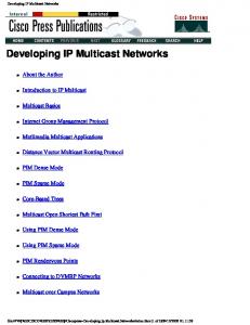
The GGSN (Gateway GPRS Support Node) is the translator (gateway) between external networks (ex. the Internet) and UMTS, while the RNC can be thought of as an internal translator (gateway) between the UMTS Core Network and UTRAN. Subscription and equipment administration is aided by the Home Location Register (HLR), Authentication Centre (AuC), Equipment Identity Register (EIR), and the Charging Gateway Function (CGF).
2. RELATED WORK One of the multicast architectures presented later on in this article is included in the UMTS standards provided by the UMTS standardizing body 3GPP[2]. This design uses IP multicast protocols. The solution is simple to implement, but does not reduce network resource consumption. 3GPP are currently in the process of defining a new multicast/broadcast architecture[1]. Preliminary requirements for this design indicates that it will consist of proprietary protocols appended to the Internet protocols via application gateways. Multicast support will be introduced both in the UMTS Core Network and in the UMTS Radio Network. In contrast to 3GPPs current position, we want to study possible deployments of the existing IP multicast protocols. Such multicast architectures eliminates the need for application gateways, and reduces the time and cost for development of new protocols.
All radio architecture specific controls are located in UTRAN. UTRAN also handles mobility (handover/relocation) of active terminals. The Core Network is not involved except when a handover between RNCs or SGSNs are needed. The interface between the Core Network and UTRAN is fully specified in 3GPP’s standards[19]. The Core Network manages the UMTS terminals. It handles location updates for inactive terminals, terminal authentication, service authorization, and holds subscription information for the terminals.
A number of architectures have been proposed that aims to reduce the signaling overhead and distribution latency for mobile multicast receivers. Some of these are extensions to Mobile IP (ex. [15] and [6]). Others are protocols meant for Wireless LAN or UMTS environments [18] and [16]. These protocols use a layered architecture, mobility prediction or a combination of both to support mobility. We have chosen to use the existing soft handover mechanisms in UMTS as mobility prediction. This allows us to perform a new multicast registration on the multicast routing tree prior to the actual handover.
When UMTS terminals want to send or receive IP data traffic, the following procedures are required: The terminal must have made itself known to the UMTS packet-data network (performed a “GPRS attach”). During the GPRS attach, the UMTS terminal is authenticated by the SGSN (Serving GPRS Support Node) in the Core Network and a key for optional data encryption on the radio access network (UTRAN) is established. The SGSN verifies that the authenticated terminal holds a subscription that allows packetdata traffic.
3. UMTS ARCHITECTURE OVERVIEW
Next, a packet switched data channel must be established between the UMTS terminal and the GGSN (PDP context activation). During this process the SGSN also checks the subscription information to fetch traffic charging specifications and instructions for address assignment.
A successful deployment of the Internet multicast architecture in UMTS relays on efficient use of existing mechanisms in the UMTS network. The GPRS (General Packet Radio Service) platform designed for packet-data traffic in UMTS is used for unicast end-to-end IP traffic. It is essential to use this platform also for IP multicast traffic.
Finally a packet-data protocol address must be assigned to the terminal. In the IP case, an IP address can be assigned to the UMTS terminal in four different ways: 1. A static IP address is reserved for the terminal. This address is obtained from the range of IP addresses assigned to the Internet Service Provider (ISP)/GGSN in the terminal’s home network. IP traffic destined to the terminal will arrive at the terminal’s home GGSN. Next the packets will be forwarded on the terminal’s packet-data channel, or they must be tunneled through the UMTS Core Network to the PLMN where the terminal is currently roaming/visiting1. 2. A dynamic IP address is given to the terminal from the home network. The terminal will be assigned an available address from the home ISP/GGSN’s dynamic address pool. The IP address associated with the UMTS terminal will differ between packetdata sessions. IP traffic routing will be identical to the static address case presented above.
Figure 1: The GPRS platform In this section we give a short introduction to the GPRS platform in UMTS. The network representation illustrated in Figure 1 will serve as the network reference for the discussion in the rest of the paper. The network is divided in two parts, the UMTS Core Network and the UMTS Terrestrial Radio Access Network (UTRAN). UTRAN is subsequently divided in Radio Network Subsystems (RNS). Each RNS consist of one Radio Network Controller (RNC) and a number of base stations (Node-B). A complete UMTS network is called Public Land Mobile Network (PLMN).
3. A dynamic IP address is given to the terminal from the pool of dynamic addresses assigned to the ISP/GGSN in the visited 1
2
Roaming means that the UMTS terminal is moving from one UMTS network to another while it has an activated packet-data channel (PDP context). Visiting means that the UMTS terminal starts/activates a new packet-data channel (PDP context) in the visited UMTS network.
Minimized network resource consumption
network. IP traffic from external networks will arrive at the GGSN in the visiting network where the IP address was assigned. If the terminal roams into another network while this packet-data session is still active, IP traffic must be tunneled from the GGSN that provided the IP address to the PLMN where the terminal has moved.
Multicast group management Data privacy and integrity Charging mechanisms Sender and receiver mobility handling
4. A dynamic or static IP address can be provided from an external PDN (Packet Data Network). The IP address can be obtained either by negotiations between the UMTS terminal and the external packet-data network, or between the GGSN (on behalf of the UMTS terminal) and the external packet-data network. Packet-data destined for the UMTS terminal will in this case arrive at the GGSN associated with the specified external network.
A brief description of each topic follows: Minimized network resource consumption: The reason for introducing multicast in UMTS is to minimize consumption of network resources. We will investigate how well the different architectures fulfill this goal. Multicast group management: IGMP[10] is the commonly deployed group management protocol on the Internet. The current version (v2) allows hosts to join and leave multicast groups identified with a Class D IP address. IGMP keeps track of multicast memberships for each subnet. It does not store multicast membership for each host. Detailed membership information for each host is necessary for charging mechanisms and security.
The UMTS network must implement the assignment of IPv4 addresses. Implementation of IPv6 address assignments is optional. In addition to the mentioned IP address assignments, the GGSN is standardized to offer Mobile IP’s Foreign Agent (FA) functionality as an optional feature. There is a charging profile associated with each packet-data channel in UMTS. The GGSN, SGSN, and to a small extent the RNC collect billing data. A charging record is opened in each of these nodes for each packet-data channel. Among other parameters, the charging records can monitor the following elements: connection time, amount of data sent and received, source or range of sources for received data, destination port for the packet-flow, and Quality of Service (QoS) parameters for the packet-data channel.
Internet multicast uses “flat” location independent Class D IP addresses to identify the different multicast sessions. There is no mechanism that oversees that two neighboring multicast sources does not choose the same Class D multicast address for two concurrent multicast sessions. A malicious source can freely transmit data to an ongoing multicast session to perform a Denial Of Service attack (DOS). IETF is discussing different mechanisms for controlled Class D address allocation (ex. MAAA[17]), however none has become successful yet. Another solution to the session identification problem is provided by SSM[11]. This protocol identifies a multicast session by a (S, G) tuple (S = Source IP address, G = Class D multicast address). This scheme supports unique multicast session identification. A new version of IGMP (v3)[5] is under discussion in IETF. This version allows hosts to join and leave multicast traffic from specified sources and is meant to support the (S, G) scheme of SSM. Unique multicast session identification is necessary to avoid DOS, to provide accurate charging, and to simplify the multicast security mechanisms.
This was a brief description of the UMTS characteristics important for the following discussion. For more information consult one of the many textbooks written about the 3G networks (ex. [14]) or read the UMTS standards published by the UMTS standardizing body 3GPP[19].
4. MULTICAST IN UMTS The main advantages associated with multicast are bandwidth savings over thinner links and reduced resource consumptions in servers. Naturally, multicast also has some disadvantages: A set of shortcomings associated with the existing IP multicast protocols are shown in[7]. The authors argue that the mentioned mechanisms must be available in the multicast protocols for the architecture to become successful. The important multicast mechanisms identified in the article include: weak group management, no authorization, no data-flow security and no support for traffic charging. Several of these mechanisms (authentication, authorization, data-flow security and traffic charging) are available for packet switched traffic in the GPRS platform in UMTS.
There is no mechanism in IGMP, or in the multicast routing protocols (PIM-SM or SSM) that performs authentication of multicast members and sources. Member/source authentication is important when the multicast content is classified, or the content is a charged service. A unique multicast session identifier (ex. the (S, G) tuple) will simplify the sender and receiver authentication procedure. Data privacy and Integrity: Several multicast services might want to secure the multicast data-flow such that “wire tapping” of the multicast traffic is useless. For this, a mechanism for key distribution is needed. It is commonly agreed that privacy and integrity mechanism must exist for multicast. An IETF Multicast Security (msec) Working Group[12] is currently working to propose a standard for the security mechanisms.
The aims for this discussion is to incorporate the IP multicast protocols in the UMTS network, associate the architecture with the available UMTS mechanisms and see how well the resulting design performs. We have chosen IGMPv3[5] and PIM-SM[9]/SSM[11] as the set of multicast protocols for this study. We have chosen this protocol-set due to its current popularity among network node manufacturers. Other IP multicast routing protocols (ex. CBT[4] and CSM [3]) might have properties that makes them better suitable for UMTS. An analysis of these and yet other interesting IP multicast protocols’ performance in UMTS, are left for future study.
Charging mechanisms: Most content distribution will be charged based services. The IP multicast protocols do not provide mechanisms for charging. All of the issues described so far are an integral part of a trustworthy charging procedure. Sender and receiver mobility handling: The Internet multicast protocols are designed for static hosts. UMTS terminals will often
We evaluate the architectures based the following list of issues:
3
Furthermore, the multicast architecture requires multicast routing protocol support (ex. PIM-SM, SSM) and IGMP support from the GGSN. This functionality includes identification and replication of multicast data.
move. It must be verified how well the existing IP multicast protocols are able to handle mobile multicast sources and receivers. An Internet multicast architecture is already available in the UMTS standards. We start our analysis by presenting the existing solution.
A limiting factor in the GGSN is the number of concurrent active PDP contexts. Multicast termination in GGSN requires one PDP context dedicated to IGMP signaling for each multicast member. One or more PDP contexts are also required for each multicast member to receive the multicast data. This means that multicast traffic will in many cases require more PDP context resources than unicast distribution of the same data.
4.1 Existing UTMS Multicast Multicast is standardized as an optional feature in the UMTS network[2]. In the current UMTS multicast design, 3GPP has chosen to terminate the IP multicast routing protocol in the gateway between UMTS and the Internet (in GGSN, ref. Figure 1). GGSN also serves as an IGMP designated router and performs IGMP signaling on point-to-point packet-data channels. IGMP signaling is performed in the network user plane (it is seen as data traffic for the UMTS network). Multicast data is forwarded to the UMTS terminal on point-to-point packet-data channels (unicast distribution). Which IP multicast routing protocol to support is the choice of the GGSN manufacturer. Only the UMTS terminal and the GGSN is multicast aware in this design. This architecture allows the network to treat multicast traffic in the same manner as unicast traffic (ex. for admission and congestion control, QoS handling etc.).
In short terms, this multicast architecture enables a UMTS terminal to participate in multicast sessions. The drawback is that it (in most cases) requires more network resources than unicast distribution of the same data. Multicast group management in this architecture is improved for the multicast members residing on the UMTS network. Due to the point-to-point channels used for IGMP signaling, the IGMP process in the GGSN handles each UMTS multicast member at individual “interfaces”. This means that the IGMP process stores multicast information for all group members. Detailed membership information for the UMTS terminals is therefore available to the UMTS network at the IGMP router in the GGSN.
To send/receive multicast data, the terminal must perform a “GPRS attach”. Next the terminal must establish a packet-data channel with the GGSN (PDP context activation). The UMTS terminal is now part of the IGMP environment, and can join and leave multicast groups using normal IGMP signaling. Finally the terminal must establish one or more packet-data channels for the multicast data flows.
Unique multicast session identification can be provided by the (S, G) identifier of SSM and IGMPv3. No UMTS specific mechanisms exist to provide any other unique session identification. Upon the UMTS mechanisms “GPRS attach” and IGMP “PDP context activation”, the UMTS terminal is authenticated by the network and authorized for multicast traffic. If unique multicast service identification exists, this authorization mechanism could be modified to operate on individual multicast sessions. However, there is no mechanism in IGMP to report a multicast service authorization failure to the UMTS terminal.
Multicast data destined to a roaming terminal will be tunneled through the Core network from the GGSN associated with its IP address to the SGSN currently hosting the terminal. Traffic from roaming multicast sources will also be tunneled through the Core Network. In a mobile network with roaming sources and receivers the data distribution will be inefficient.
There is no mechanism available to authorize a sender to transmit to a specific multicast session. The use of SSM’s (S, G) session identifier eliminates this problem. For Internet multicast sources, IPSEC Authentication Header[13] may be used to authenticate the source of an SSM transmission. The use of IPSEC requires a key distribution mechanism.
This multicast architecture reduces the load on a wireless source. The source only needs to send one copy of the multicast data to the GGSN. It will be the GGSN’s job to forward the packet on to the multicast distribution tree. The drawback of this design is that the UMTS multicast source does not receive any information from multicast members. When the multicast group does not have any members, the source continues to transmit its multicast data to the GGSN. The source is not aware of the empty state of the multicast group. A modified signaling connection between the GGSN and the source can avoid this situation.
The UMTS network also provides some support for data privacy and integrity. During the “GPRS attach” each UMTS terminal is provided with a key for encryption. This mechanism ensures that an intruder that is eavesdropping on the network cannot interpret the multicast traffic. This mechanism does not however, stop a UMTS subscriber from receiving the multicast data if he is authorized to receive multicast traffic and can join the relevant multicast group. A separate protocol for key distribution and data encryption performed by the source must be available to limit the group of multicast receivers to the authorized ones.
This architecture also imposes a high strain on the GGSN. The GGSN already has the responsibility for many complex mechanisms, thus it is important to avoid turning the GGSN into the UMTS network’s bottleneck. Some of the GGSN’s standard and optional duties are listed below:
UMTS’s charging mechanisms can be used to some extent for multicast traffic charging. The GGSN replicates incoming multicast packets and forwards this data on a unicast channel for each receiver. The multicast data is treated as unicast data beyond the GGSN replication. Charging records can be placed in the SGSN and GGSN to record multicast charging data in a similar manner as for unicast traffic. As long as there is no unique multicast service identification available, it is not possible to specify a special charging treatment for a certain service. If SSM’s (S, G) identifi-
Packet- and address- translation between external and internal protocols (including tunneling) Map arriving data to correct TFT (traffic flow template) for proper QoS handling. Mobile IP’s Foreign Agent (FA) functionality Acts as DHCP relay agent or client Collect charging data
4
This design eliminates the need for UMTS Core Network tunnels for multicast data reception. The UMTS terminal will always receive the multicast data from the closest GGSN that serves the specified multicast flows.
cation of multicast flows is used, and the (S, G) identifier(s) is set to be constant for a service, it is possible to charge this service separately. Sender and receiver mobility is handled by the existing UMTS mechanisms. The multicast architecture is not aware of any mobility.
Currently no mechanisms exist in the UTMS network to establish a data channel between the RNC and the UMTS terminal, neither are there any mechanisms available to provide data links for the multicast routing tree between the nodes in the Core Network. The GPRS platform must be extended to support such connections.
High network resource consumption and increased load on the GGSN indicates that it might be beneficial to look for other ways to introduce the Internet multicast architectures in UMTS. In the following we present a design where the Internet multicast protocols are pushed further out in the UMTS network.
Multicast termination in RNC allows the UMTS network to apply the existing mechanisms for admission control and congestion control on each flow in the RNC. It also admits the multicast receiver to specify individual QoS parameters for the unicast transport channel between the RNC and the terminal.
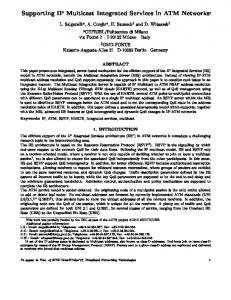
4.2 Multicast Routing Terminated in the RNC The RNC acts as a gateway between the UMTS Core Network and the radio access network (UTRAN) (ref. Figure 1). The RNC is therefore a natural choice for protocol termination/translation. Thus, in this modified multicast architecture we have moved the multicast routing protocol termination from GGSN to RNC. The motivation behind this modification is to minimize network resources consumption in the UMTS Core Network. The resulting multicast architecture is shown in Figure 2.
At first sight it looks like multicast sources should be treated similarly as multicast receivers. The multicast source should unicast its data to the RNC. The RNC would forward the data on to the multicast distribution tree. However, when the multicast source is roaming, it will not have an IP address that belongs to the address range of the visited network. Due to the “valid address check” in multicast routers, multicast packets from a roaming source might be discarded. To avoid packet drops, the multicast routing tree for UMTS sources must be routed via the GGSN associated with the multicast source’s IP address. Additionally, this multicast source strategy imposes many changes to the UMTS network and increases the complexity of roaming agreements between the different network operators. Compared to the multicast source behavior in the existing architecture, the new source treatment is beneficial only when the path between a roaming source and its home GGSN intersects the distribution tree for receivers of these multicast data. We have therefore chosen to let multicast sources unicast the multicast data to their home GGSN, and have the GGSN forward the data on to the multicast distribution tree (this is identical to the source treatment in the existing UMTS multicast).
Figure 2: Multicast routing terminated in RNC. The following description of the multicast architecture contains sufficient details to allow a high-level performance analysis. In this article we don’t intent to provide accurate procedure descriptions required for implementation.
This UMTS multicast architecture distributes most of the multicast processing on the RNCs. A UMTS network has at least an order of magnitude more RNCs than GGSNs. The multicast processing on each RNC is therefore much less than the processing required of the GGSN in the former architecture.
Multicast data will be forwarded using multicast data distribution in the UMTS Core Network and unicast data distribution from the RNC to each UMTS multicast member. The UMTS Core Network nodes forwarding multicast traffic must act as nodes in a multicast routing tree (PIM-SM or SSM). The RNCs will act as leaf-nodes on the multicast tree and terminate the multicast routing protocol. The RNCs also serve as IGMP designated routers and perform IGMP signaling on point-to-point packet-data channels terminated by the UMTS terminal. This design requires a higher multicast awareness in the UMTS network compared to the existing UMTS multicast design.
In short terms, this multicast architecture preserves network resources in the UMTS Core Network and reduces the load on multicast sources. The drawback is that it requires modification of the GPRS platform. Multicast group management is handled in the same way as in the former architecture. Detailed membership information for each UMTS terminal is available to the UMTS network at the IGMP router in the RNC. For accurate up-to-date group information, it is required that the UMTS terminal signals an explicit IGMP leave when it does not want to listen to a multicast group any more. The current version of the IGMP protocol allows a host to leave a group either by explicit signaling, or by time-out.
The terminal learns the UMTS network’s multicast support from broadcasted network information. If the network supports multicast, the terminal can proceed to initiate this service: To send/receive multicast data the terminal must perform a “GPRS attach”, and establish a packet-data channel with the RNC for IGMP signaling. The UMTS terminal is now part of the IGMP environment, and can join and leave multicast groups using normal IGMP signaling. Next, the terminal must establish one or more packet-data channels with the RNC for multicast data flows. Finally, the multicast routing protocol in the RNC must perform the proper multicast signaling to join the correct distribution tree.
Unique multicast session identification can be provided by the (S, G) identifier of SSM and IGMPv3. Source and receiver authentication will be performed during a “GPRS attach”. Upon the establishment of a data channel for
5
The terminal learns the UMTS network’s multicast support from broadcasted network information. If the network supports multicast, the terminal can proceed to initiate this service. To send/receive multicast data the UMTS terminal must perform a “GPRS attach”, and initialize IGMP signaling. The UMTS terminal is now part of the IGMP environment, and can join and leave multicast groups using normal IGMP signaling. Next, the IP multicast routing protocol (PIM-SM or SSM) in the base station must perform the correct multicast routing signaling to join the proper distribution tree. Finally a broadcast channel must be established for broadcast of the multicast data on the radio network.
IGMP signaling, the terminal must be authorized for multicast services. This authorization does not exist in the existing platform and must be included in the RNC - SGSN signaling. UTRAN is protected against eavesdropping, but a separate protocol for key distribution and data encryption performed by the source must be available to limit the group of multicast receivers to the authorized ones. UMTS’s charging mechanisms can be used as in the existing architecture. However, it is necessary to implement a new signaling procedure between the RNC (that stores the up-to-date membership information) and the SGSN to report any change in the multicast memberships for each terminal.
In the previous architecture we concluded that full multicast distribution for UMTS multicast sources was not beneficial. Thus, we keep the multicast source handling from the existing UMTS multicast architecture, where the source unicast its data to the GGSN. GGSN forwards the data onto the multicast routing tree.
The frequent handovers between base stations are handled by the mobility mechanisms in UTRAN. This handover procedure must be modified to handle the new multicast channels, but will stay unchanged otherwise. Handovers between RNCs and between SGSNs are visible also in the Core Network and will affect the multicast routing tree. These handovers are usually infrequent, planned handovers. Modified signaling can inform the new node about multicast memberships prior to the handover.
In short terms, this multicast architecture preserves network resources in the UMTS Core Network and UTRAN, and reduces the load on multicast sources. The drawback is that it imposes major changes on the UMTS network. Currently no mechanisms exist in the UTMS network to provide the broadcast data channel between the base station and the terminals, neither are there any mechanisms available to provide data links for the multicast routing tree in the UMTS network. The GPRS platform must be modified to support these connections. This architecture also require that some functionality that is currently performed in the RNC only, must now also be available for the broadcast channel in the base station.
This multicast architecture reduces the bandwidth demand in the UMTS Core Network. Unfortunately, the bandwidth-limited links are located in UTRAN. Therefore we will in the following present an architecture where the Internet multicast protocols are pushed even further out in the UMTS network.
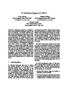
4.3 Multicast throughout the UMTS Network In this architecture, multicast is terminated in the base station (Node-B). The motivation behind this design is to reduce network resource consumption in UTRAN. The resulting multicast architecture is shown in Figure 3.
Multicast group management for this architecture is handled in the same way as in the former architecture. Detailed membership information for the UMTS terminals is available to the UMTS network at the IGMP router in the base station. Explicit IGMP leave signaling is required. Unique multicast session identification is identical to the former architecture. For sender and receiver authentication and authorization, mechanisms must be provided to authorize the terminal for multicast traffic during the IGMP signaling initialization. Otherwise this issue is treated similarly to the previous cases. As in the former architectures, a separate protocol for key distribution and data encryption performed by the source must be available to limit the group of multicast receivers to an authorized set.
Figure 3: Multicast terminated in Node-B This architecture is described in the same manner as the previous architecture; with an equivalent level of detail that allow for a high-level performance analysis.
UMTS’s charging mechanisms can be used as in the previous architecture. However, it is necessary to implement a new signaling procedure between the base station (that stores the up-to-date membership information) and the SGSN to report any change in the multicast memberships for each terminal.
Multicast data is forwarded using multicast data distribution both in the UMTS Core Network and in UTRAN. Unicast channels between the terminal and the base station will be used for IGMP signaling. The UMTS network nodes forwarding multicast traffic must act as nodes in a multicast routing tree. The base stations will act as leaf-nodes on the multicast tree and terminate the multicast routing protocol. The base stations also serve as IGMP designated routers and perform IGMP signaling on point-to-point channels terminated by the UMTS multicast members. This architecture requires that all forwarding nodes in the UMTS network are multicast aware.
The existing UMTS mechanisms for admission control and congestion control are located in the RNC and cannot be used in this architecture. All terminal mobility will be visible for the multicast routing tree. Most handovers in UMTS will be soft handovers. This means that both the old and the new base station will be in contact with the terminal during the handover. This allows the new base station to join the specified multicast sessions prior to the actual handover. However, major modifications must be conducted on the UMTS
6
network to support this multicast architecture. The signaling overhead for the multicast protocols will be noticeable.
Table 1 shows how the two different overhead sources influence the operating cost for different services (handover each 150 seconds). High bit-rate services are punished mainly by the network traffic resulting from the IGMP leave delay during handovers, while low bit-rate services are influenced mainly by the constant signaling needed to maintain the multicast distribution trees. A higher density of service subscribers would reduce the overhead for the high bit-rate service substantially, while it would influence the low bit-rate service to a smaller degree.
A rough estimate of the operating cost in UTRAN for this multicast architecture confirms the expected association between cost and mobility (handover rate). The other necessary calculation is the comparison between the multicast cost induced by high mobility and the resources gained by multicast routing? Next we present the results of these two rough estimates. We chose the following two service types for our calculations:
With the presented overhead and a handover rate of 150 seconds, Figure 5 shows UTRAN data traffic for multicast data distribution. The network traffic is presented as a function of the service subscriber densities. The multicast data traffic is normalized to unicast distribution of the same services. The diagram shows that multicast can potentially reduce UTRAN data traffic significantly for popular services, however multicast will radically increase the data traffic in UTRAN for less popular services. Only major events/services are likely to have a popularity of more than 10%, most services will have significantly fewer receivers.
Watching a live sports event (256kbit/s). Receiving 5 minutes news summary eight times a day (audio and picture presentation at 20kb/s). The bit-rate for the different services is chosen from a study of acceptable media qualities presented in[8]. These bit-rates are optimized for small handheld mobile device. We have chosen a city-centre environment (small radio cells) for the study, and we assume the service receivers are walking in the city. Approximately 10 users are attached to the data network in each cell and we set the service subscription density to 5%. The service subscribers are spread in the network according to the Poisson distribution. We have chosen the default configuration of SSM and IGMPv3 as the multicast protocols for these examples. We assume the UMTS handover mechanism assures that an IGMP leave message is sent to the old base station after a handover. The explicit leave message assures that unnecessary multicast data will be forwarded to the old cell in less than 3 seconds after “leave” is sent. Figure 4 shows the percentage of multicast overhead traffic in UTRAN as a function of handover frequency.
Figure 5: Network traffic from multicast distribution compared to unicast distribution It must be noted that our calculations are based on IGMP and SSM’s network traffic only. We have not included the signaling cost multicast imposes on UTRAN during handovers, nor memory and processor requirements. Addition of this cost will shift the multicast distribution curves on Figure 5 rightwards.
Figure 4: Operating cost for multicast in UTRAN
This multicast architecture provides multicast distribution for the bandwidth limited links in the UMTS network, and might save limited resources. Unfortunately the architecture requires major changes in the UMTS network. We have seen that the mobility handling imposes some overhead on this multicast architecture. Furthermore, broadcast channels will always require worst-case power control and are therefore less efficient than unicast radio channels. Multicast distribution is therefore only beneficial when there are more than a minimum number of multicast receivers in the same cell. We will not address the challenge to find this minimum number in this paper, but rather leave it as an open issue for future study.
The overhead presented in the diagram consists of the SSM and IGMP signaling messages needed to maintain the multicast distribution tree in UTRAN. This signaling traffic is averaged over the connection time to provide a bit/s channel. Forwarding of unnecessary multicast data to the old cell after a handover is also included in the overhead numbers. The total traffic from these two overhead sources are then compared to the average data traffic required by the specific multicast service to provide the Overhead %. Table 1: Multicast overhead in UTRAN (handover each 150s) Service bandwidth Multicast signaling overhead Overhead from IGMP leave delay Overhead %
Sports event 256kb/s 22 bit/s 3180bit/s 1,2%
New update 0,56kb/s 22 bit/s 7 bit/s 5,1%
5. CONCLUSION We have shown three different ways to incorporate existing IP multicast protocols in a UMTS network. The first architecture is included as an optional feature in the current UMTS standards. In this architecture multicast routing is terminated in GGSN. This
7
solution requires minimal changes to the existing packet data network. It is able to use most of the existing UMTS mechanisms for charging, mobility, flow control, etc. This architecture does not utilize multicast’s ability to save network resources. On the contrary, this solution is a greedy user of limited PDP context resources in the GGSN. Multicast distribution requires slightly more network bandwidth compared to unicast distribution of the same data. Obviously this cannot become a permanent multicast solution in UMTS. Multicast is intended to save network resources, not consume extra resources.
[5] B. Cain, et al., “Internet Group Management Protocol, Version 3”, draft-ietf-idmr-igmp-v3-07.txt, March 2001.
[6] W. Chikarmane et al., “Multicast support for mobile hosts using Mobile IP”, Mobile Networks and Applications, 3(4):365-379, 1998.
[7] C. Diot et al., “Deployment Issues for IP Multicast Service and Architecture”, IEEE Network, 14(1):78-89, 2000.
[8] E. Ekudden et al., “On-demand mobile media”, Ericsson Review, 78(4):168-177, 2001.
The second architecture terminates multicast routing in the RNC. This solution requires moderate modifications to the UMTS packed-data network. It is able to use modified versions of most of the existing UMTS mechanisms for mobility, charging etc. This architecture reduces the use of PDP context resources in the GGSN, it also minimizes the need for Core Network resources.
[9] B. Fenner, et al., “Protocol Independent Multicast - Sparse Mode”, draft-ietf-pim-sm-v2-new-03.txt, July 2001.
[10] W. Fenner, “Internet Group Management Protocol, Version 2”, RFC 2236, November 1997.
[11] H. Holbrook and B. Cain, “Source-Specific Multicast for
The last architecture terminates multicast routing in the base station. This solution requires substantial modifications to the packet-data platform. It is not able to make much use of the existing UMTS mechanisms. All terminal mobility is visible for the multicast routing tree and this penalizes the architecture. A multicast architecture in UTRAN can be beneficial for very popular services, but is best provided with proprietary protocols.
IP”, draft-holbrook-ssm-arch-02.txt, March 2001.
[12] IETF Multicast Security working group information at: http://www.ietf.org/html.charters/msec-charter.html
[13] S. Kent and R. Atkinson, “IP Authentication Header”, RFC 2402, November 1998.
[14] J. Korhonen, Introduction to 3G mobile communications,
The second architecture can be interesting for network providers that do not expect to carry much data traffic with very high subscription density. Such traffic will not benefit from multicast support in UTRAN. A detailed study of this solution can be of value.
Artech House, 2001.
[15] C. R. Lin et al., “Mobile Multicast Support in IP Network”, IEICE Transactions on Communications, E84-B(2):245-254, 2001.
6. REFERENCES
[16] C. Tan et al., “MobiCast: A multicast scheme for wireless networks”, Mobile Networks and Applications, 5(4):259-271, 2000.
[1] 3GPP, “TS 22.146: Multimedia Broadcast/Multicast Service, Stage 1”, V6.0.0, 2002.
[17] D. Thaler, et al., “The Internet Multicast Address Allocation
[2] 3GPP, “TS 29.061: Interworking between the Public Land
Architecture”, RFC 2908, September 2000.
Mobile Network (PLMN)”, V5.0.0, 2001.
[18] C. Tseng et al., “A new locality-based IP multicast scheme
[3] S. Aggarwal, et al., “A Flexible Multicast Routing Protocol
for mobile hosts”, Computer Communications, 24(5-6):486495, 2001.
for Group Communication,” Computer Networks, 21(1):3560, 2000.
[19] All UMTS standards are available at: www.3GPP.com
[4] A. Ballardie, “Core Based Trees (CBT version 2) Multicast Routing,” RFC 2189, 1997
8


![[PDF] Download IP Multicast, Volume I: Cisco IP Multicast Networking ...](https://m.moam.info/img/260x300/pdf-download-ip-multicast-volume-i-cisco-ip-multic_647746c2097c474c228bd91e.jpg)


![[PDF] Download IP Multicast, Volume I: Cisco IP Multicast Networking ...](https://m.moam.info/img/260x300/pdf-download-ip-multicast-volume-i-cisco-ip-multic_6477b619097c474d228c582a.jpg)

