International Journal on Advances in Internet Technology, vol 7 no 1 & 2, year 2014, http://www.iariajournals.org/internet_technology/
148
Multicast Source Mobility Support for Regenerative Satellite Networks Esua Kinyuy Jaff, Prashant Pillai, and Yim Fun Hu School of Engineering & Informatics, University of Bradford, Bradford, United Kingdom
[email protected],
[email protected],
[email protected] Abstract — Satellite communications provides an effective solution to the ever increasing demand for mobile and ubiquitous communications especially in areas where terrestrial communication infrastructure is not present. IP multicasting is a bandwidth saving technology, which could become an indispensable means of group communication over satellites since it can utilise the scarce and expensive satellite resources in an efficient way. In Source-Specific Multicast (SSM) the data is sent through a multicast tree from the source to all the receivers. However, if a source is a mobile node moving from one network to another, then special mechanisms are required to make sure this multicast tree does not break. Until now, while many research efforts have been made to provide IP multicast for the mobile nodes, they are mainly focused on terrestrial networks. Unfortunately, the terrestrial mobile multicast schemes are not directly applicable in a satellite environment. This paper proposes a new mechanism to support multicast source mobility in SSM based applications for a mesh multi-beam satellite network with receivers both within the satellite network and in the Internet. In the proposed mechanism, the SSM receivers continue to receive multicast traffic from the mobile source despite the fact that the IP address of the source keeps on changing as it changes its point of attachment from one satellite gateway (GW) to another. The proposed scheme is evaluated and the results compared with the mobile IP home subscription (MIP HS)based approach. The results show that the proposed scheme outperforms the MIP HS-based approach in terms of signaling cost and packet delivery cost. Keywords – Gateway Handover, Mobile Multicast Source, Multi-beam, Regenerative Satellite, Signaling Cost.
I.
INTRODUCTION
Traditionally, satellites have been usually treated as a transparent pipe that carries data between a GW and the receivers. Nowadays, the new generation of satellite systems are characterised by support for on-board processing (switching/routing) and multiple spot beams. Regenerative satellites with on-board packet processing can provide fullmesh, single-hop connectivity between two or more satellite terminals/gateways. Multiple spot beams in regenerative satellites further enhance the overall satellite capacity with the help of frequency reuse within different narrow spot beams. These new features enable the satellite to make efficient use of its allocated resources and provide cost effective network services. This paper is an extension of [1] presented at IARIA conference, MOBILITY 2013.
IP multicasting is a technology in which a single copy of IP data is sent to a group of interested recipients. It minimises overheads at the sender and bandwidth use within the network. This explains why IP multicast is considered as an important mechanism for satellite networks, which can have the potential to reach many customers over large geographical areas. In IP multicasting, there may be many sources sending data to a single multicast group for example: group voice chat. In SSM, a group member of such a multicast group, G may request to receive traffic only from one specific source, S. Unlike in any source multicast (*, G) [2], where a group member might receive unwanted traffic from some sources, in SSM, a group member subscribes to specific multicast channels (S, G) [2] of interest. This implies SSM saves more bandwidth resources than any source multicast. In satellite networks, where bandwidth resources are scarce and expensive, this could be a very significant and compelling factor for SSM. IP mobile multicast over satellites can be used to communicate important service information like the weather conditions, on-going disaster zones and information, route updates, etc., in long haul flights, global maritime vessels and continental trains. Multicasting this information to all the interested parties rather than individually informing them (i.e., unicast) would save a lot of satellite bandwidth resources. In SSM, a multicast distribution tree is setup with the source at the root and receivers as the end leaf node and the routers forming the intermediate nodes in the tree. The data is then sent from the root with the routers in the network replicating the data only when necessary for delivery until a copy reaches all intended downstream group members. Various issues arise if the receivers or source of the multicast group are mobile and move from one network to another as this may affect this multicast distribution tree. Handover of a mobile multicast receiver from one point of attachment to another has a local and single impact on that particular receiver only. However, the handover of a mobile source may affect the entire multicast group, thereby making it a critical issue. A mobile multicast source faces two main problems; transparency and reverse path forwarding (RPF). In SSM, a receiver subscribes to a multicast channel (S, G) [2]. During a handover, as the source moves from one network to another, its IP address will change. When the source uses this new IP address, i.e., care-of address (CoA) [3] as source
2014, © Copyright by authors, Published under agreement with IARIA - www.iaria.org
International Journal on Advances in Internet Technology, vol 7 no 1 & 2, year 2014, http://www.iariajournals.org/internet_technology/
149
address to send traffic, the multicast router in the foreign network cannot forward the multicast packets until a receiver explicitly subscribes to this new channel (CoA, G). This is known as the transparency problem. A multicast source-specific tree is associated to source location, i.e., the source is always at the root of the sourcespecific tree. The RPF check compares the packet’s source address against the interface upon which the packet is received. During handover, the location of the source will change (and consequently its IP address), thus invalidating the source-specific tree due to the RPF check test. Hence, the RPF problem relates to the fact that the mobile source cannot use its home address in the foreign network as the source address to send packets as this will result in a failure of the RPF mechanism and the ingress filtering [4]. This paper is based on the Digital Video Broadcasting Return Channel Satellite (DVB-RCS/RCS2) system, which is an open standard that defines the complete air interface specification for two-way satellite broadband scheme. DVBRCS/RCS2 is today the only multi-vendor VSAT standard [5]. The return link in DVB-RCS/RCS2 is based on a multiple-frequency time-division multiple-access (MFTDMA) scheme, where the return channel satellite terminals (RCSTs) are allocated capacity in slots within a certain time and frequency frame. Due to the vendor independence and popularity of the DVB-RCS/RCS2 standard, customers with DVB-RCS/RCS2 compliant equipment have a wide variety of satellite operators and service providers to choose from. This flexibility lowers the equipment and operational costs [6]. The organisation of this paper is as follows. In Section II, the literature review on existing SSM techniques and their applicability to satellite networks are given. Section III presents the new network architecture and the further extended Multicast Mobility Management Unit (M3U) proposed in [1] for source mobility support. Detailed description of the operation and processing proposed mechanism has been provided. New analytical models have been proposed in Section IV, for calculating the signaling cost and packet delivery cost in order to evaluate the performance of the proposed scheme. Section V presents the analysis of the obtained results. Finally, the conclusions are presented in Section VI. II.
PREVIOUS STUDIES ON SSM
A few mobile multicast source support techniques for SSM have been proposed for terrestrial Internet. These are far from being applicable in a satellite scenario. Due to the problems of transparency and RPF, remote subscription [3] –based approaches cannot be applied to mobile multicast sources for SSM. On the other hand, MIP HS-based approach [3] (which relies on mobile IP in terrestrial networks) can support both mobile receivers and sources (including SSM senders) by the use of bi-directional tunnelling through home agent (HA) without facing the problems of transparency and RPF.
Following the MIP HS mechanism, bi-directional tunnelling between the mobile source under target GW and its home GW (serving as HA) [7] could be used to tunnel multicast traffic for delivery onto the source-specific tree. This is used to maintain the mobile source identity. If this MIP HS-based approach is used in mesh satellite networks, the mesh communication concept, i.e., a single hop over the satellite will be lost and there would be some RPF issues when the home GW tries to deliver the traffic onto the source-specific tree over the satellite. Mesh SSM communication, where the receivers and mobile source are all RCSTs of the same interactive satellite network, will no longer be possible since the mobile source has to tunnel traffic from its foreign location to its home GW to be delivered on to the source-specific tree. The authors in [8] used the shared tree approach proposed Mobility-aware Rendezvous Points (MRPs), which replace the home agents in their role as mobility anchors. It is proposed in this approach that the MRP builds a Multicast Registration Cache (MRC) for mobile multicast sources. This cache is used to map the permanent home address (HoA) of the mobile source with its temporary CoA. Based on the MRC information, a new Multicast Forwarding Table (MFT) format is also proposed, in which each multicast source will be referenced by the two addresses (HoA and CoA) instead of a unique IP address. This solution introduces a new registration method for IP mobile multicast source. The mobile source registers only once with the MRP by sending a Source Registration (SR) message. To send multicast data, the mobile multicast source encapsulates its data packets, and then sends them to the MRP. Before forwarding the encapsulated packets, the MRP checks first whether the multicast packets are coming from a registered and trusted mobile multicast source or not. If so, it decapsulates these packets, and then sends them using the (HoA, G) header to the multicast receivers. When the mobile source moves to a new IP subnet within the MRP service area, the source's MRP is implicitly notified about the CoA change. In case of inter-domain multicasting, if the source moves to a new domain, it has to register again with the local MRP in that domain. The new MRP notifies remote MRPs about the source address change. There is at least one MRP per domain. The MRPs rely on triangular routing and tunnelling to fulfil their role as mobility anchors during intra-domain and inter-domain trees setup. This approach also re-introduces rendezvous points, which are not native to SSM routing. The introduction of new entities/messages for example, the MRP, new registration message (of mobile sources to MRPs whenever they move into a new domain), MRP Peer-to-peer Source Active (SA) [8] and keep-alive messages (required to track the source's MRP attachment point changes) during inter-domain multicasting, coupled with the modification of the standard Multicast Forwarding Table (referenced by the two addresses, HoA and CoA instead of a unique IP address) make this approach very complicated and not suitable for
2014, © Copyright by authors, Published under agreement with IARIA - www.iaria.org
International Journal on Advances in Internet Technology, vol 7 no 1 & 2, year 2014, http://www.iariajournals.org/internet_technology/
150
satellite networks. Also, large number of signaling messages proposed in this mechanism is not good for satellite networks as they consume the scarce and expensive satellite bandwidth. Authors in [9] and [10] introduced Tree Morphing and Enhanced Tree Morphing (ETM), respectively, which are routing protocol adaptive to SSM source mobility. The concept of the source tree extension or elongation as the source moves from the previous designated multicast router (pDR) to new designated router (nDR) is not applicable in satellite scenario because the delivery tree rooted at the source in one GW cannot be extended to that same source when it moves to a different GW. This makes the fundamental design concept of these extensions not consistent with the nature of satellite networks. SSM source handover notification approach proposed by authors in [11] suggested adding a new sub-option in the standard IPv6 destination binding option known as SSM source handover notification. During handover, the source after acquiring new IP address will notify receivers to subscribe to the new channel. The problems here are the large amount of signaling traffic over satellite air interface and the fact that some receivers may be unsynchronized to source handovers, leading to severe packet loss. In [12], the authors proposed multicast source mobility support in proxy mobile IPv6 (PMIPv6) domains for terrestrial networks. Based on the specifications in [13], multicast data arriving from a downstream interface of an Multicast Listener Discovery (MLD) [12] proxy will be forwarded to the upstream interface and to all but the incoming downstream interfaces that have appropriate forwarding states for this group. Thus, multicast streams originating from an mobile node (MN) will arrive at the corresponding Local Mobility Anchor (LMA) [14] and directly at all mobile receivers co-located at the same Mobile Access Gateway (MAG) and MLD Proxy instance. Serving as the designated multicast router or an additional MLD proxy, the LMA forwards the multicast data to the Internet, whenever forwarding states are maintained by multicast routing. If the LMA is acting as another MLD proxy, it will forward the multicast data to its upstream interface, and to downstream interfaces with matching subscriptions, accordingly. One of the drawbacks here is that there are no mechanisms to supress upstream forwarding to LMA even when there are no receivers. This waste of network resources could pose a serious problem in a satellite environment. Triangular routing is also an issue here when a mobile receiver and a source, all having different LMAs are attached to the same MAG. In such a situation, the MAG has to forward traffic upstream to the corresponding LMA of the mobile source, which will tunnel the traffic to the corresponding LMA of the mobile receiver which then tunnels the traffic back to the same MAG for delivery to mobile receiver, causing waste of network resources in the whole domain. The fact that in proxy mobile IPv6 domain, the LMA is the topological anchor
point for the addresses assigned to mobile nodes within the domain (i.e., packets with those addresses as destination are routed to the LMA), the role of the LMA and MAG does not fit well into a global interactive multi-beam satellite network with many Transparent/Regenerative Satellite Gateways [15], each having different IP addressing space. The authors in [1] proposed a solution consistent with the DVB-RCS/RCS2 satellite network specifications that supports SSM source mobility within the satellite network. The idea of reserving IP addresses for the mobile Return Channel Satellite Terminals (mRCSTs) in all foreign networks (i.e., under all potential target gateways) is not efficient in utilisation of the allocated IP address space. This will lead to scalability issues especially with increasing number of satellite terminals requiring IP addresses, as the IP address space is limited. This paper is an extension of our previous proposal in [1] with the following modifications: • No IP addresses are reserved for mobile sources (mRCSTs) in foreign networks. • The satellite is a regenerative one with on-board processing (OBP) at layer 2 of the protocol stack, capable of replicating multicast traffic on-board the satellite. This further saves the satellite bandwidth resources as only one copy of the multicast traffic will be sent to the satellite air interface for all beams with interested receivers instead of one for each beam as was proposed in [1]. • The functioning, location and the type of messages issued by the Multicast Mobility Management Unit (M3U) proposed here are quite different from those proposed in [1]. These changes further help in providing an effective support for source mobility. III. PROPOSED MULTICAST SOURCE MOBILITY MECHANISM FOR SSM IN REGENERATIVE SATELLITE NETWORK The satellite terminals like the regenerative satellite gateways (RSGW), RCSTs and mobile RCSTs are assumed to be IP nodes with layer 3 capability. In this satellite network, the routing function is organised as a ‘decentralized router’. In a client/server [16] like architecture, part of the routing functions are located in the RCSTs/RSGWs/mRCSTs (clients) and the other part of them within the Network Control Centre (NCC), i.e., routing server. Each time a client needs to route an IP packet, it asks the server for the information required to route this packet. The routing information sent by the server (NCC) is then saved in the client. Each time an IP packet comes into the satellite system, the ingress RCST/RSGW determines where to send the packet, the final target being to get the destination RCST’s MAC address. The ingress RCST/RSGW look within its routing table to find if the route on the satellite path exist. If it does not exist, it issues an ARP towards the NCC, through the connection control protocol (C2P) [15] connection request message [16]. Since the connection and switching
2014, © Copyright by authors, Published under agreement with IARIA - www.iaria.org
International Journal on Advances in Internet Technology, vol 7 no 1 & 2, year 2014, http://www.iariajournals.org/internet_technology/
151
RCST1 (IGMP Proxy) IGMP Querier
IGMP Host IP
Ethernet 10/100 BT
GSE DVB -S
DVB -RCS
Data Link Layer Switching DVBDVB-S RCS
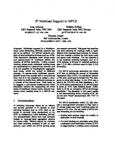
and the receivers are in beams 1, 2, 3 and 6. GW_A1, GW_A2, GW_A3, GW_A4, GW_A5 and GW_A6 serves beams 1, 2, 3, 4, 5 and 6, respectively. The multicast receivers in the terrestrial network as shown in Figure 2 are served through GW_A1. The mobile source sends out just one copy of multicast traffic and the OBP replicates the traffic, one for each of the four beams that has interested receivers. GW handover (GWH), which involves higher layers (i.e., network layer), will take place at the overlapping areas between beams. IP multicast source mobility support is therefore implemented at GWH.
RCST2 (IGMP Proxy)
Satellite OBP - Switching
IGMP Host
IGMP Querier IP
GSE DVB -S
Ethernet
DVB -RCS
10/100 BT
UI
UI
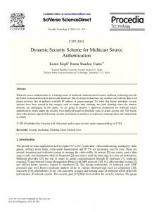
Figure 1. Mesh IP multicast control plane protocol stack [16]
on-board the satellite is defined here at layer 2 of the protocol stack, the knowledge of MAC addresses of the RCSTs is mandatory to establish a connection. This means that the NCC provides the mechanisms required to associate the IP address and MAC address of a RCST/RSGW [16]. In the control plane, Internet Group Management Protocol (IGMP) messages are exchanged between the NCC and the IGMP Proxy contained in the RCSTs. Also, the IGMP messages are exchanged between User Terminals and IGMP Querier included in the RCSTs as shown in Figure 1. IGMPv2 general Query, Specific Group Query, Report and Leave messages are exchanged over the satellite air interface between the NCC and the RCSTs/RSGWs/mRCSTs. As illustrated in Figure 1, all satellite entities transmit using DVB-RCS and receive using DVB by Satellite (DVBS). The two existing satellite transmission standards, DVBRCS and DVB-S are combined by the OBP into a single regenerative multi-spot satellite system allowing a full cross-connectivity between the different up link and down link beams.
B. Source Mobility Support with Multicast Mobility Management Unit (M3U) at Gateway Handover. In order to develop an effective solution to support source mobility, the following general assumptions have been made: • The regenerative satellite has OBP – switching at layer 2 to provide on-board connectivity between different beams. • The NCC will act as the IGMP querier for the satellite network in addition to its normal functionalities. • The NCC enables the establishment of point-tomultipoint connection between mobile source (mRCST) and all listening RCSTs/RSGWs. • All RCSTs function as IGMP Proxy, i.e., IGMP Router and Querier on its user interface (interface towards the internal LAN) and an IGMP Host on the satellite interface. • All RCSTs, mRCSTs and RSGWs are mobility-aware nodes and can process mobility instructions.
A. Network Architecture Figure 2 shows the network architecture, where a mobile multicast source is located at its home network in beam 1 GWH – Gateway Handover
Satellite A
Mobile Source
GWH
RCST1
GW_A1 Beam 1
RCST2
GW_A2 Beam 2
RCST3
GW_A3 Beam 3
Internet
GWH
GWH
GWH
GWH
GW_A4 Beam 4
GW_A5 Beam 5
RCST4
GW_A6 Beam 6
NCC
Multicast Receiver 1 Multicast Receiver 2
Figure 2. Mobile Source at Home Network (GW_A1)
2014, © Copyright by authors, Published under agreement with IARIA - www.iaria.org
International Journal on Advances in Internet Technology, vol 7 no 1 & 2, year 2014, http://www.iariajournals.org/internet_technology/
152
TABLE I. PROPOSED NEW MESSAGES Message Name Service Interface Update Message (SIUM) Source Handover Message (SHM) Channel Update Message (CUM)
Type
Source
Destination
Content IP addresses of mobile source in both old and target GWs. Instructions to update source list (add mobile source new IP address) in service interface of specified channel. A Request to establish point-to-multipoint link btw source & all listening RCSTs/GWs (from previous tree)
Multicast
NCC
All SSM RCSTs/GWs Receivers + mobile source
Internal Signaling
M3U
NCCu
Multicast
Mobile source
All SSM Receivers
IP addresses of mobile source in both old and target GWs. Instructions to receivers to update channel subscription to new mobile source IP address
A new Multicast Mobility Management Unit (M3U) responsible for control plane signaling to provide mobility support for multicast sources is proposed. This new M3U entity located at the NCC is equipped with the following: • A database of all mRCSTs, each identified by its physical (MAC) and IP addresses • A ‘Message Chamber’ which can issue the new proposed signaling messages. Three new types of messages shown on Table I have been proposed in this paper. It is proposed that any mRCST should be able to issue Channel Update Message (CUM) after receiving Service Interface Update Message (SIUM) from the NCC during GWH. Details of these messages are given in Table I. When the NCC receives the synchronization (SYNC) burst from the mobile source (mRCST) containing the handover request, it will retrieve the target beam identity from its database and determine whether the beam belongs to a different GW. Once the NCC establishes that the target beam belongs to a different GW, a GWH is initiated. The NCC will then update its service information (SI) tables which include Terminal Burst Time Plan (TBTP), Superframe Composition Table (SCT), Frame Composition Table (FCT) and Time-slot Composition Table (TCT). The NCC will send an SNMP Set-Request message that includes the updated SI tables and the routing update information (RUI) of the mRCST to the target GW to ensure that the target GW gets ready for connection with the mRCST. Upon reception of the SNMP Set-Request message, the target GW will allocate bandwidth resources and IP address to the mRCST according to the new burst time plan sent by the NCC. The SNMP Get-Response message is then sent by target GW to the NCC. Once the NCC receives the SNMP Get-Response message from target GW, the M3U immediately issues the Source Handover Message (SHM) to the NCC unit (NCCu), requesting the point-to-multipoint link between the source and all the listening RCSTs/GWs (from previous tree). SHM is internal signaling within the NCC (i.e., between M3U and NCCu). Upon reception of SHM, the NCCu will
Purpose To avoid each listening RCST/GW from sending IGMP Join Report on to the satellite air interface after receiving channel resubscription from terrestrial SSM receivers. To establish new delivery tree to all listening RCSTs/GWs without them sending any IGMP join report to new channel (CoA, G). To reduce tree establishment time. For all SSM end receivers to update their channel subscription from (S, G) to CoA, G) For Internet receivers to start building the new delivery tree to the target GW.
make the resources available and then instructs the OBP to establish the required connections. This is immediately followed by the M3U issuing the SIUM to all RCSTs/GWS involved in this particular channel, including the mobile source. The SIUM contains both the mobile source old and new IP addresses in the old and new GWs, respectively. The SIUM also contains instructions for all listening RCSTs/GWs to update source list (add mobile source new IP address) in the service interface for requesting IP multicast reception [17]. This will create a new channel that contains the mobile source new IP address (CoA) under the target GW. This action ensures that subsequently, when the RCSTs/GWs receive IGMP join Report from downstream receivers for this new channel, no IGMP report will be sent to the satellite air interface since the channel already exist in the RCST/GW multicast routing table. The creation of this new channel by the SIUM is possible in satellite networks because the NCC knows: • The mac and IP address of all active RCSTs/GWs, • The newly acquired IP address of the mobile source, • All RCSTs/GWs that are members of the channel involving the mobile source. Therefore, the NCC can enable the establishment of a point-to-multipoint connection between the mobile source and all the listening RCSTs/GWs directly. This reduces the amount of traffic on the satellite air interface, thus saving scarce and expensive satellite bandwidth resources. The PID of the channel may remain the same. Upon reception of SIUM, the mobile source immediately issues CUM, i.e., CUM is triggered by reception of SIUM. The CUM is sent just like any multicast user traffic by the mobile source through source-specific tree to all SSM receivers. After 1 round trip delay of issuing SIUM (for mobile source to receive SIUM and issue CUM), the NCC issues SNMP Set-Request message, which includes the mRCST (mobile source) identity and the SI tables to the source GW. The source GW then acknowledges the NCC by sending a SNMP Get-Response message. Once the SNMP GetResponse message is received from source GW, a GWH command is issued to the mRCST from NCC in a Mobility
2014, © Copyright by authors, Published under agreement with IARIA - www.iaria.org
International Journal on Advances in Internet Technology, vol 7 no 1 & 2, year 2014, http://www.iariajournals.org/internet_technology/
153
Control Descriptor carried in a Terminal Information Message Unicast (TIMu) using the old beam. The source GW now updates its route mapping table and released resources used by the mRCST. Once the mRCST receives the handover command, it synchronizes with the NCC and the target GW, retunes itself to the target beam. Figure 3 shows the proposed signaling sequence to support multicast source mobility for SSM at GWH. This signaling sequence contains the proposed new messages integrated into the standard GWH signaling sequence as described in the DVB-RCS specification in [7]. The NCC acting as satellite IGMP querier keeps control of the multicast groups and also builds the SSM tree based on the on-board connectivity between different beams. Periodically, the NCC sends out the Multicast Map Table (MMT) [16] to all multicast receivers. The MMT which contains the list of IP multicast addresses each associated with a specific Program Identifier (PID) enables listening RCSTs/GWs to receive multicast traffic from groups which they are members of. When the NCC receives an IGMP join report for SSM, the M3U checks the source-list to see if some sources are mRCSTs. If some sources are identified as mRCSTs, the M3U will a keep record of them in its database. Upon reception of CUM by SSM receivers in the Internet, a new SSM delivery tree construction to the target GW is triggered as shown in Figure 4 (compared to that in Figure 2). Figure 4 shows the mobile source now in beam 2 Mobile Source (mRCST)
after a successful GWH. If the Target GW was not a member of the old multicast channel, it will issue an IGMP join report to NCC as soon as it gets the updated channel subscription request (PIM-SSM Join) from receivers in the Internet. The target GW now becomes part of the mesh receivers within the satellite network as it assumes the responsibility of serving receivers in the Internet. But if the target GW was already a member, a multicast reception state will simply be created against the interface upon which the PIM-SSM join was received. It should be noted here that CUM is delivered through serving GW to the SSM receivers in the Internet before the resources used by the mobile source in the serving GW are released and also before retuning and switching by the mobile source to the target GW begins. This is so, because it is only through the serving GW (old SSM delivery tree) that CUM can reach all the SSM receivers in the Internet. When the SSM receivers in the LAN behind the listening RCSTs receive the CUM, they will update their channel subscription by issuing unsolicited IGMP join report towards the RCST. Upon reception of the IGMP join report, the RCST (IGMP Proxy) will check its multicast routing table to see whether that channel already exist. On checking, the RCST will discover the existence of the channel in its multicast routing table thanks to the action of SIUM as described above. Therefore, this will prevent the RCST from issuing IGMP join Report onto the satellite air interface, thus saving satellite bandwidth resources. Internet
GW_A1
NCC
GW_A2
PIM-SSM (a11, G)
IGMP (a11, G) Multicast Traffic
Multicast Traffic
1. SYNC (RL) with HOR 2. SNMP Set-Request: Set SI tables + RUI of mRCST 3. SNMP Set-Response: Set SI tables after BW allocation + IP address to mRCST
M3U 4.SHM
5. SIUM 6. Multicast Traffic: CUM
6. Multicast Traffic: CUM
7. SNMP Set-Request: Set SI tables with mRCST’s Identity 10. TIMu ( F/L) received in old beam, retuned to target beam & switched to new link
8. SNMP Set-Response: Set SI tables
9. PIM-SSM (a12, G)
11. SI tables (TBTP, SCT, FCT, TCT, MMT) 12. ACQ (RL) 13. CMT (FL)
14. IGMP (a12, G) 15. MMT Multicast Traffic Multicast Traffic
Satellite Communication
Terrestrial/wired Communication
a12- mobile source IP address under GW_A2
a11- mobile source IP address under GW_A1
RUI- Routing Update Information; BW - Bandwidth
Figure 3. Signaling sequence at GWH
2014, © Copyright by authors, Published under agreement with IARIA - www.iaria.org
International Journal on Advances in Internet Technology, vol 7 no 1 & 2, year 2014, http://www.iariajournals.org/internet_technology/
154
GWH – Gateway Handover
Satellite A
Mobile Source
GWH
RCST1
RCST2
GW_A1 Beam 1
RCST3
GWH
GWH
GWH
GWH
Internet
RCST4
GW_A5 Beam 5
GW_A4 Beam 4
GW_A3 Beam 3
GW_A2 Beam 2
GW_A6 Beam 6
NCC
Multicast Receiver 1 Multicast Receiver 2
Figure 4. Mobile source at foreign network (GW_A2)
• Target GW signaling (SNMP) to get the mRCST newly allocated IP address.
C. M3U operation and processing Figure 5 shows the processing flowchart of the control plane information (signaling traffic) through the M3U. For correct signaling to take place, M3U must be able to identify the following: • An IGMP packet (i.e., an unsolicited IGMP join report) in order to add the requesting RCST/GW on the delivery tree. • Mobile multicast source or receiver (mRCST) and differentiate between the two. • GWH request and target GW.
1) IGMP Packet Identification When the NCC receives any signaling traffic, the M3U checks the IP destination address and the protocol number on the IP packet to determine whether it is an IGMP packet. If the IP destination address is equal to 224.0.0.1 (for IGMPv1&2) or 224.0.0.22 (for IGMPv3) and the protocol number is equal to 2, then the IP packet is an IGMP packet and is then it is sent to Stage 2 in Figure 5, otherwise, it is sent to Stage 4.
From OBP to NCC
Signalling traffic
NCC M3U
Stage 1 : IGMP packet No
Stage 4 : mRCSTs
Is Dest IP addr + protocol NO = 224.0.0.22 (or G addrs) + proto no 2
identification
signalling detection Is SRC Mac/IP addrs = that of any mRCST
No
Yes
Data Base
Does any mac/IP addrs in SRC-list = mRCST mac/IP addrs
No
Stage 5: SYNC
Yes
IGMP
Stage 3 : Establishing list of active mobile multicast Sources
Record mRCSTs in SRC- list of IGMP Report as mobile SRCs.
IGMP
Burst detection SYNC Burst with handover recommendation?
No
Yes
Stage 6 : Target GW Signalling detection Is SRC
No
Stage 2: Mobile source (mRCST) identification
Yes
Mac/IP addrs = Mac/IP addrs of Target GW
Yes
Get target GW Mac/IP addrs
SYNC Burst
Signals for SHM & SIUM
Message Chamber
IGMP
SHM
Stage 7: Target GW Is Dest port Number = 161 (SNMP)
GWH signalling response (SNMP) detection Yes SNMP
Stage 8 : Get allocated IP addrs of mRCST
SIUM
Record allocated IP addrs of mRCST
SNMP No
NCC Unit T
To Sat
SRC – Source; Addrs – Address; Dest – Destination; Proto no – Protocol number
Figure 5. M3U source mobility support processing for SSM during GWH
2014, © Copyright by authors, Published under agreement with IARIA - www.iaria.org
International Journal on Advances in Internet Technology, vol 7 no 1 & 2, year 2014, http://www.iariajournals.org/internet_technology/
155
2) mRCST Identification In Stage 2 of Figure 5, the task is to determine whether the source-list in the received IGMP packet contains any mobile source (mRCST). The M3U checks the IP addresses contained in the source-list against the list of mRCSTs in the database to find out whether the requesting RCST/GW is requesting to receive multicast traffic from a mobile source (mRCST) or not. If source-list contains any mRCSTs, then those mRCSTs are mobile multicast sources. The mRCSTs contained in source-list of received IGMPv3 join report are then recorded in Stage 3 as mobile sources based on the analysis in Stage 2 given above. Finally, the IGMP packet is then forwarded to the NCC (querier). 3) mRCST Signaling Detection At Stage 4, the main task is to separate signaling traffic coming from any mRCST from those of fixed RCST. To do this, the M3U has to check the source mac/IP address of the signaling traffic received against the database to establish whether it is coming from a mRCST or not. All signaling traffic coming from any mRCST is sent to Stage 5 for close examination to find out whether they are synchronisation (SYNC) burst containing handover recommendation while the rest is sent to Stage 6. Once it is confirmed that it is a SYNC burst in Stage 5, with handover recommendation, then the target GW identity is known and its MAC/IP address recorded. Following this process, a table of mRCST versus target GW (identified by their MAC/IP addresses) can be established for all mRCSTs in the whole interactive satellite network. This now prepares the M3U to expect GWH signaling response from the target GW. 4) Target GW Response Detection and the mRCST allocated IP address recording Now, knowing the identity of the target GW (from the handover recommendation), signaling traffic from the target GW can be tracked within the NCC to find out whether it is the response to the GWH request initiated by the NCC. This is very important because earlier knowledge of the allocated IP address to the mRCST by the target GW contained in this GWH response is very crucial here for further signaling. Therefore, Stage 6 examines the source MAC/IP address of all signaling traffic to see whether it is that of the target GW. If it does, then the packet is sent to Stage 7, if not, then to NCCu. In Stage 7, the destination port number of the packet is checked to find out whether it is equal to that of SNMP (i.e., 161), the signaling protocol used in GWH as specified in [7]. If this is so, then, the packet is sent to Stage 8, where the allocated IP address to the mRCST in the target beam is extracted and recorded. Once the M3U is aware of the mRCST’s IP address in the target beam, it immediately issues the SHM to the NCCu, requesting for a point-tomultipoint connection establishment as explained above. It is therefore imperative that the M3U gets the mRCST’s IP address in the target beam as soon as possible in order to minimise the multicast handover latency during GWH. If
the destination port is not equal to 161, then, the packet is simply sent to the NCCu for normal signaling. The issuing of SHM is immediately followed by that of SIUM to all mesh SSM receivers including the mobile source as explained above. The uniqueness about this proposal are: the new resubscription mechanism of the satellite receivers and gateways to the new multicast channel (CoA, G) after every GW handover without the issuing of IGMP join report over the satellite air interface, the absence of encapsulation (tunnelling) and triangular routing paths throughout the system and its compliance with DVB-RCS/S2 specifications. If all the listening RCSTs/GWs were to individually issue IGMP join reports to the satellite air interface for re-subscription after GWH, the total number would be enormous and will put a lot of strain on the satellite bandwidth resources. The proposed solution will significantly save satellite bandwidth resources. IV.
ANALYTICAL MODEL
Under this section, analytical models for GWH signaling cost and packet delivery cost (when mobile source is away from home) are developed to evaluate the proposed mobile multicast source GWH procedure for SSM. These are then compared with MIP HS–based approach (see Section II), which appears to require only minimal changes to support multicast source mobility for SSM in a satellite environment. The other schemes for multicast source mobility SSM which are mainly defined for terrestrial networks will require major changes to be applicable in satellite networks. This explains why the performance evaluation of the proposed M3U scheme is compared only with that of the MIP HS-based approach. TABLE II. MESSAGE SIZE AND NUMBER OF HOPS Notation Description MSYNC SYNC message size MSNMP SNMP Request/Response + SI tables message sizes + RUI + allocated BW and IP address MTIM Terminal Information Message size MSI_t SI tables (TBTP, SCT, FCT, TCT, MMT) message size MACQ Acquisition Burst message size MCMT Correction Message Table size MMMT Multicast Map Table message size MSIUM Service interface update message size MSHM Source handover message size MCUM Channel update message size MPIM_SM PIM-SM message size MIGMP IGMP message size MDHCP DHCPDISCOVERY/DHCPOFFER/ DHCPRQUEST/DHCPACK message size MMIP_Reg MIPv4 Registration Request message size MMIP_Rep MIPv4 Registration Reply message size MIPv4 Size of IPv4 packet header MDATA Multicast data size h2ST Number of hops between any 2 satellite terminals hGW- INT Number of hops between satellite GW and Internet nodes through internet
2014, © Copyright by authors, Published under agreement with IARIA - www.iaria.org
Value 12 bytes 636 bytes 35 bytes 152 bytes 12 bytes 30 bytes 30 bytes 50 bytes 30 bytes 50 bytes 64 bytes 64 bytes 300 bytes 74 bytes 48 bytes 20 bytes 120 bytes 1 10
International Journal on Advances in Internet Technology, vol 7 no 1 & 2, year 2014, http://www.iariajournals.org/internet_technology/
156
In this analysis, signaling cost (Csign) and the packet delivery cost (CPD) before and after GWH are evaluated. Signaling cost is defined as the accumulative signaling overhead for supporting mobile multicast source GWH in a multi-beam satellite network and is calculated as the product of the size of mobility (handover) signaling messages and their hop distances [18]. Packet delivery cost (CPD) on the other hand is the accumulative traffic overhead incurred in delivering a packet along a routing path. CPD is calculated by multiplying the data packet size by the hop distance. Here, only the packet delivery cost within the satellite network (satellite receivers) will be considered before and after the GWH for both our scheme and the MIP HS–based approach. Table II shows the messages sizes and number of hops used for the analysis. These parameters are referenced from [1][19][20]. The hop distance between any two satellite terminals under different GWs is assumed to be 1. This is because each GW has a different IP address space, hence a different IP network. A. Modelling the Proposed M3U scheme Figure 6 shows the signaling messages (extracted from Figure 3) involved in the proposed M3U scheme for multicast source mobility support. It is assumed here that the target GW was not yet a member of the multicast channel served by the mobile source, so an IGMP join report is issued by the target GW to NCC after receiving an updated channel subscription request (PIM-SSM Join) from receivers in the Internet (see Figures 2 and 4). It is also assumed in Figure 6 that SNMP–Request and SNMPResponse messages carrying the SI tables, RUI and allocated bandwidth resources + IP address have the same packet length or size. From Figure 6, the signaling cost per M 3U ) GWH for the proposed M3U scheme C (sign is given by: ( M 3U ) = C SYNC + 4C SNMP + C SIUM + CCUM + C PIM − SM C sign
. (1)
+ CTIM + C SI − t + C ACQ + CCMT + C IGMP + C MMT
Where each of the terms in (1) represents the cost of each signaling message shown in Figure 6. mRCST
GW_A1
NCC SYNC (RL)
Terrestrial Networks
GW_A2
Substituting the cost value (message size × hop distance) for ( M 3U ) each term in (1) and re-arranging implies C sign is given by: ( M 3U ) αh (M = 2ST SYNC + 4M SNMP + M SIUM + MCUM + MTIM + M SI _ t + M ACQ . (2) C sign
+ MCMT + M IGMP + M MMT) + βhGW _ INT (MCUM + M PIM _ SM )
Where α and β are weighting factors for wireless (satellite) and wired links, respectively. They are used to emphasize the link stability [18][21]. ( M 3U ) The packet delivery cost C PD for each multicast packet to any receiver within the satellite network (i.e., mesh communication) is given by: ( M 3U ) = α M DATA h 2 S T . C PD
(3)
The packet delivery cost before and after GWH under this scheme will remain the same. This is because no extra hop will be traversed by the packet after GWH. ( M 3U ) The packet delivery cost per multicast session C PDS can be determined using the average session transmission rate λ S , from the mobile source and the average session length in packets E S [18][22] . This is calculated as the ( M 3U ) product of λ S , E S and C PD (i.e., the packet delivery cost for one multicast packet). This implies packet delivery ( M 3U ) cost per multicast session C PDS is given by [18] [22]:
( M 3U ) ( M 3U ) = λ S E S C PD . C PDS
(4)
B. Modelling of MIP HS-based approach The MIP HS or bi-directional tunnelling approach relies on mobile IP architectural entities, i.e., HA and mobile node (mRCST). When the mobile source moves away from its home network at GW_A1 to a foreign network at GWA_2, it has to register its care-of address [23] to its HA at home network. mRCST
NCC
GW_A1
SYNC
Terrestrial Networks
GW_A2
SNMP- Request
SNMP- Request
SNMP- Response
SNMP- Response
SNMP- Request L2H
SIUM
SNMP- Response TIMu
CUM
SI Tables ACQ
SNMP- Request
CMT
SNMP- Response
PIM-SSM (a13, G)
TIMu
L3H
SI Tables ACQ CMT
DHCPDISCOVER DHCPOFFER DHCPREQUEST DHCPACK
MIPv4 Reg Request
IGMP (a12, Join MMT
MIPv4 Reg
MIPv4 Reg Reply Multicast Traffic
L2H – Layer 2 handover signalling; L3H - Layer 3 handover signalling; MIPv4 Reg – MIPv4 Registration signalling
Figure 6. Signaling messages when using M3U
Figure 7. Signaling messages when using MIP HS-based approach
2014, © Copyright by authors, Published under agreement with IARIA - www.iaria.org
International Journal on Advances in Internet Technology, vol 7 no 1 & 2, year 2014, http://www.iariajournals.org/internet_technology/
157
Details of MIP HS-based approach can be found in [3]. Figure 7 shows the signaling messages involved during GWH using MIP HS-based approach. The details of the content of Figure 7 can be found in [7][19][23][24] . Similarly as in (1) and (2) above, the signaling cost per ( HS ) GWH for MIP HS-based approach, C sign is given by: ( HS ) = C sign
C SYNC + 4C SNMP + C TIM + C SI − t + C ACQ + C CMT
The total signaling cost C T _ Sign to support the multicast source mobility is therefore given by the product of the signaling cost per GWH and the frequency of GWH. So, from (2) and (10), the total signaling cost for the proposed M3U scheme C T _ Sign is given by: U) = C T( M_ 3Sign
. (5)
+ 4C DHCP + C MIP − Re q + C MIP − Re p + 2C T
Where CT is the cost of tunnelling each IPv4 packet header. ( HS ) αh2ST (M SYNC + 4M SNMP + MTIM + M SI _ t + M ACQ = C sign
.
(6)
packet to any receiver within the satellite network (i.e., mesh communication) before GWH in MIP HS-based approach is given by:
) = C T( HS _ Sign
2V ( HS ) C sign . πR
C
( HS ) PD _ after
= α h 2 ST ( 2 M Data + M IPv 4 ) .
(8)
Signalling Cost per GWH (bytes hops)
(7)
After GWH, the packet delivery routing path changes as the mobile source has to first tunnel the multicast data to its HA at home network for delivery into the source-specific tree. This implies the multicast data will under a double hop communication from the mobile source to reach the listening RCSs/RSGWs. Hence, the packet delivery cost ( HS ) after GWH C PD is given by: _ after
(12)
For numerical evaluations, the parameters in Table II and the following are used in the analytical models presented in Section IV: E S = 10, α = 2, β = 1 [18][21]. 8400
( HS ) = α M DATA h 2 ST . C PD _ before
(11)
Similarly, from (6) and (10), the total signaling cost for MIP HS-based approach is given by:
+ MCMT + 4M DHCP + MMIP−Re q + MMIP−Re p + 2M I Pv4 )
( HS ) The packet delivery cost C PD for each multicast _ brfore
2V ( M 3U ) C sign . πR
MIP HS
8200 8000 7800 7600 7400 7200
Proposed M3U
7000 6800 6600 6400 1
Similarly as in (4), the packet delivery cost per multicast session after GWH for MIP HS-based approach is given by:
Different Schemes
Figure 8. Comparison of signaling cost at GWH
C
( HS ) PD _ after
= λS ES C
( HS ) PD _ after
.
(9)
R = 5000 Km
1200 Proposed M3U
NUMERICAL ANALYSIS AND RESULTS
1000
Assuming here that the satellite beams (coverage area) are circular and of identical dimensions, the border crossing rate of the mobile source (mRCST) or in other words, the frequency at which GWH is taking place f GWH is given by [18][22]:
f GWH =
2V . πR
(10)
Total Signalling Cost (bytes hops)
V.
MIP HS
800
600
400
200
0
Where V is the average velocity of the mobile source and R is the radius of the circular satellite beam.
0
100
200
300
400
500
600
700
800
900
Velocity (Km/h)
Figure 9. Variation of total signaling cost with velocity
2014, © Copyright by authors, Published under agreement with IARIA - www.iaria.org
1000
International Journal on Advances in Internet Technology, vol 7 no 1 & 2, year 2014, http://www.iariajournals.org/internet_technology/
158
6000 Proposed M3U
Proposed M3U
MIP HS
MIP HS
2000
5000
Packet Delivery Cost (bytes hops)
Toatal Signalling Cost (bytes hops)
V = 750 Km/h
1500
1000
500
0 2000 4000 6000 8000 10000 12000 14000 16000 18000 20000 22000
Radius (Km)
Figure 10. Variation of total signaling cost with radius
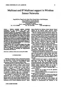
A. Signaling Cost Figure 8 shows the signaling cost at GWH for the proposed M3U scheme as compared with the MIP HS-based approach. These results are obtained by substituting the numerical values of the parameters in (2) and (6), respectively. From Figure 8, it can be seen that signaling cost of the MIP HS-based approach is much higher than that in the proposed M3U scheme. The extra signaling cost for location update at the HA is one of the major reasons for the higher GWH signaling cost in MIP HS-based approach. By making use of (11) and (12), the total signaling cost during GWHs for the proposed M3U and MIP HS-based schemes, respectively, are investigated in Figures 9 and 10. In Figure 9, the radius of the satellite beam is set at 5000 Km and the total signaling cost is measured as the velocity of the mRCST (mobile source) is varied from 0 to 1000Km/h. Figure 9 reveals that the total signaling cost increases as the velocity of the mobile source increases. This is expected, since the higher the velocity, the more the frequency of GWH (border crossing) and hence, the higher total signaling cost. It can also be deduced from Figure 9 that the total signaling cost for MIP HS-based approach is generally higher than that for the proposed M3U scheme. These results show that in a similar multi-beam satellite network providing mobility support, satellite terminals on slow moving platforms like the maritime vessels will incur less signaling cost (overhead) than those on fast moving platforms like long haul flights (aircrafts). On the other hand, Figure 10 shows how the total signaling cost changes with varying satellite beam radius at a fixed mobile source velocity of 750Km/h. As shown in Figure 10, the total signaling cost reduces as the radius of the satellite beam increases. This is true because the larger the satellite beams (radius), the fewer the number of GWHs required by the mobile source travelling at a constant velocity. But the smaller the satellite beam, the more the number of GWHs required for any satellite terminal travelling at a constant speed.
4000
3000
2000
1000
0 0
0.1
0.2
0.3
0.4
0.5
0.6
0.7
0.8
0.9
1
Session Transmission Rate
Figure11. Comparison of packet delivery cost
More GWHs implies more signaling cost and vice versa. Although the recent trend in satellite beam size is moving towards narrow beams instead of big beams, the main reasons are the power requirements of the RCST and the frequency reuse (to increase capacity). Figure 10 also shows that the proposed M3U scheme outperforms the MIP HSbased approach in total signaling cost against radius of satellite beam. The results in Figure 10 could be particularly important to designers of global multi-beam satellite networks that support mobility, as the sizes of the GW beams will have an effect on the overall handover overhead. B. Packet Delivery Cost The packet delivery cost for both schemes after GWH obtained by making use of (4) and (9), are investigated in Figure 11. The display in Figure 11 shows that packet delivery cost increases as the session transmission rate increases. Also, Figure 11 shows that for any particular session transmission rate, the packet delivery cost for MIP HS-based approach is much higher than that for the proposed M3U scheme. This is consistent with the fact that in the proposed M3U scheme, there is mesh communication with a single hop over the satellite even when the mobile source is away from home and also, there is no encapsulation (tunnelling) of multicast packet at all in any stage. But in MIP HS-based approach, packet delivery has to undergo a double hop transmission over satellite (i.e., through HA), thus incurring higher packet delivery cost. Also, the higher multicast packet delivery cost in MIP HSbased approach when the mobile source is away from home is due to the fact that tunnelling is employed to route packets between the mobile source and the HA. The extra IP packet header here increases the packet delivery cost. From all the results presented in Figures 8, 9, 10 and 11, the proposed M3U scheme outperforms the MIP HS-based approach.
2014, © Copyright by authors, Published under agreement with IARIA - www.iaria.org
International Journal on Advances in Internet Technology, vol 7 no 1 & 2, year 2014, http://www.iariajournals.org/internet_technology/
159
VI.
CONCLUSION AND FUTURE WORK
Support for IP mobile multicast over bandwidth constrained environments like satellites is very important, as it efficiently makes use of the available bandwidth resources and thus provide cost effective network services. Due to transparency and reverse path forwarding problems, the handover of a mobile multicast source in SSM from one IP network to another will result to the breakage of the multicast delivery tree. While some solutions to support multicast source mobility in SSM have been proposed for the internet, it was seen that these are not very suitable in a satellite network. This paper proposes a suitable solution for multicast source mobility for SSM in a multi-beam satellite network. It presents the network architecture and proposes a new Multicast Mobility Management Unit (M3U) located at the NCC. Also, three new control messages have been proposed to provide IP mobility support to the mobile multicast source during GWH. The functioning of the M3U and the new control messages provide an elegant and effective solution for the mobile multicast source transparency and RPF problems in SSM. Performance evaluation for the proposed M3U scheme and the MIP HS-based approach was carried out using signaling cost during GWH handover and packet delivery cost after GWH. Provided other factors remain constant, the results obtained show the following: • The total GWH signaling cost is directly proportional to the speed of the mobile source, i.e., the higher the speed, the higher the total GWH signaling cost and vice versa. • The total GWH signaling cost is inversely proportional to the radius of the satellite (gateway) beam, i.e., the total GWH signaling cost reduces as the radius of the satellite beam increases and vice versa. • The packet delivery cost is directly proportional to the session transmission rate. This means that the packet delivery cost increases as the session transmission rate increases and reduces as the session transmission rate reduces. In all scenarios investigated, the results obtained show that the proposed M3U scheme outperformed the MIP HS-based approach in terms of total GWH signaling cost and packet delivery cost when the mobile source is away from home network. For future work, ways of integrating the proposed M3U scheme into PMIPv6-based IP mobility over satellite will be examined. This could potentially lead to faster and better handover performance compared to the individual M3U or PMIPv6 scheme.
[2]
[3]
[4]
[5] [6] [7]
[8]
[9]
[10]
[11]
[12]
[13]
[14]
[15]
[16]
REFERENCES [1]
E. K. Jaff, P. Pillai, and Y. F. Hu, "Source mobility support for source specific multicast in satellite setworks," in MOBILITY 2013 : The Third International Conference on Mobile Services, Resources, and Users, Lisbon, Portugal, 2013, pp. 69 - 74.
[17]
H. Holbrook, B. Cain, and B. Haberman, "Using internet group management protocol version 3 (IGMPv3) and multicast listener discovery protocol version 2 (MLDv2) for source-specific multicast," IETF RFC 4604, August 2006. I. Romdhani, M. Kellil, L. Hong-Yon, A. Bouabdallah, and H. Bettahar, "IP mobile multicast: challenges and solutions," Communications Surveys & Tutorials, IEEE, vol. 6, pp. 18-41, First Quarter 2004. P. Ferguson and D. Senie, "Network ingress filtering: defeating denial of service attacks which employ IP source address spoofing," IETF RFC 2827, May 2000. "DVB fact sheet- August 2012: return channel satellite," DVB Project Fact Sheet, August 2012. "SatNet DVB-RCS vs. proprietary VSAT systems," Advantech Satellite Networks DVB-RCS, April 2006. "Digital video broadcasting (DVB); interaction channel for satellite distribution systems; guidelines for the use of EN 301 790 in mobile scenarios," ETSI TR 102 768, April 2009. I. Romdhani, H. Bettahar, and A. Bouabdallah, "Transparent handover for mobile multicast sources," in Networking, International Conference on Systems and International Conference on Mobile Communications and Learning Technologies, 2006. ICN/ICONS/MCL 2006. International Conference on, 2006, pp. 145-145. T. C. Schmidt and M. Wählisch, "Extending SSM to MIPv6—problems, solutions and improvements," in selected papers from TERENA Networking Conference, Computational Methods in Science and Technology, Poznań, 2005, pp. 147-152. T. C. Schmidt, M. Wählisch, and M. Wodarz, "Fast adaptive routing supporting mobile senders in source specific multicast," Telecommunication Systems, Springer, vol. 43, pp. 95 – 108, February 2010. C. S. Jelger and T. Noel, "Supporting mobile SSM sources for IPv6," in Global Telecommunications Conference, 2002. GLOBECOM '02. IEEE, November 2002, pp. 16931697. T. C. Schmidt, S. Gao, H. Zhang, and M.Waehlisch, "Mobile multicast sender support in proxy mobile IPv6 (PMIPv6) domains," IETF, draft-ietf-multimob-pmipv6source-03, February 2013. B. Fenner, H. He, B. Haberman, and H. Sandick, "Internet group management protocol (IGMP)/multicast listener discovery (MLD)-based multicast forwarding ("IGMP/MLD proxying")," IETF RFC 4605, August 2006. S. Gundavelli, K. Leung, V. Devarapalli, K. Chowdhury, and B. Patil, "Proxy mobile IPv6," IETF RFC 5213, August 2008. "Satellite earth stations and systems (SES); broadband satellite multimedia (BSM); connection control protocol (C2P) for DVB-RCS; background information," ETSI TR 102 603, January 2009. "Satellite earth stations and systems (SES); broadband satellite multimedia (BSM); regenerative satellite mesh - B (RSM-B); DVB-S/DVB-RCS family for regenerative satellites; Part 2: satellite link control layer," ETSI TS 102 429-2, October 2006. B. Cain, S. Deering, I. Kouvelas, B. Fenner, and A. Thyagarajan, "Internet group ganagement protocol, version 3," IETF RFC 3376, October 2002.
2014, © Copyright by authors, Published under agreement with IARIA - www.iaria.org
International Journal on Advances in Internet Technology, vol 7 no 1 & 2, year 2014, http://www.iariajournals.org/internet_technology/
160
[18]
[19]
[20]
[21]
L. Jong-Hyouk, T. Ernst, and C. Tai-Myoung, "Cost analysis of IP mobility management protocols for consumer mobile devices," Consumer Electronics, IEEE Transactions on, vol. 56, pp. 1010-1017, 2010. "Digital video broadcasting (DVB); transport of MPEG-2 TS based DVB services over IP based networks," ETSI TS 102 034 V1.3.1, October 2007. X. Jiang and U. Narayanan, "Performance analysis of mobility support in IPv4/IPv6 mixed wireless networks," Vehicular Technology, IEEE Transactions on, vol. 59, pp. 962-973, 2010. J. H. Lee, T. Ernst, D. J. Deng, and H. C. Chao, "Improved PMIPv6 handover procedure for consumer multicast
[22]
[23] [24]
traffic," Communications, IET, vol. 5, pp. 2149-2156, 2011. L. Jong-Hyouk, J. M. Bonnin, Y. Ilsun, and C. TaiMyoung, "Comparative handover performance analysis of IPv6 mobility management protocols," Industrial Electronics, IEEE Transactions on, vol. 60, pp. 1077-1088, 2013. C. Perkins, "IP mobility support for IPv4," IETF RFC 3344, Aug. 2002. "Digital video broadcasting (DVB); guidelines for DVB IP phase 1 handbook," ETSI TR 102 542, November 2006.
2014, © Copyright by authors, Published under agreement with IARIA - www.iaria.org