The New Architecture. If a person walks fast on a road covering fifty miles in ... Intel, and AMD have all changed their
Professional
Multicore Programming Design and Implementation for C++ Developers Cameron Hughes Tracey Hughes
Wiley Publishing, Inc.
The New Architecture If a person walks fast on a road covering fifty miles in a day, this does not mean he is capable of running unceasingly from morning till night. Even an unskilled runner may run all day, but without going very far. —Miyamoto Musahi, The Book of Five Rings
The most recent advances in microprocessor design for desktop computers involve putting multiple processors on a single computer chip. These multicore designs are completely replacing the traditional single core designs that have been the foundation of desktop computers. IBM, Sun, Intel, and AMD have all changed their chip pipelines from single core processor production to multicore processor production. This has prompted computer vendors such as Dell, HP, and Apple to change their focus to selling desktop computers with multicores. The race to control market share in this new area has each computer chip manufacturer pushing the envelope on the number of cores that can be economically placed on a single chip. All of this competition places more computing power in the hands of the consumer than ever before. The primary problem is that regular desktop software has not been designed to take advantage of the new multicore architectures. In fact, to see any real speedup from the new multicore architectures, desktop software will have to be redesigned. The approaches to designing and implementing application software that will take advantage of the multicore processors are radically different from techniques used in single core development. The focus of software design and development will have to change from sequential programming techniques to parallel and multithreaded programming techniques. The standard developer ’s workstation and the entry-level server are now multiprocessors capable of hardware-level multithreading, multiprocessing, and parallel processing. Although sequential programming and single core application development have a place and will remain with us, the ideas of multicore application design and development are now in the mainstream.
Chapter 1: The New Architecture This chapter begins your look at multicore programming. We will cover: ❑
What is a multicore?
❑
What multicore architectures are there and how do they differ from each other?
❑
What do you as a designer and developer of software need to know about moving from sequential programming and single core application development to multicore programming?
What Is a Multicore? A multicore is an architecture design that places multiple processors on a single die (computer chip). Each processor is called a core. As chip capacity increased, placing multiple processors on a single chip became practical. These designs are known as Chip Multiprocessors (CMPs) because they allow for single chip multiprocessing. Multicore is simply a popular name for CMP or single chip multiprocessors. The concept of single chip multiprocessing is not new, and chip manufacturers have been exploring the idea of multiple cores on a uniprocessor since the early 1990s. Recently, the CMP has become the preferred method of improving overall system performance. This is a departure from the approach of increasing the clock frequency or processor speed to achieve gains in overall system performance. Increasing the clock frequency has started to hit its limits in terms of cost-effectiveness. Higher frequency requires more power, making it harder and more expensive to cool the system. This also affects sizing and packaging considerations. So, instead of trying to make the processor faster to gain performance, the response is now just to add more processors. The simple realization that this approach is better has prompted the multicore revolution. Multicore architectures are now center stage in terms of improving overall system performance. For software developers who are familiar with multiprocessing, multicore development will be familiar. From a logical point of view, there is no real significant difference between programming for multiple processors in separate packages and programming for multiple processors contained in a single package on a single chip. There may be performance differences, however, because the new CMPs are using advances in bus architectures and in connections between processors. In some circumstances, this may cause an application that was originally written for multiple processors to run faster when executed on a CMP. Aside from the potential performance gains, the design and implementation are very similar. We discuss minor differences throughout the book. For developers who are only familiar with sequential programming and single core development, the multicore approach offers many new software development paradigms.
Multicore Architectures CMPs come in multiple flavors: two processors (dual core), four processors (quad core), and eight processors (octa-core) configurations. Some configurations are multithreaded; some are not. There are several variations in how cache and memory are approached in the new CMPs. The approaches to processor-to-processor communication vary among different implementations. The CMP implementations from the major chip manufacturers each handle the I/O bus and the Front Side Bus (FSB) differently.
2
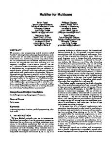
Chapter 1: The New Architecture Again, most of these differences are not visible when looking strictly at the logical view of an application that is being designed to take advantage of a multicore architecture. Figure 1-1 illustrates three common configurations that support multiprocessing.
MULTICORE (CMP) HYPERTHREADED PROCESSOR
PROCESSOR 1
PROCESSOR 2 ALU
ALU LOGICAL PROCESSOR 1
LOGICAL PROCESSOR 2
ALU
REGISTERS
SHARED CPU COMPONENTS
shared logical processor on same chip
FSB
CONFIGURATION 1
FETCH/ DECODE UNIT
ALU
REGISTERS
L1 CACHE
L2 CACHE
FETCH/ DECODE UNIT
REGISTERS
FETCH/ DECODE UNIT
REGISTERS
FETCH/ DECODE UNIT
L1 CACHE
L1 CACHE
L1 CACHE
L2 CACHE
multiple processors on separate chip
L2 CACHE
FSB
CONFIGURATION 2
L2 CACHE
multiple processors in a package (chip)
FSB
CONFIGURATION 3
Figure 1-1
❑
Configuration 1 in Figure 1-1 uses hyperthreading. Like CMP, a hyperthreaded processor allows two or more threads to execute on a single chip. However, in a hyperthreaded package the multiple processors are logical instead of physical. There is some duplication of hardware but not enough to qualify a separate physical processor. So hyperthreading allows the processor to present itself to the operating system as complete multiple processors when in fact there is a single processor running multiple threads.
❑
Configuration 2 in Figure 1-1 is the classic multiprocessor. In configuration 2, each processor is on a separate chip with its own hardware.
❑
Configuration 3 represents the current trend in multiprocessors. It provides complete processors on a single chip.
As you shall see in Chapter 2, some multicore designs support hyperthreading within their cores. For example, a hyperthreaded dual core processor could present itself logically as a quad core processor to the operating system.
Hybrid Multicore Architectures Hybrid multicore architectures mix multiple processor types and/or threading schemes on a single package. This can provide a very effective approach to code optimization and specialization by combining unique capabilities into a single functional core. One of the most common examples of the hybrid multicore architecture is IBM’s Cell broadband engine (Cell). We explore the architecture of the Cell in the next chapter.
3
Chapter 1: The New Architecture What’s important to remember is that each configuration presents itself to the developer as a set of two or more logical processors capable of executing multiple tasks concurrently. The challenge for system programmers, kernel programmers, and application developers is to know when and how to take advantage of this.
The Software Developer ’s Viewpoint The low cost and wide availability of CMPs bring the full range of parallel processing within the reach of the average software developer. Parallel processing is no longer the exclusive domain of supercomputers or clusters. The basic developer workstation and entry-level server now have the capacity for hardwareand software-level parallel processing. This means that programmers and software developers can deploy applications that take advantage of multiprocessing and multithreading as needed without compromising design or performance. However, a word of caution is in order. Not every software application requires multiprocessing or multithreading. In fact, some software solutions and computer algorithms are better implemented using sequential programming techniques. In some cases, introducing the overhead of parallel programming techniques into a piece of software can degrade its performance. Parallelism and multiprocessing come at a cost. If the amount of work required to solve the problem sequentially in software is less than the amount of work required to create additional threads and processes or less than the work required to coordinate communication between concurrently executing tasks, then the sequential approach is better. Sometimes determining when or where to use parallelism is easy because the nature of the software solution demands parallelism. For example, the parallelism in many client-server configurations is obvious. You might have one server, say a database, and many clients that can simultaneously make requests of the database. In most cases, you don’t want one client to be required to wait until another client’s request is filled. An acceptable solution allows the software to process the clients’ requests concurrently. On the other hand, there is sometimes a temptation to use parallelism when it is not required. For instance, you might be tempted to believe that a keyword word search through text in parallel will automatically be faster than a sequential search. But this depends on the size of text to be searched for and on the time and amount of overhead setup required to start multiple search agents in parallel. The design decision in favor of a solution that uses concurrency has to consider break-even points and problem size. In most cases, software design and software implementation are separate efforts and in many situations are performed by different groups. But in the case where software speedup or optimal performance is a primary system requirement, the software design effort has to at least be aware of the software implementation choices, and the software implementation choices have to be informed by potential target platforms. In this book, the target platforms are multicore. To take full advantage of a multicore platform, you need to understand what you can do to access the capabilities of a CMP. You need to understand what elements of a CMP you have control over. You will see that you have access to the CMP through the compiler, through operating system calls/libraries, through language features, and through applicationlevel libraries. But first, to understand what to do with the CMP access, you need a basic understanding of the processor architecture.
4
Chapter 1: The New Architecture
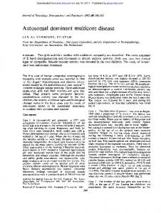
The Basic Processor Architecture The components you can access and influence include registers, main memory, virtual memory, instruction set usage, and object code optimizations. It is important to understand what you can influence in single processor architectures before attempting to tackle multiprocessor architectures. Figure 1-2 shows a simplified logical overview of a processor architecture and memory components.
PROCESSOR
ALU
REGISTERS
L1 CACHE
FETCH/ DECODE UNIT SYSTEM MAIN MEMORY
I/O SUBSYSTEM and DEVICES
L2 CACHE
Figure 1-2
There are many variations on processor architecture, and Figure 1-2 is only a logical overview. It illustrates the primary processor components you can work with. While this level of detail and these components are often transparent to certain types of application development, they play a more central role in bottom-up multicore programming and in software development efforts where speedup and optimal performance are primary objectives. Your primary interface to the processor is the compiler. The operating system is the secondary interface. In this book, we will use C++ compilers to generate the object code. Parallel programming can be used for all types of applications using multiple approaches, from low to high level, from object-oriented to structured applications. C++ supports multiparadigm approaches to programming, so we use it for its flexibility. Table 1-1 shows a list of categories where the compiler interfaces with the CPU and instruction set. Categories include floating-point, register manipulation, and memory models.
5
Chapter 1: The New Architecture Table 1-1 Compiler Switch Options Vectorization
Auto parallelization
Description
Examples of Usage
This option enables the vectorizer, a component of the compiler that automatically uses Single Instruction Multiple Data (SIMD) instructions in the MMX registers and all the SSE instruction sets.
-x
This option identifies loop structures that contain parallelism and then (if possible) safely generates the multithreaded equivalent executing in parallel.
-parallel
Parallelization with OpenMP
With this option the compiler generates multithreaded code based on OpenMP directives in the source code added by the programmer.
Fast
This option detects incompatible processors; error messages are generated during execution.
-ax
Enables the vectorizer.
Triggers auto parallelization.
#pragma omp parallel { #pragma omp for // your code }
-O1 Optimized to favor code size and code locality and disables loop unrolling, software pipelining, and global code scheduling. -O2 Default; turns pipelining ON.
Floating point
Set of switches that allows the compiler to influence the selection and use of floating-point instructions.
-fschedule-insns Tells the compiler that other instructions can be issued until the results of a floating-point instruction are required. -float-store Tells the compiler that when generating object code do not use instructions that would store a floating-point variable in registers.
6
Chapter 1: The New Architecture Compiler Switch Options Loop unrolling
Memory bandwidth
Code generation
Thread checking
Thread library
Description
Examples of Usage
This option enables loop unrolling. This applies only to loops that the compiler determines should be unrolled. If n is omitted, lets the compiler decide whether to perform unrolling or not.
-unroll
This option enables or disables control of memory bandwidth used by processors; if disabled, bandwidth will be well shared among multiple threads. This can be used with the auto parallelization option. This option is used for 64-bit architectures only.
-opt-mem-bandwidth n = 2
With this option code is generated optimized for a particular architecture or processor; if there is a performance benefit, the compiler generates multiple, processorspecific code paths; used for 32- and 64- bit architectures.
-ax
This option enables thread analysis of a threaded application of program; can only be used with Intel’s Thread Checker tool.
-tcheck
This option causes the compiler to include code from the Thread Library; The programmer needs to include API calls in source code.
Enables loop unrolling; sets the maximum time to unroll the loop. n = 0 Disables loop unrolling, only allowable value for 64-bit architectures.
Enables compiler optimizations for parallel code such as pthreads and MPI code. n = 1 Enables compiler optimizations for multithreaded code generated by the compiler. Generates optimized code for the specified processor. -axS Generates specialized code paths using SIMD Extensions 4 (SSE4) vectorizing compiler and media accelerators instructions. Enables analysis of threaded application or program. -pthread Uses the pthread library for multithreading support.
The CPU (Instruction Set) A CPU has a native instruction set that it recognizes and executes. It’s the C++ compiler ’s job to translate C++ program code to the native instruction set of the target platform. The compiler converts the C++ and produces an object file that consists of only instructions that are native to the target processor. Figure 1-3 shows an outline of the basic compilation process.
7
Chapter 1: The New Architecture
C/C++ PROGRAM
compiler switches, directives & parameters -funroll=Value -xcache = Value
loop unrolling, multithread options, etc.
COMPILER
assembler arguments, switches & directives
ASSEMBLY CODE
register usage, pipeline hints, etc.
ASSEMBLER
NATIVE LANGUAGE OF PROCESSOR
Figure 1-3 During the process of converting C++ code into the native language of the target CPU, the compiler has options for how to produce the object code. The compiler can be used to help determine how registers are used, or whether to perform loop unrolling. The compiler has options that can be set to determine whether to generate 16-bit, 32-bit, or 64-bit object code. The compiler can be used to select the memory model. The compiler can provide code hints that declare how much level 1 (L1) or level 2 (L2) cache is present. Notice in Table 1-1 in the floating-point operations category that switches from this category allow the compiler to influence the selection of floating-point instructions. For example, the GNU gcc compiler has the --float-store switch. This switch tells the compiler that when generating object code it should not use instructions that would store floating-point variable in registers. The Sun C++ compiler has a -fma switch. This switch enables automatic generation of floating-point and multi-add instructions. The -fma=none disables generation of these instructions. The -fma=fused switch allows the compiler to attempt to improve the performance of the code by using floating-point, fused, and multiply=add instructions. In both cases, the switches are provided as options to the compiler: gcc
-ffloat-store my_program.cc
or CC -fma=used
my_program.cc
Other switches influence cache usage. For instance the Sun C++ compiler has a -xcache=c that defines the cache properties for use by the optimizer. The GNU gcc compiler has the -Funroll -loops that specifies how loops are to be unrolled. The GNU gcc compiler has a -pthread switch that turns on support for multithreading with pthreads. The compilers even have options for setting the typical
8
Chapter 1: The New Architecture memory reference interval using the -mmemory-latency=time switch. In fact, there are compiler options and switches that can influence the use of any of the components in Figure 1-2. The fact that the compiler provides access to the processor has implications for the developer who is writing multicore applications for a particular target processor or a family of processors. For example, The UltraSparc, Opteron, Intel Core 2 Duo, and Cell processors are commonly used multicore configurations. These processors each support high-speed vector operations and calculations. They have support for the Single Instruction Multiple Data (SIMD) model of parallel computation. This support can be accessed and influenced by the compiler. Chapter 4 contains a closer look at the part compilers play in multicore development. It is important to note that using many of these types of compiler options cause the compiler to optimize code for a particular processor. If cross-platform compatibility is a design goal, then compiler options have to be used very carefully. For system programmers, library producers, compiler writers, kernel developers, and database and server engine developers, a fundamental understanding of the basic processor architecture, instruction set and compiler interface is a prerequisite for developing effective software that takes advantage of CMP.
Memory Is the Key Virtually anything that happens in a computer system passes through some kind of memory. Most things pass through many levels of memory. Software and its associated data are typically stored on some kind of external medium (usually hard disks, CD-ROMs, DVDs, etc.) prior to its execution. For example, say you have an important and very long list of numbers stored on an optical disc, and you need to add those numbers together. Also say that the fancy program required to add the very long list of numbers is also stored on the optical disc. Figure 1-4 illustrates the flow of programs and data to the processor. PROCESSOR
ALU
REGISTERS
L1 CACHE
FETCH/ DECODE UNIT SYSTEM MAIN MEMORY
file of important numbers and fancy programs
L2 CACHE
Figure 1-4
9
Chapter 1: The New Architecture In the maze of different types of memory, you have to remember that the typical CPU operates only on data stored in its registers. It does not have the capacity to directly access data or programs stored elsewhere. Figure 1-4 shows the ALU reading and writing the registers. This is the normal state of affairs. The instruction set commands (native language of the processor) are designed to primarily work with data or instructions in the CPU’s registers. To get your long list of important numbers and your fancy program to the processor, the software and data must be retrieved from the optical disc and loaded into primary memory. From primary memory, bits and pieces of your software and data are passed on to L2 cache, then to L1 cache, and then into instruction and data registers so that the CPU can perform its work. It is important to note that at each stage the memory performs at a different speed. Secondary storage such as CD-ROMs, DVDs, and hard disks are slower than the main random access memory (RAM). RAM is slower than L2 cache memory. L2 cache memory is slower than L1 cache memory, and so on. The registers on the processor are the fastest memory that you can directly deal with. Besides the speed of the various types of memory, size is also a factor. Figure 1-5 shows an overview of the memory hierarchy.
FASTER
CPU 0
REG 0
REG 1
REG 2
ACCESS SPEED
L1 CACHE
REG 3
L2 CACHE
SYSTEM MAIN MEMORY
VIRTUAL MEMORY (EXTERNAL DISK)
I/O DEVICES SLOWER
Figure 1-5
The register is the fastest but has the least capacity. For instance, a 64-bit computer will typically have a set of registers that can each hold up to 64 bits. In some instances, the registers can be used in pairs allowing for 128 bits. Following the registers in capacity is L1 cache and if present L2 cache. L2 cache is
10
Chapter 1: The New Architecture currently measured in megabytes. Then there is a big jump in maximum capacity from L2 to the system main memory, which is currently measured in gigabytes. In addition to the speeds of the various types of memory and the capacities of the various types of memory, there are the connections between the memory types. These connections turn out to have a major impact on overall system performance. Data and instructions stored in secondary storage typically have to travel over an I/O channel or bus to get to RAM. Once in RAM, the data or instruction normally travels over a system bus to get to L1 cache. The speed and capacity of the I/O buses and system buses can become bottlenecks in a multiprocessor environment. As the number of cores on a chip increases, the performance of bus architectures and datapaths become more of an issue. We discuss the bus connection later in this chapter, but first it’s time to examine the memory hierarchy and the part it plays in your view of multicore application development. Keep in mind that just as you can use the influence that the compiler has over instruction set choices, you can use it to manipulate register usage and RAM object layouts, give cache sizing hints, and so on. You can use further C++ language elements to specify register usage, RAM, and I/O. So, before you can get a clear picture of multiprocessing or multithreading, you have to have a fundamental grasp of the memory hierarchy that a processor deals with.
Registers The registers are special-purpose, small but fast memory that are directly accessed by the core. The registers are volatile. When the program exits, any data or instructions that it had in its registers are gone for all intents and purposes. Also unlike swap memory, or virtual memory, which is permanent because it is stored in some kind of secondary storage, the registers are temporary. Register data lasts only as long as the system is powered or the program is running. In general-purpose computers, the registers are located inside the processor and, therefore, have almost zero latency. Table 1-2 contains the general types of registers found in most general-purpose processors.
Table 1-2 Registers
Description
Index
Used in general computations and special uses when dealing with addresses.
Segment
Used to hold segment parts of addresses.
IP
Used to hold the offset part of the address of the next instruction to be executed.
Counter
Used with looping constructs, but can also be used for general computational use.
Base
Used in the calculation and placement of addresses.
Data
Used as general-purpose registers and can be used for temp storage and calculation.
Flag
Shows the state of the machine or state of the processor.
Floating point
Used in calculation and movement of floating-point numbers.
11
Chapter 1: The New Architecture Most C/C++ compilers have switches that can influence register use. In addition to compiler options that can be used to influence register use, C++ has the asm{ } directive, which allows assembly language to written within a C++ procedure or function, for example: void my_fast_calculation(void) { ... asm{ ... mov 2 , %r3 inc(%r3) ... } ... } my_fast_calculation() loads a 2 into the %r3 general-purpose register on an UltraSparc processor.
While cache is not easily visible for C++, registers and RAM are visible. Depending on the type of multiprocessor software being developed, register manipulation, either through the compiler or the C++ asm{} facility, can be necessary.
Cache Cache is memory placed between the processor and main system memory (RAM). While cache is not as fast as registers, it is faster than RAM. It holds more than the registers but does not have the capacity of main memory. Cache increases the effective memory transfer rates and, therefore, overall processor performance. Cache is used to contain copies of recently used data or instruction by the processor. Small chunks of memory are fetched from main memory and stored in cache in anticipation that they will be needed by the processor. Programs tend to exhibit both temporal locality and spatial locality. ❑
Temporal locality is the tendency to reuse recently accessed instructions or data.
❑
Spatial locality is the tendency to access instructions or data that are physically close to items that were most recently accessed.
One of the primary functions of cache is to take advantage of this temporal and spatial locality characteristic of a program. Cache is often divided into two levels, level 1 and level 2. A complete discussion of cache is beyond the scope of this book. For a thorough discussion of cache, see [Hennessy, Patterson, 2007].
Level 1 Cache Level 1 cache is small in size sometimes as small as 16K. L1 cache is usually located inside the processor and is used to capture the most recently used bytes of instruction or data.
Level 2 Cache Level 2 cache is bigger and slower than L1 cache. Currently, it is stored on the motherboard (outside the processor), but this is slowly changing. L2 cache is currently measured in megabytes. L2 cache can hold an even bigger chunk of the most recently used instruction, data, and items that are in the near vicinity
12
Chapter 1: The New Architecture than L1 holds. Because L1 and L2 are faster than general-purpose RAM, the more correct the guesses of what the program is going to do next are, the better the overall system performance because the right chunks of data will be located in either L1 or L2 cache. This saves a trip out to either RAM or virtual memory or, even worse, external storage.
Compiler Switches for Cache? Most developers doing multicore application development will not be concerned with manually managing cache unless, of course, they are doing kernel development, compiler development, or other types of low-level system programming. However, compiler options that give the compiler a hint as to how much L1 or L2 cache is available or a hint about the properties of the L1 or L2 cache can be found in most of the mainstream compilers in use. For example, the Sun C++ compiler has an xcache switch. The man page for that switch shows the syntax and its use. -xcache=c defines the cache properties that the optimizer can use. It does not guarantee that any particular cache property is used. Although this option can be used alone, it is part of the expansion of the -xtarget option; its primary use is to override a value supplied by the -xtarget option. -xcache=16/32/4:1024/32/1 specifies the following:
Level 1 cache has:
Level 2 cache has:
16K bytes
1024K bytes
32-byte line size
32-byte line size
4-way associativity
Direct mapping
Developing software to truly take advantage of CMP requires careful thought about the instruction set of the target processor or family of processors and about memory usage. This includes being aware of opportunities for optimizations, such as loop unrolling, high-speed vector manipulations, SIMD processing, and MP compiler directives, and giving compilers hints for values such as the size of L1 or L2 cache.
Main Memory Figure 1-2 shows the relative relationship between registers, cache, the ALU, and main memory. Outside of external storage (for example, hard disks, CD-ROMs, DVDs, and so on), RAM is the slowest memory the developer works with. Also RAM is located physically outside the processor, and data transfers across a bus to the processor slow things down a little more. On the other hand, RAM is the most visible to you as a software developer of multithreaded or multiprocessing applications. The data shared between processors and tasks in most cases is stored in RAM. The instructions that each processor has to execute are kept in RAM during runtime. The critical sections that must be synchronized among multiple processors are primarily stored in RAM. When there is task or processor lockup, it is normally due to some memory management violation. In almost every case, the communication between processors and tasks, or multiple agents, will take place through variables, message queues, containers, and mutexes that will reside in RAM during runtime. A major element in the software developer ’s view of multicore application programming is memory access and management. Just as was the case with the
13
Chapter 1: The New Architecture other logical components shown in Figure 1-2 that have been discussed so far, you have access to compiler switches that influence how memory is handled by an application. The memory model selected is important. Objects created by the new() operator in C++ end up in either the free store (heap) or in virtual memory (if the data object is large enough). The free store is logically in RAM. Virtual memory is mapped from external storage. We take a closer look at how a process or thread uses RAM in Chapter 5.
The Bus Connection Typically the subsystems in a computer communicate using buses. The bus serves as a shared communication link between the subsystems [Hennessy, Patterson, 1996]. The bus is a channel or path between components in a computer. Traditionally, buses are classified as CPU-memory buses or I/O buses. A basic system configuration consists of two main buses, a system bus also referred to as the Front Side Bus (FSB), and an I/O bus. If the system has cache, there is also usually a Back Side Bus (BSB) connected to the processor and the cache. Figure 1-6 shows a simplified processor-to-bus configuration.
CPU
BSB
FSB
AGP
MEMORY CONTROLLER
PCI
I/O CONTROLLER
CACHE
Figure 1-6
In Figure 1-6 the FSB is used to transport data to or from the CPU and memory. The FSB is a CPU-memory bus. The I/O bus generally sends information to and from other peripherals. Notice in Figure 1-6 that the BSB is used to move data between the CPU, cache, and main memory. The Peripheral Component Interconnect (PCI) is an example of an I/O bus. The PCI provides a direct connection to the devices that it is connected to. However, the PCI is usually connected to the FSB through some type of bridge technology. Since the buses provide communication paths between the CPU, the memory controller, the I/O controller, cache, and peripherals, there is the potential for throughput bottlenecks. Configurations with multiple processors can put a strain on the FSB. The trend is to add more processors
14
Chapter 1: The New Architecture to a chip. This puts more communication demands on bus-based architectures. The performance of the system is constrained by the maximum throughput of the buses used between the CPU, memory, and other system peripherals. If the bus is slower than the CPU or memory or the buses do not have the proper capacity, timing, or synchronization, then the bus will be a bottleneck, impeding overall system performance.
From Single Core to Multicore In single core configurations you are concerned only with one (general-purpose) processor, although it’s important to keep in mind that many of today’s single core configurations contain special graphic processing units, multimedia processing units, and sometimes special math coprocessors. But even with single core or single processor computers multithreading, parallel programming, pipelining, and multiprogramming are all possible. So this section can help clear the air on some of the basic ideas that move you from single core to multicore programming.
Multiprogramming and Multiprocessing Multiprogramming is usually talked about in the context of operating systems as opposed to applications. Multiprogramming is a scheduling technique that allows more than one job to be in an executable state at any one time. In a multiprogrammed system, the jobs (or processes) share system resources such as the main system memory and the processor. There is an illusion in a single core system that the processes are executing simultaneously because the operating system uses the technique of time slices. In the time slice scheme, each process is given a small interval to execute. After that interval, the operating system switches contexts and lets another process execute for an interval. These intervals are called time slices, and they are so small that the operating system switches the context fast enough to give the illusion that more than one process or job is executing at the same time. So in a scenario where you have single core architecture and two major tasks are being performed concurrently (for example, burning a DVD and rendering a computer graphic), you say that the system is multiprogramming. Multiprogramming is a scheduling technique. In contrast, a multiprocessor is a computer that has more than one processor. In this case, you are specifically referring to the idea of having two or more generalpurpose processors. Technically speaking, a computer with a CPU and a GPU is a multiprocessor. But for the purposes of this discussion, we focus instead on multiple general-purpose processors. Consequently, multiprocessing is a technique of programming that uses more than one processor to perform work concurrently. In this book we are interested in techniques that fall under the category of parallel programming.
Parallel Programming Parallel programming is the art and science of implementing an algorithm, a computer program, or a computer application, using sets of instructions or tasks designed to be executed concurrently. Figure 1-7 illustrates the parts of each type and what is executed in parallel.
15
Chapter 1: The New Architecture PARALLEL COMPUTER PROGRAM
PARALLEL ALGORITHM
GROUP 1
GROUP 2
PROCEDURE A
PROCEDURE B
instruction 1 instruction 3 instruction 5
instruction 2 instruction 4 instruction 6
function1() function2()
function3() function4()
PROCEDURE C
PROCEDURE D
thread 1 thread 3
thread 2 thread 4
COMPUTER APPLICATION WITH PARALLEL COMPONENTS TASK A
TASK B
TASK D
TASK C
SUBSYSTEM 1
SUBSYSTEM 2
Components can execute concurrently. The concepts are logically the same in the parallel algorithm, program, and application. But the size of the unit of work is different. This unit of work is the granularity.
Figure 1-7
The parallel algorithm in Figure 1-7 can execute a set of instructions in parallel. Instruction 1 and Instruction 2 can both be executed concurrently. Instruction 5 and 6 can both be executed concurrently. In the algorithm, the parallelism happens between two instructions. This is in contrast to the computer program in Figure 1-7, where the unit of work is a procedure or function, or thread. Procedure A and Procedure B can execute simultaneously. In addition to the concurrency between Procedure A and B, they may both have concurrency within themselves. Procedure A’s functions may be able to execute in parallel. So for the computer program that contains parallelism, the unit of work is larger than the algorithm. The application in Figure 1-7 has the largest unit of work. Task A and Task B may consist of many procedures, functions, objects, and so on. When you look at the parallel programming at the application level, you are talking about larger units of work. Besides tasks, the application might contain subsystems, for example, background network components or multimedia components that are executing simultaneously in background to the set of tasks that the user can perform. The key idea here is that each structure in Figure 1-7 uses parallel programming; the difference is the unit of work, sometimes called granularity. We talk more about levels of parallelism in Chapter 4.
Multicore Application Design and Implementation Multicore application design and implementation uses parallel programming techniques to design software that can take advantage of CMP. The design process specifies the work of some task as either two or more threads, two or more processes, or some combination of threads and processes. That design can then be implemented using template libraries, class libraries, thread libraries, operating system calls, or low-level programming techniques (for example, pipelining, vectorization, and so on). This book introduces the basics of multithreading, multiprocessing, Interprocess Communication, Interthread Communication, synchronization, thread libraries, and multithreading class libraries or template libraries. The low cost of CMP implementations has brought parallel programming and its very close cousin multithreading within the reach of the average developer. The focus on this book is on
16
Chapter 1: The New Architecture developing multicore applications using multiprocessing and multithreading techniques that are portable across operating system environments. We use only libraries and language features that are part of the POSIX standard for operating systems and only C++ features that are part of the ISO standard.
Summar y This chapter has covered key concepts that you need to understand as you consider developing multicore application. Some of the important considerations this chapter introduced are: ❑
A multicore chip is a chip that has two or more processors. This processor configuration is referred to as CMP. CMPs currently range from dual core to octa-core.
❑
Hybrid multicore processors can contain different types of processors. The Cell broadband engine is a good example of a hybrid multicore.
❑
Multicore development can be approached from the bottom up or top down, depending on whether the developers in question are system programmers, kernel programmers, library developers, server developers, or application developers. Each group is faced with similar problems but looks at the cores from a different vantage point.
❑
All developers that plan to write software that takes advantage of multiprocessor configurations should be familiar with the basic processor architecture of the target platform. The primary interface to the specific features of a multicore processor is the C/C++ compiler. To get the most from the target processor or family of target processors, the developer should be familiar with the options of the compiler, the assembler subcomponent of the compiler, and the linker. The secondary interface comprises the operating system calls and operating system synchronization and communication components.
❑
Parallel programming is the art and science of implementing an algorithm, a computer program, or a computer application using sets of instructions or tasks designed to be executed concurrently. Multicore application development and design is all about using parallel programming techniques and tools to develop software that can take advantage of CMP architectures.
Now that you have in mind some of the basic ideas and issues surrounding multicore programming, Chapter 2 will take a look at four multicore designs from some of the computer industry’s leading chip manufacturers: AMD, Intel, IBM, and Sun. We look at each approach to CMP for the Dual Core Opteron, Core 2 Duo, Cell Broadband Engine architecture, and UltraSparc T1 multiprocessor cores.
17


![[PDF]EPUB Parallel Programming: For Multicore and ... - Google Sites](https://m.moam.info/img/260x300/pdfepub-parallel-programming-for-multicore-and-goo_64785b0b097c474c228d0b73.jpg)
