Apr 24, 2003 - Networking devices must be capable of processing traffic flows from multiple .... though a flow is of one type, header options for other flow types may apply. ... Number type. Example. TCP. Source Port srcport. %d. -srcport 1172.
Multiflow TCP, UDP, IP, and ATM Traffic Generation Module WUCSE-2003-24 Eliot I. Sinclair John W. Lockwood Department of Computer Science Applied Research Lab Washington University 1 Brookings Drive, Box 1045 Saint Louis, MO 63130 http://www.arl.wustl.edu/arl/projects/fpx April 24, 2003
Abstract Networking devices must be capable of processing traffic flows from multiple sources. In order to verify that such devices operates properly, a network testbench can be used to inject traffic into the device. The specification of the traffic flows can be difficult. At the low level, there are header fields, data checksums, and packet length fields that all must be formatted correctly. Further, there can be multiple flows of traffic that will arrive simultaneously. It is desirable to specify traffic at a high level of abstraction. A software program can then be written to parse the specification and generate the low-level data that is actually processed by the networking hardware. For this project, a traffic generation program was built that accepts high-level traffic flow specifications. The program generates a cell-by-cell representation of the combined traffic flows. These flows can then be read by a testbench and fed into a simulation. With a hardware module capable of sending traffic created from the above program, a hardware test can be conducted using traffic generated with this program.
1
Contents 1
Introduction
2
Packet Generator Usage 2.1 Basic Flow Specification . . 2.2 Temporal Flow Specification 2.3 Payload Specification . . . . 2.4 Miscellaneous Flow Options
3
Graphical User Interface
4
Software Organization 4.1 Data Structures . . 4.2 Parser (parser.c) . . 4.3 Filters . . . . . . . 4.4 Output Formatters .
4
. . . .
. . . .
. . . .
. . . .
. . . .
. . . .
. . . .
. . . .
. . . .
. . . .
. . . .
. . . .
. . . .
. . . .
. . . .
. . . .
. . . .
. . . .
. . . .
. . . .
. . . .
. . . .
. . . .
. . . .
. . . .
. . . .
. . . .
. . . .
. . . .
. . . .
. . . .
. . . .
. . . .
. . . .
5 5 7 9 9 10
. . . .
. . . .
. . . .
. . . .
. . . .
. . . .
. . . .
. . . .
. . . .
. . . .
. . . .
. . . .
. . . .
2
. . . .
. . . .
. . . .
. . . .
. . . .
. . . .
. . . .
. . . .
. . . .
. . . .
. . . .
. . . .
. . . .
. . . .
. . . .
. . . .
. . . .
. . . .
. . . .
. . . .
. . . .
. . . .
. . . .
. . . .
. . . .
. . . .
15 15 15 16 18
List of Figures 1 2 3 4
5 6 7 8
File format for input file with timing specifications. The first line contains the clock rate, other lines contain flow specifications with timing options specified . . . . . . . . . . . . . Input the number of flows desired. . . . . . . . . . . . . . . . . . . . . . . . . . . . . . . . Select whether to mix the flows, the clock rate of simulation/hardware, flow type, additional header options, shims, and the traffic pattern (timing or bursty). . . . . . . . . . . . . . . . . All header options available are displayed with their default values. On the right are the payload specifications, timing options (if requested mixing), and the option to split packets based on the Maximum Traffic Unit size (MTU). . . . . . . . . . . . . . . . . . . . . . . . Input file is displayed and the choice of output formats is displayed. . . . . . . . . . . . . . Completely formatted cells are displayed. . . . . . . . . . . . . . . . . . . . . . . . . . . . Structural block diagram of the packet generator. . . . . . . . . . . . . . . . . . . . . . . . Each filter adds header or trailer information to the packet. Here, a TCP header was prepended to the payload. . . . . . . . . . . . . . . . . . . . . . . . . . . . . . . . . . . . . . . . . . .
3
8 10 11
12 13 14 15 16
1 Introduction A traffic flow specification rule should identify both the type of data and the time when the data should arrive. The content of the data should be specified by a user. The format of the data must conform to standard Internet packet formats. To simplify the generation of properly-formatted Internet datagrams, a packet generator was written as a part of the Layered Prototol Wrappers [1] [2]. While the previous packet generator was useful, it was also very limited. Many header options were unspecifiable and payload specification was limited to 32-bit words. The current packet generator can build formatted TCP, UDP, Control Cells, IPv4, IPv6, AAL5 frames, and ATM cells. Every header value in each type of packet is specifiable with the exception of checksums and the AAL5 cyclical redundancy checking (CRC). As with the previous version, several different output formats are available for the different methods of testing (ModelSim testbench, vhdl, raw cells, and 64-bit hex-formatted data). The packet generator also has the capability to accept temporal specifications. By specifying the clock rate, what kind of traffic model the flow should have (continuous or bursty), and traffic timing parameters, the packet generator will mix any number of different flows with appropriate inter-cell delays. This is a very important feature because it allows the testing of modules with traffic appearing to come from multiple sources.
4
2 Packet Generator Usage The packet generator is a powerful tool for creating streams of network traffic for testing hardware modules on the FPX see FPX. The following sections describe how to use the program, from the basic flow specifications, to temporal specifications, and finally miscellaneous other options available.
2.1 Basic Flow Specification Each flow specification must be declared with a ‘!’ and a flow type: TCP, UDP, CTRLCELL, IPv4, IPv6, FRAME, and CELL. Following the flow type are a number of options to specify header contents and payload contents. Important one of the limitations to the packet generator is that all options must be specified on the same line as the flow type (no end of line characters or return characters). It is also important to remember that network protocols encapsulate other network protocols. For example, a TCP packet is encapsulated in an IPv4 packet, then a AAL5 frame, and finally ATM cells. This is important because even though a flow is of one type, header options for other flow types may apply. The options are below with their associated values. The “%d” indicated that the option takes a value specified by a decimal value where “%08X” indicates an eight character hexadecimal number.
5
Description
Flag
Number type
Example
Source Port Destination Port Sequence Number Acknowledgement Number Code Window Urgent Pointer
srcport destport seqnum ack code window urg
%d %d %08X %08X %d %d %d
-srcport 1172 -destport 80 -seqnum FF235ABC -ack ADE23533 -code 2 -window 400 -urg 2
Source Port Destination Port
srcport destport
%d %d
-srcport 1172 -destport 80
Type of Service Identification IPv4 Flags Framgent Offset Time to Live Protocol Source IP Destination IP
tos id flags fragoffset ttl proto srcip destip
%d %d %d %d %d %d %d.%d.%d.%d %d.%d.%d.%d
Shim Flags Input VIN Output VIN PPN QID TTL Chunks Queue Length Packet Pointer Second Chunk Pointer
-shimflags inputvin outputvin ppn qid ttlchunks queuelength packetpointer secondchunkpointer
%d %d %d %d %d %d %d %d %d
Shim Flags Input VIN Output VIN PPN
-shimflags inputvin outputvin ppn
%d %d %d %d
-tos 9 -id 43 -flags 3 -fragoffset 5002 -ttl 80 -proto 9 -srcip 128.252.0.0 -destip 128.252.0.1 -intraportshim -shimflags 8 -inputvin 9 -outputvin 12 -ppn 2 -qid 1 -ttlchunks 23 -queuelength 4 -packetpointer 89 -secondchunkpointer 98 -interportshim -shimflags 8 -inputvin 9 -outputvin 12 -ppn 2
Virtual Path Identifier Virtual Channel Identifier Payload Type Identifier
vpi vci pti
%d %d %d
-vpi 5 -vci 23 -pti 2
TCP
UPD
IPv4
Intraport Shim
Interport Shim
ATM
6
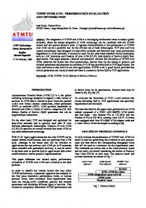
2.2 Temporal Flow Specification In order to define temporal values for the flows, the clock rate must be defined and each flow must have its own timing specifications. The clock rate is defined on the very first line of the input file by & mhertz 100 where 100 is the clock rate in Megahertz. The flow specifications are in the same format as before but with some extra timing options. There are two available timing patterns: bursty traffic and continuous traffic. The bursty pattern sends a burst of data at the maximum specified bitrate, then pauses for a relatively long period of time so not to exceed the average bitrate specified. The continuous traffic pattern simply sends a packet on a regular interval as close as possible to the bitrate specified. It is important to note that the bitrate specified is the total bit-count of the packet including header and trailer. Bitrate specified is the bitrate that the switch will see, not the rate of payload transmission. Figure 1 illustrates the input file with timing specifications. All timing options are specified below. Bursty Bursty pattern Average Bitrate Maximum Bitrate Initial delay Repeat N times
bursty avgbitrate maxbitrate inidelay repeat
%d %d %d %d
-bursty -avgbitrate 10 -maxbitrate 20 -inidelay 200 -repeat 20
Continuous pattern Bitrate Initial delay Repeat N times
continuous bitrate inidelay repeat
%d %d %d
-continuous -bitrate 5 -inidelay 20 -repeat 5
Continuous
7
MHz line must be first in the file
& mhertz 100 !TCP –srcip 128.252.0.1 –bursty –avgbitrate 4 … !IPv4 –srcip 128.252.0.2 –continuous –bitrate 4 … All flow types start with a !
When using timing, each flow MUST have a traffic type specified.
Figure 1: File format for input file with timing specifications. The first line contains the clock rate, other lines contain flow specifications with timing options specified
8
2.3 Payload Specification There are four different payload options: specify a file containing hexadecimal payload, ask for a payload that increments, ask for a pseudo-random payload, or specify the payload in the input file. Specifying the payload to come from a file simply needs the -sfile fileName option specified in the same area as the header options. The software is currently limited to not overlook line break, space, or return characters, so do not put any in the file. It should be one long string of hexadecimal characters. Specifying an incremental payload is done with -incpayload %d where the number following is the number of bytes to be payload. The payload is a 32-bit word beginning at x“11111111” and incrementing on each word. If the number of bytes is not a multiple of four, the word is simply truncated, lower bits are dropped. Specifying a pseudo-random payload is similar to the incremental payload. The flag -autopayload %d will create a pseudo-random payload of length %d bytes. It is pseudo-random because the random number generator is always seeded with the same value prior to spinning off “random” numbers. Note that this will produce the same results on the same machine and operating system, but if it is run on two different operating systems, it may produce different numbers. Specifying payload in the input file requires a line break after the last flow specification followed by hexadecimal numbers. The parser will treat anything that is not a new flow specification as payload. It should be specified in 32-bit hexadecimal numbers, each followed by a line break. The last word may be less than 32-bits, but will be read in on the byte boundary. If there is an extra hexadecimal value (an extra half-byte or nibble) it will be truncated.
2.4 Miscellaneous Flow Options With TCP and IPv4, there are additional header options that may be specified. The headers are expandable to allow for application specific information to be contained in the header instead of the payload. To include additional header options, use -ipv4options %d %08X %08X... where the first number is a decimal number specifying how many 32-bit header words are following. The remaining numbers are the header words specified in hexadecimal. Two additional options for the TCP flow are the -synfin and -tcpack options. The -synfin option is to begin the flow with a Synchronize packet and end with a Finish packet. The -tcpack option inserts acknowledgement packets in between every TCP packet of the flow.
9
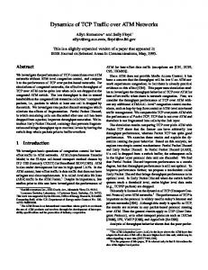
Figure 2: Input the number of flows desired.
3 Graphical User Interface To simplify the user interface to the tool, a Graphical User Interface (GUI) was written for NCHARGE [3]. From a web site, a user can click on the packet type and cut and paste the content. The flow creation process begins with step one, shown in figure Figure 2. In step one, the user must specify how many different flows are desired. The flows themselves will not necessarily be different, but they will be treated as separate flows when processed and mixed. In step two, see Figure 3, the user must select whether to mix the flows, the clock rate of the simulation/hardware, flow type, number of additional TCP and IPv4 header options, whether to include shims, and the type of traffic pattern. In step three, see Figure 4, the header options for each layer of encapsulation are displayed on the left. On the right are the payload specifications, the option to split cells on a Maximum Traffic Unit size (MTU), and timing options (if mixing was requested). Step four, see Figure 5, displays the input file used by the traffic generator. At the bottom is the option to pick which program to run the input file through. Each program uses the same parser and filters, but the output formatter is different.
10
Figure 3: Select whether to mix the flows, the clock rate of simulation/hardware, flow type, additional header options, shims, and the traffic pattern (timing or bursty).
11
Figure 4: All header options available are displayed with their default values. On the right are the payload specifications, timing options (if requested mixing), and the option to split packets based on the Maximum Traffic Unit size (MTU).
12
Figure 5: Input file is displayed and the choice of output formats is displayed. Finally, step five displays the network traffic stream created from the input file, see Figure 6.
13
Figure 6: Completely formatted cells are displayed.
14
Parser- Reads input file and calculates MTU.
Filters – Processes header options and mixes flows.
File Containing Flow Specifications
Output Formatter
AAL5 Flow
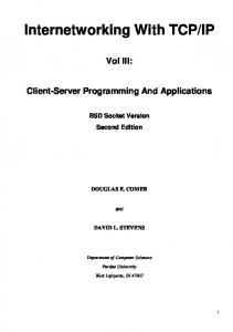
Figure 7: Structural block diagram of the packet generator.
4 Software Organization The structure of the packet generator is composed of five major blocks: flow specifications, parser, filters, output formatter, and the output. The parser reads the flow specification file, interprets the file and sends payload data, header information, and temporal specifications to the filters. The filters build the headers and mix the flows according to the specifications from the parser. Finally, the completed flow is passed to an output formatter which produces the output file in the correct format to be used for a particular testing situation.
4.1 Data Structures There are two major data structures in the packet generator: the DataBlock, and the StreamBlock. The DataBlock consists of an array of characters, a value holding the number of entries, and the size of the character array. The character array (data) holds the packet as it forms, first as only payload, then passing through filters to become a fully formatted network packet. The StreamBlock holds the options specified for the particular flow, what kind of packet the stream will be (TCP, UDP, etc.), the DataBlock associated with the flow, and a pointer to the next StreamBlock.
4.2 Parser (parser.c) Reading the input file, determining options, and formatting data for the filters is the responsibility of the parser. The Parser begins by opening the input file, looking for timing options see temporal, flow commands see basic flow, and the packet’s payload payload. The parser begins by entering a loop, reading a single line out of the input file and acting on it. Each line may have one of four purposes: temporal specification (if first line), flow specification, comment, or
15
payload. If the line is a temporal specification (marked with a ‘&’ as the firsst character of the line), the Megahertz value is stored and all StreamBlocks are marked mixable. If the line is a comment (marked with a ‘#’ symbol as the first character of the line), the parser simply goes on to the next line. If the line is a flow specification (marked with a ‘!’ as the first character of the line), a StreamBlock and a DataBlock are created. Options are then extracted from the line including flow type, header options, and temporal specifications. If the line is payload, the line is added to the DataBlock of the last StreamBlock processed. StreamBlocks are then passed to the filters, where they are manipulated to create a fully formatted network packet.
4.3 Filters There are nine filters which process a StreamBlock: TCP, UDP, IPv4, IPv6, Shim, Frame, Control Cell, Cell, and Mix filters. A StreamBlock, when fully processed, will pass through each filter in the order above. Filters look at the options (contained in the StreamBlock) and modify the DataBlock by adding header or trailer lines. As shown in Figure 8 , filters modify the DataBlock according to the options expressed in the
Figure 8: Each filter adds header or trailer information to the packet. Here, a TCP header was prepended to the payload. input file. 16
The only filter that does not manipulate the DataBlock in the above described manner is the Mix filter. The mix filter does not do anything to the DataBlock, instead it manipulates the entire list of StreamBlocks. By reading the timing options in the StreamBlock, the mix filter creates a new list of StreamBlocks, organized according to the timing options. Because there is no ‘end of stream’ marker for a multi-packet flow, the end of a flow is marked by a StreamBlock of type NONE. When the filters have processed every StreamBlock, the result is a linked list of StreamBlocks, ready to be written to a file.
17
4.4 Output Formatters There are four output formats: FAKE, RAW, SIM, and HW. The FAKE format is used in ModelSim simulations, read by testbench.vhd, a vhdl component with embedded c for reading files into the simulation. The RAW format is used by NCHARGE to inject the traffic into the FPX switch. The SIM format is also used in ModelSim simulation, but as a DO file. The HW format is for the hardware module worked on by Dave Lim. The FAKE, SIM, and HW formatters will output timing specifications as well as the stream itself. In between each cell may be a WAIT command in order to let time pass in the simulation. This is done to achieve the desired flow pattern (as opposed to sending back-to-back cells for an extended period of time). FAKE new_cell wait_100 00000902 E6000000 45000028 00000000 FF11541A 7F000001 C0A82801 138C138C 00140000 00000001 48656C6C 6F000000 00000028 E28337C6
RAW SIM !RAW force soc_mod_in 1 00000320 "force d_mod_in X""00000320""" 8A000000 run 10 45000080 force soc_mod_in 0 00000000 "force d_mod_in X""8a000000""" 40067B77 run 10 FFFF0000 "force d_mod_in X""45000080""" FF000001 run 10 FA000007 "force d_mod_in X""00000000""" 0269306E run 10 20043180 "force d_mod_in X""40067b77""" 50181000 run 10 4A270000 "force d_mod_in X""ffff0000""" C67E816B run 10 4BFBE2FB "force d_mod_in X""ff000001""" wait 690 run 10 "force d_mod_in X""fa000007""" run 10 "force d_mod_in X""0269306e""" run 10 "force d_mod_in X""20043180""" run 10 "force d_mod_in X""50181000""" run 10 "force d_mod_in X""4a270000""" run 10 "force d_mod_in X""c67e816b""" run 10
18
HW 00000000 00000000 00000320 8A000000 45000080 00000000 40067B77 FFFF0000 FF000001 FA000007 0269306E 20043180 50181000 4A270000 C67E816B 4BFBE2FB
"force d_mod_in X""4bfbe2fb""" run 10 "force d_mod_in X""00000000""" run 690
19
References [1] F. Braun, J. W. Lockwood, and M. Waldvogel, “Layered protocol wrappers for Internet packet processing in reconfigurable hardware,” in Proceedings of the Symposium on High Performance Interconnects (HotI-9), (Stanford University, CA, USA), p. 4.3, Aug. 2001. [2] F. Braun, J. W. Lockwood, and M. Waldvogel, “Layered protocol wrappers for Internet packet processing in reconfigurable hardware,” Tech. Rep. WU-CS-01-10, Washington University in Saint Louis, Department of Computer Science, June 2001. [3] D. E. T. Todd Sproull, John W. Lockwood, “Control and configuration software for a reconfigurable networking hardware platform,” in IEEE Symposium on Field-Programmable Custom Computing Machines, (FCCM), (Napa, CA), Apr. 2002.
20