Proceedings of the Second International Conference on Machine Learning and Cybernetics, Wan, 2-5 November 2003
MULTIFOCUS IMAGE FUSON IN WAVELET DOMAIN WEI-WE1 WANG’, PENG-LANG SHUI’, GUO-XIANG SONG’ I
Key Lab. For Radar Signal Processing, Xidian University, Xi’an, 710071, Shaanxi ’School of Science, Xidian University, Xi’an, 710071 Shaanxi, China
E-MAIL:
[email protected]
Abstract: How to select wavelet filters, decomposition levels and fusion schemes is of great concern for multifocus image fusion in wavelet domain. We presented a simple image fusion algorithm based on wavelet transform. By wavelet transform, an image can be represented by a low frequency approximation, which contain the average information of the image, and several high frequency details with different scales and directions, which contain the texture or edge feature of the image. For the multifocus images, there are some areas unclear in certain source images which correspond to small wavelet coefficients, and clear in other source images which correspond to large coefficients. So we simply took the coefficients with greater modulus as the final coefficients to get the fusion image, which contains more details and is clearer in visual and more convenient for image analysis and understanding. We also discussed the influence of the wavelet filters, decomposition levels and fusion schemes on the fusion results, compared wavelet based fusion with other multiresolution fusions, such as Laplacian pyramid, gradient pyramid, contrast pyramid and ratio pyramid. Some results are obtained, which are of great value for research and experiment in this field. Keywords: Image Fusion; Wavelet Transform;
1
Introduction
The purpose of image fusion is to extract and synthesize information from multiple images to get a more accurate, complete and reliable imagery description of the same scenes or targets so that the fusion image are more adaptable for the .visual characteristics of human or machine, which are useful for analysis, understanding of the image or detection, recognition or tracing for targets of interesting. When a camera is to catch several objects that are in different distances away from it, the camera could not be focused on these objects -simultaneously to get a clear image in any way. However, the camera can be focused on each object respectively to get a clear image of it. To get a clear image containing all objects, the usual method is image fusion, which has been widely applied in
some fields such as machine vision, digital camera and object recognition. Wavelet transform is a new method for multiresolution analysis, by which an image can be decomposed into the lowest approximation and several details at different scales and in different directions. The lowest approximation contains the average information and most energy of the image, while details contain edges or high frequency information at different scales and in different directions. Among the multifocus images, there are certain objects clear in some images, and some other objects clear in other images. The magnitudes of the wavelet coefficients for blurred area are less than that for clear area. So for the high frequency Coefficients (wavelet coefficients), we simply take the coefficient that is of the greatest magnitude among the multifocus images as that of the fusion image, while for the lowest approximation, we take the average as usual. Another advantage that wavelet transform has some popular transforms in image processing such as DFT and DCT is that there are affluent basis functions of different properties so that we can choose the best basis for application at hand. For image fusion, we compared some wavelet bases popular in image processing such as ‘dbN’, ’sy”’, ’coiW and ‘bi0rN.p to find that ‘bior4.4‘ performs best for most images. Additionally, the scales of wavelet transform carries out is considered, empirical results show that three level is proper either from the point of calculation or the quality of the fusion images. In image fusion, Laplacian pyramid, ratio pyramid, contrast pyramid and gradient pyramid are often used[l-4]. Although these decompositiones are all multiscale OT multiresolution transforms, they are redundant, or the decomposition coefficients are correlative and the amount of which is 113 more than original. In addition, Laplacian, ratio and contrast decomposition are isotropy. However wavelet transform is compact or the amount of data kept the same during transformation and the wavelet coefticients are in three direction, which enable us to utilize the visual characteristic of human eye to get better fusion image in
0-7803-7865-2/03/$17.00 02003 IEEE 2887
Proceedings of the Second International Conference on Machine Learning and Cybernetics, Wan, 2-5 November 2003 that h u m eye has different resolution for high frequency components in different direction. Comparison between fusion in wavelet domain and that with other multiresolution methods such as Laplacian pyramid, ration pyramid, contrast pyramid and gradient pyramid, shows that fusion with Laplacian pyramid and ratio pyramid is comparable to that with ‘bio197’, but calculations of the latter is far less. .
2 2.1
3.1
2-D DWT
If an image is transformed into L levels, we will get (3L+1) subbands, one approximation subband or baseband C, of low frequency and 3L subbands oh,D’, and od of high frequency. Let f ( x , y ) be an original image, denoted by C, 2-D DWT can be performed as follows:
IC,+l = HC,H’ Or+,= HCjG’
(j
= O,l,...,J-l),
= GC,G’ where h,v,d represents horizontal, vertical and diagonal respectively. H‘and G‘ is conjugate transpose of H and G.‘J is the decomposition level. Reconstsuction formula is C1-1. = H’C,H i GD;H HDJG GDpG
+
+
( j = J,J - 1;..,1). 2.2
horizontal,
3
Image fusion in wavelet domain
D$, = GC,H’
A W ~ ( k , I ) , B W ~ ( k , I ) , F W ~ ( kbe, I )the wavelet coescients of A, B and F. R=H,V, D, represent Let
A simple fusion rule in wavelet domain
Let A and B be two source images, F be the fusion image. The basic steps for fusion are: Step 1) perform 2-D DWT on A and B respectively to get wavelet pyramid of each; Step 2) fusion each subbands from A and B to get subbands of F; Step 3) reconstruct to get F. The fusion rule is key to the fusion quality. For simplicity and good fusion result, we propose the following simple rule: Take the average of the baseband from A and B as the baseband of F; For high frequency components, we simply take the coefficient that is of the greatest magnitude among the multifocus images as that of the fusion image.
vertical,
and
diagonal.
Image fusion experiment ehoiee of wavelet filters, decomposition level and fusion rule
We adopt the fusion method described in section 2.2. The source image is transformed into 3 level. We first compare the fusion results using some orthogonal wavelets with different vanishing moments that are usually used in image processing. The results are listed in table 1, where. ‘dbN’ represents compact supported orthogonal waw!it with N vanishing moments in [6], ’sy”’ represents the least asymmetric orthogonal wavelet with N vanishing moments in [6],and ‘coifW represents the wavelet filters that both scaling function and wavelet function have N vanishing moments constructed by Coifinan. It can be seen there is little effect of the vanishing moment on the fusion results and ‘db4’ performs best. As orthogonal wavelets are asymmetric except ‘haar’, which results phase distortion, symmetric biorthogonal wavelets with increasing vanishing moments are constructed in [6]. Among them ‘bior2.2’ and ‘bior4.4’ or ‘bior97’ are more popular in image processing. The fusion results using these filters are listed in table 2. Again, there is no regular effect of the vanishing moment on the fusion results. Obviously, ‘bior4.4‘ is the best. In order to assess the effect of decomposition level on the fusion result, we decompose the source images into one, two, three and four levels using ‘bior4.4’. The fusion results are listed in table 3. It can be seen that the fusion quality improves as the number of decomposition level increases, but when the number of decomposition level arrives at certain level, 3 level in this case, the quality becomes worse. In addition, calculation increases if the number of decomposition lever increases. Then we compare the simple fusion in section 2.2 with the fusion algorithm in [5], which is based on the local property of the image. The results are given in table 4. Obviously, the simple fusion is better. Through comparisons above, it can be concluded that among usually used orthogonal and biorthogonal wavelets, the simple fusion with ‘bior4.4’ performs the best for image fusion.
2880
Proceedings of the Second International Conference on Machine Learning and Cybemetics, Wan, 2-5 November 2003 3.2
Compare fnsion in wavelet domain with other multiresolution methods
qnantity. References
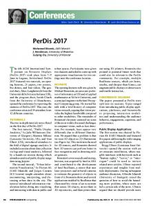
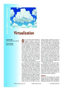
By comparison above, it can be seen that the simple fusion with ’bior4.4’ is a good choice for fusion in wavelet domain. The source images, reference image and fusion image using ‘bior4.4‘ are shown in Figure I. For other multiresolution methods, we compared the simple point based fusion with the complex local neighbor based fusion and found that the latter is better, so in Table 5, we give the best result in wavelet domain and the best results with other multiresolution methods. Additionally, we gave the results of simple fusion in space domain. ‘Max’, ’Min’ and ’Ave’ respectively represent taking maximum, “ n u n and average value of gray value of pixels of the source images. Obviously, the simple fusion with ’biofl7’ performs best, followed by fusion based on Laplacian pyramid and ratio pyramid, but the latter costs more calculations. 4
Conclusion
This paper presents a simple image fusion method based on wavelet transform. It is simple and cost little calculation. Experimentative results show that the simple fusion based on ’bior4.4’ is usually the best either in visual or in
[I] Toet A. Hierarchical image fusion. Machine Vision and Applications. 3(1): 1-11, Jan.,1990 [2] Toet A. Multiscale contrast enhancement with application to image fusion. Optical Engineering. 3 l(5): 1026-103I, May, 1992 [3] Toet A. van h y v e n L J, Valeton J M. Merging thermal and visual images by a contrast pyramid. Optical Engineering. 28(7):789-792, July, 1989 [4] Toet A. Image fusion by a ratio of low-pass pyramid. Pattern Recognition Letters. 9(4):245-253, April, 1989 [5] Liu Guixi. Study on multisensor image fusion. A dissertation for Ph.D degree of Xidian University. 2001 [61 Daubechies I. Ten Lectures on Wavelets. CBMS Conference Series in Applied Mathematics, SIAM, Philadelphia, 1992 171 Li Shutao, Wang Yaonan and Gong Lizbnan. Choice for the best wavelet decomposition level in multifocus image fusion. System engineer and eleceonic technology. 24(6):45-48, Jnne,2002
Ta
avelets
relets Biorthogonal wavelets ‘Bior2.2’ ‘Bior4.4’ or ’biOfl7’ ‘Bior5.5’ ‘Bior6.8’
PSNR 27.5846 33.8855 28.5657 29.0250
2889
RMSE
’
10.6490 5.1554 9.5116 9.0218
Proceedings of the Second International Conference on Machine Learning and Cybernedcs,m a n , 2-5 November 2003 Table 3. Decomposition levels
.
Fusion methods Simple fusion Fusion based on local property
PSNR
I
RMSE
PSNR 33.8855 28.2327
I I I
Table 5. CO
RMSE 5.1554 9.883
elution methods
(c) reference image Figurel. fusion image using the simple fusion method and 'bior4.4' with 3 level decomposition.(a)soue image A, (b)source image B, (c)reference image, (d)fusion image
2890