Special Feature:
Next-generation Core Network
Multilayer Service Network Architecture for Next-generation Core Network Takashi Kurimoto†, Hisashi Kojima, Ichiro Inoue, and Shigeo Urushidani Abstract A new multilayer service network architecture is proposed. In this network, which consists of edge and core nodes, an optical path is autonomously established between edge nodes, and traffic is transferred directly to enable a large amount of traffic to be carried. This technique is called “optical path cutthrough control”. An integration technique called multilayer correlation is also described. This function enables dynamic provision and restoration of the connectivity of multiple layers working in concert with each network layer. A multilayer service network will be shared by multiple service networks having different address spaces and different operating policies.
1. Introduction Today, the amount of backbone traffic is exploding as a result of the rapid increase in broadband access, new applications, and new services. The number of broadband access users in Japan increased by 33.4% compared with the previous year, and at the end of 2003 the total number of broadband access users was † NTT Network Service Systems Laboratories Musashino-shi, 180-8585 Japan E-mail:
[email protected]
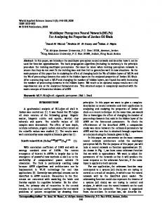
26 million [1]. The backbone network is expected to carry a tremendous amount of traffic from this huge number of broadband access users. In the near future, routers that can handle several tens of terabits per second will be required for service providers to provide broadband communication services. It looks difficult for routers to reach the level of 10 Tbit/s in a few years, although the implementation technology of router systems is progressing. The relationship between router performance and the commercial introduction date is shown in Fig. 1. The rate of increase in router performance has slowed recent-
1T 1. Cisco GSR12008 (20 G) 2. Cisco GSR12016 (40 G) 3. Juniper M40 (20 G) 4. Juniper M160 (80 G) 5. Cisco GSR12416 (160 G) 6. NEC CX5220 (160 G) 7. AVICI TSR (400 G) 8. Juniper T640 (320 G) 9. Vivace Viva5100 (320 G) 10. Hitachi GR-4000 (160 G) 11. Procket PRO/8812 (480 G) 12. Cisco CRS-1 (640 G)
System capacity (bit/s)
12. 11.
7.
8. 9. 10.
5. 6.
100 G 4. 2. 1. 3. 10 G
98
99
00
01
02
03
04
05 Year
Fig. 1. Router performance versus commercial introduction date.
30
NTT Technical Review
Tec h n o l o g ies
ly as a result of technical problems. Power consumption is one important issue. In the current router system, about 2 kW of power is consumed per 100 Gbit/s, which indicates that 200 kW will be consumed in a 10-Tbit/s router. This is equivalent to the power consumption of five hundred ordinary homes, so it is difficult to make such a router. To accommodate the large amount of IP (Internet protocol) traffic, we need a function for handling cooperation between packet technology (such as IP routers) and optical technology (such as wavelength division multiplexing (WDM) and optical cross connects (OXCs)). An optical network layer can transmit a lot of data economically, but it cannot handle packet switching. Integrating the optical and IP network layers should enable a large amount of IP traffic to be carried. Technologies for controlling equipment in both network layers, such as GMPLS (generalized multiprotocol label switching) [2], [3] and OIF (Optical Internetworking Forum) [4] signaling and routing technologies, have been studied. GMPLS is a path control protocol for multiple network layers including IP and optical networks. In this article, we propose a multilayer service network architecture based on GMPLS [5], [6] to carry a large amount of traffic.
(1) Optical path cut-through Service network traffic is transferred by an optical path.
2. Multilayer service network Figure 2 shows the network architecture for a multilayer service network (MLSN). There are various service networks and a multilayer service network. Service networks provide various kinds of service (i.e., IP networks) and are accommodated by the MLSN. User traffic of the service networks is carried across the MLSN, which consists of edge nodes and core nodes. An edge node has a multilayer correlation function and controls the optical path automatically according to the network management policy. To enable a large amount of traffic to be carried, a new optical path is automatically established between a pair of edge nodes over the MLSN and traffic is transferred directly. We call this “optical path cutthrough control”. The optical path is established using GMPLS technology. However, GMPLS is still not mature in terms of interoperability and node control capability, so we must supplement it. Furthermore, integration technology is expected to allow dynamic provision and restoration of the connectivity of multiple layers by working in concert with each network layer. We call our integration technology a multilayer correlation function. However, there has not been enough study of the multilayer correlation function to operate multilayer paths considering both optical and IP network information. In addition, an
(2) Multilayer correlation Optical path establishment is triggered considering multilayer network information.
(3) Accommodation of various service networks Various service networks are constructed upon the common core network.
Service control and operation
Server APL
APL: application OSS: operations support system
OSS
Core
Service network #1
Service network #1
Edge Service network #n
Service network
Optic
al pa
Edge
th cu
t-thro
ugh
Multilayer service network
Service network #n
Service network
Fig. 2. Network architecture for multilayer service network.
Vol. 2 No. 11 Nov. 2004
31
Special Feature
optical network should be shared by multiple service networks to reduce the network cost, but there has not been enough study of how to maintain the operating policies among multiple service networks. 2.1 Optical path cut-through control If there is enough traffic between a certain pair of routers and the traffic is transiting a router, then the IP forwarding performance of the router is not fully utilized by the transit traffic. To avoid such wastage, a new optical path is established between the pair of routers, and traffic is transferred directly. On the other hand, if there is not enough traffic between a certain pair of routers and the traffic is transferred directly, then the optical path is underutilized. In this case, the optical path between the pair of routers is deleted and traffic travels via other routers. Since GMPLS is not yet mature, its protocol should be extended. For example, when the router connects an optical path directly to another router using GMPLS protocols, the router should be configured to forward packets via the newly established path. Therefore, extension for transferring parameters is needed to exchange information with another router. (OSPF (open shortest path first) protocol configuration parameters, such as IP address and link cost, are transferred for setting up the OSPF protocol on the interface of the newly generated optical path. The OSPF neighbor on the optical path is correctly set up using this information and IP traffic is forwarded through the optical path.) GMPLS standardization and the interoperability testing among multi-vendor systems are being promoted in NTT Network Service Systems Laboratories. These standardization activities are described in the second feature article in this issue [7]. 2.2 Multilayer correlation function A multilayer correlation function is required to manage the dynamic optical path provisioning and restoration, considering both optical and service-network information. For example, a set of optical paths is simultaneously established dynamically to optimize the network topology and carry the traffic efficiently. In other cases, redundant optical paths are dynamically established to carry the important traffic provided by the service network. Therefore, optical paths are established through close correlation with service network operations. Note that the existing IP network is constructed based on a fixed topology, while in MLSN, the topology is configured dynamically. 32
Our architecture has a multilayer correlation function that can be logically separated from a node system. Since quick introduction of new services and flexible addition of some different features are required, a network operator wants to flexibly customize the optical path operating policy and make its own control policy or algorithm. Therefore, we started promoting the standardization of interfaces among the multilayer correlation function and node systems. This scheme allows flexible optical path control to be achieved corresponding to each service-network operating policy. These multilayer correlation functions are described in the third feature article in this issue [8]. 2.3 Multiple network accommodation Generally, a carrier provides various network services and these services are provided by various service networks, which are constructed upon a common core network. For example, there are different layer networks (such as IP and Ethernet networks) and different type of services (such as IP-VPN (Internet protocol virtual private network) and best-effort IP services) and these can be accommodated in a common optical network. To enable several service networks to be accommodated, the resources of an optical network must be managed by each service network independently. Figure 3 shows the autonomous control of the service network. There are four processes in IP service-network management: (1) planning of facility deployment and management, (2) optical path establishment and management, (3) router configuration, and (4) IP routing management. In the MLSN, the multilayer-correlation-function controls two operations autonomously: path establishment/deletion to optimize the service network and the setup of IP routers to forward IP traffic through the established optical path or detour it around a deleted optical path. In addition, the address spaces of service networks should be separated from the address space of the GMPLS control plane and also separated from each other because service-network address spaces will be managed by the different operators of each service network. However, GMPLS has not been studied enough to be used in this environment. Therefore, to accommodate several service networks, the multilayer correlation function also performs address space separation/mapping in the MLSN. 2.4 Control plane architecture Figure 4 shows an example network architecture NTT Technical Review
Special Feature
Planning of facilities (e.g., fiber)
Autonomous control
GMPLS technique
Optical path establishment and management
IP router configuration (e.g., IP address)
Correlation function
Autonomous control
Autonomous IP dynamic routing
MLSN Current system
Fig. 3. Outline of IP service network operation.
Multilayer correlation function
Edge 2 Edge 1
Core 2 Edge 3 GMPLS control plane
Edge 4
Core 1
Core 3 Edge 5
Edge 1
Edge 2
Edge 3 Layer-3 network
Edge 4
Edge 5 Layer-2 network
Edge 6
Edge 7 Core 1
Core 2 Layer-1 network Core 3 Common optical network
Multilayer service network
Fig. 4. Example network architecture for multilayer service network.
Vol. 2 No. 11 Nov. 2004
33
Special Feature
for MLSN. In this figure, the network consists of three service network layers and the GMPLS control plane. Layer-1 is the physical layer (e.g., optical networks), layer-2 is the data link layer (e.g., an Ethernet network), and layer-3 is the network layer (e.g., an IP network). Each service network can be managed separately. MLSN consists of edge and core nodes. Edge nodes of a service network are connected to core nodes of the common optical network. Edge and core nodes both have a GMPLS control function, which manages path establishment/deletion across the optical network. The edge node has a network-controlinstance corresponding to each service-network layer. Each network control instance sends and receives network resource information about each service network, such as network topology, traffic amount, quality of service, and residual bandwidth. Therefore, an edge node can collect network information about both the GMPLS-controlled network and service networks to achieve multilayer correlation. The multilayer correlation function can take into account all the network resource information together. It can trigger optical path establishment considering resource information about both networks. For example, a dynamic optical path is established according to the traffic statistics of the IP service network. There are two ways to implement the multilayer correlation function: the autonomous distributed form and the centralized form. In the autonomous distributed form, each node collects network information about all network layers and controls the optical paths in a distributed manner. On the other hand, in the centralized form, the optical path is managed by the centralized server. The multilayer correlation function is shown in the centralized form in Fig. 4. 3. Service network accommodation 3.1 L1VPN The layer-1 virtual private network technology (L1VPN) [9] provides service networks that are accommodated in the MLSN. L1VPN provides the advanced management capability to allocate the layer-1 path to each service-network in accordance with its own policy. The goal of L1VPN is to let each service-network operator manage the optical network resources independently of other service-network management as if they belonged to its own optical network. Figure 5 outlines the resource allocation among several service networks. Physical facilities are allo34
All network resources
Service network #2 Fixed resources Allocation
Shared resources
Allocation Service network #1 Fixed resources
Fig. 5. Outline of resource allocation among several service networks.
cated by either fixed or shared allocation. Fixed allocation means that physical facilities are occupied by only a specific service network, while shared allocation means that they are allocated to any service networks dynamically. Shared allocation facilities are utilized for fault recovery or dynamic optical path cut-through for efficient data transfer. These dynamic optical path allocations are operated according to the kind of service network or service-network operation policy. 3.2 IP network In this section, we focus on IP network stability when the IP service network is accommodated in the MLSN. The problem is that IP routing becomes unstable after dynamic optical path establishment/ deletion. When the IP network topology is changed by adding new optical paths or deleting optical paths in the current IP network, all routers exchange new network topology information and re-calculate the best route for packet forwarding. Therefore, frequent dynamic optical path establishment/deletion leads to unstable IP packet forwarding. The MLSN requires a mechanism that makes the service network stable during dynamic optical path establishment/deletion. We propose a virtual link method as one solution to prevent unstable IP packet forwarding. In this method, a layer-2 virtual link (e.g., an MPLS path) is used as a link carrying IP traffic. Figure 6 shows the optical path cut-through operation with the virtual link method. Routers are connected by virtual links, NTT Technical Review
Special Feature
Physical equipment and virtual links Edge 2
Edge 2 Y
Y Edge 1
Edge 1
Edge 3
Edge 3 X
X
Z
Z
Edge 2
IP routing topology Edge 1
Edge 2 Edge 1
Edge 3
Virtual link
Optical path
Edge 3
Layer-2 switching node
Fig. 6. Optical path cut-through with virtual links.
which they use to manage the routing calculation. These virtual links are controlled by the GMPLS mechanism. When new optical paths are established, virtual links are re-routed via them simultaneously. During the dynamic optical path establishment operation, the IP routing topology is not changed, so a router does not need to re-calculate the IP forwarding table, which prevents IP packet forwarding becoming unstable. Moreover, the layer-2 switching function can be integrated into the router, so the number of nodes can be reduced. 4. Summary We proposed a multilayer service network architecture. This network consists of edge and core nodes, and several service networks can be accommodated in a common optical network. In this network, optical paths are controlled in an integrated manner. And an optical path is automatically established between nodes to carry large amounts of traffic and multilayer correlation allows dynamic provision and restoration of the connectivity of multiple layers working in concert with each network layer. In addition, multiple
Vol. 2 No. 11 Nov. 2004
service networks, which have different address spaces and different operating policies, can be accommodated in the multilayer service network. References [1] [2] [3]
[4] [5]
[6]
[7]
[8]
[9]
http://www.johotsusintokei.soumu.go.jp/whitepaper/ja/h16/index.html L. Berger, “Generalized multi-protocol label switching (GMPLS) signaling functional description,” RFC3471, IETF 2003. L. Berger, “Generalized multi-protocol label switching (GMPLS) signaling resource reservation protocol-traffic engineering (RSVP-TE) extensions,” RFC3473, IETF 2003. “User network interface (UNI) 1.0 signaling specification, release 2,” OIF, Feb. 27 2004. I. Inoue, T. Kurimoto, H. Kojima, and S. Urushidani, “Next generation core network architecture: multilayer service network architecture,” NTT Technical Journal, Vol. 15, No. 12, pp. 52-56, 2003 (in Japanese). T. Kurimoto, T. Miyamura, M. Aoki, I. Inoue, N. Matsuura, H. Kojima, and S. Urushidani, “A proposal of multilayer service network architecture,” Technical Report Sep. 2004, Technical Group on Photonic Network, IEICE, 2003. T. Ohba, T. Takeda, K. Shimizu, I. Inoue, and S. Urushidani, “Globalization of Next-generation Core Network Control Technology,” NTT Technical Review, Vol. 2, No. 11, pp. 37–41, 2004. T. Miyamura, R. Hayashi, A. Misawa, and S. Urushidani, “Multilayer Coordination Technologies for Next-generation Core Networking,” NTT Technical Review, Vol. 2, No. 11, pp. 42–47, 2004. T. Takeda, H. Kojima, and I. Inoue, “Optical VPN architecture and mechanisms,” APCC2003, Sep. 2003.
35
Special Feature
36
Takashi Kurimoto
Ichiro Inoue
Research Engineer, Network System Innovation Project, NTT Network Service Systems Laboratories. He received the B.E. and M.E. degrees in applied physics from Tokyo Institute of Technology, Tokyo in 1992 and 1994, respectively. He joined NTT in 1994 and has been researching switching technology for high-speed computer networks and multimedia communication networks. He received a switching system research award from the Institute of Electronics, Information and Communication Engineers (IEICE) in 1996.
Senior Research Engineer, Supervisor, Network System Innovation Project, NTT Network Service Systems Laboratories. He received the M.E. degree in electrical engineering from the University of Tokyo, Tokyo in 1990. He joined NTT the same year. Since then, his research interests have included telecommunication protocols such as IP and ATM. He has been active in standardization such as ISO/ISC (as a national committee member), ITU-T, and IETF. He was a visiting researcher at Columbia University, USA in 1995.
Hisashi Kojima
Shigeo Urushidani
Engineer, Network System Innovation Project, NTT Network Service Systems Laboratories. He received the M.E. degree in electronics, information and communication engineering from Waseda University, Tokyo in 1999. He joined NTT the same year and has been studying IP network and IP optical network architectures. He is a member of IEICE.
Senior Manager and Research Group Leader, NTT Network Service Systems Laboratories. He received the B.E. degree in electrical engineering and the M.E. degree in electronic engineering from Kobe University, Kobe, Hyogo in 1983 and 1985, respectively. He received the Ph.D. degree in electronic engineering from the University of Tokyo, Tokyo in 2002. In 1985, he joined NTT, where he engaged in R&D of ATM switching systems and optical switching systems. In 1992, he moved to NTT Network Engineering Headquarters and began working on strategic planning and construction of intelligent, broadband, public communication networks. He is currently involved in R&D of next-generation IP optical networks at NTT Network Service Systems Laboratories. He is also a Visiting Professor at the National Institute of Informatics (NII). He received the excellent paper award (1988) and the young engineering award (1990) from IEICE. He is a member of IEEE.
NTT Technical Review