Multilevel Modelling Software Development Hector A. Duran-Limon Information Department, CUCEA, University of Guadalajara, Mexico
[email protected]
Abstract Different from other engineering areas, the level of reuse in software engineering is very low. Also, developing large-scale applications which involve thousands of software elements such as classes and thousands of interactions among them is a complex and error-prone task. Industry currently lacks modelling practices and modelling tool support to tackle these issues. Model driven development (MDD) has emerged as an approach to diminishing software development complexity. We claim that models alone are not enough to tackle low reuse and complexity. Our contribution is a multilevel modelling development (MMD) framework whereby models are defined at different abstraction levels. A modelling level is constructed out by assembling software elements defined at the adjacent lower-level. MMD effectively diminish development complexity and facilitates large-scale reuse.
1. Introduction It is striking to notice that most software systems are still constructed from scratch, different from other engineering areas, the level of reuse in software engineering is very low. Object-oriented systems failed in their promise for creating a market place for class libraries. The main reason this happened is twofold. Firstly, classes do not support plug-and-play. That is, they are not ready to use as classes have to be compiled. The major problem here is that additional effort has to be paid to compile and link the library to the application. Moreover, the compilation process is often not transparent, requiring also an extra effort to deal with platform dependencies. Secondly, encapsulation is broken as class libraries are typically distributed in source form. Thus, programmers are immediately tempted to read and modify the code to make it more suitable for their applications. Importantly, software components are emerging as an approach that promises to reach the level of reuse that object-oriented systems could not achieve. A software component is “a unit of composition with contractually specified interfaces and explicit context dependencies only. A software
component can be deployed independently and is subject to composition by third parties” [1]. A software component is essentially a binary which is able to be deployed in different environments and can be composed with third party developed components. In contrast to classes, software components are ready to be plugged in and their binary form avoids encapsulation to be broken. However, there are still several issues that have to be tackled for component software to succeed. Component specifications need to be precise and complete. Formal specifications such as algebraic expressions [2] and preand post-conditions [1] can be used to define functional behaviour. However, the definition of non-functional behaviour such as resource requirements is still an open issue. Component classification is required to create repositories where component can be searched and retrieved. There is of course a close relation between component specification and the classification method. Also, there is a lack of support for guided architectural design involving software composition. That is, tool support is required to detect design errors which for example may involve incompatibilities in the design pattern that components assume. Another important problem is the following. Largescale applications can involve thousands of software elements such as classes and thousands of interactions among them. Hence, developing such kind of applications is a complex and error-prone task. Industry currently lacks modelling practices and modelling tool support to tackle this issue. Software architecture [3] is a discipline that is emerging as an approach able to reach higher abstraction levels for architecture design. This approach alleviates the software development complexity and makes this process less error-prone. Model driven development (MDD) [4] is also contributing to diminishing software development complexity. MDD focuses on raising the abstraction level at the level of models and encourages model reuse. Software architecture focuses on methodologies that guide the architecture design and also is concerned with introducing architecture specifications into models. Complementary to this, MDD focuses on other aspects such as model reuse and model transformation. Open issues in MDD include model integration whereby
different domain specific models can be integrated into a single model. There is a synergy among software architecture, MDD, and software components which has not been investigated sufficiently. The synergy promotes defining models of software architectures in terms of component types which can be mapped and transformed into software components. In this paper we present the multilevel modelling development (MMD) framework. The main contribution of the paper is defining a new software construction paradigm which defines various levels of abstraction for both software composition and software reuse. The structure of the paper is as follows. The MMD framework is presented in section 2. Section 3 elaborates on how the framework is used to build software systems. The prototype implementation is presented in section 4. Finally, ongoing work and concluding remarks are drawn in section 5.
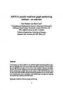
Crucially, in order to achieve composition both at each modelling level and across modelling levels it is important to ensure pattern design compatibility among the composed elements. For example, a synchronous communication pattern is incompatible with an asynchronous communication architecture. Every single software element assumes at least one design pattern i.e. the communication pattern. As shown in figure 1, the MMD framework includes a number of modelling levels namely, software architecture system, software product line (SPL) families, component framework (CF)s families and component type hierarchies. Each level has associated a repository whereby models are stored and retrieved. The use of repositories at multiple levels enables large-scale reuse and composition. This approach also makes reuse and composition flexible as both of them can be carried out at various levels of granularity.
2. The MMD Framework We argue that models alone, without a principled manner to use them, are not enough to build complex and robust software systems. Models can be very complex when representing large-scale applications. UML’s class diagrams, for example, can be extremely difficult to understand when thousands of classes are involved. Notably, architecture description languages (ADLs) [5] are modelling notations which provide a higher abstraction level for specifying software architectures. However, ADLs themselves do not prescribe how can architectural designs at various granularities be composed or classified. Hence, an ad hoc approach is employed which only results on a best effort practice to tackle complexity issues. Hence, it is not guaranteed that a high-level of reuse and composition can be achieved. It is required the ability to define models at various abstraction levels whereby each level comprises a different amount of architectural details. Each modelling level represents a different abstraction level for both software composition and software reuse. This is a bottom-up approach whereby an upper-level is constructed from its adjacent lower-level. At each modelling level, software elements are classified into families. Many aspects can be taken into account to perform this classification such as functionality, domain, etc. However, one of the most important aspects involves the design patterns a software element assumes. A design pattern [6] (also called architectural pattern or architectural style) is a proved solution to a specific problem and represents an architecture design.
SW Architecture System
SW product line families
Component Framework Families
Component Type hierarchies
Figure 1. The MMD Framework At the top level, coarser-grained architecture designs are composed to build the entire software application. At this level, composition of software architecture product lines (SPLs) is performed. A SPL is “a set of softwareintensive systems sharing a common, managed set of features that satisfy the specific needs of a particular market segment or mission and that are developed from a common set of core assets in a prescribed way” [3]. Basically, a SPL comprises a disciplined, strategic reuse of assets which are targeted to a specific market segment. SPLs are envisioned as software factories where a single
software architecture is reused to develop several software products. For example, an application may be formed by a user interface SPL, a middleware SPL, and a data system SPL. A SPL is oriented towards a particular domain such as middleware. However, SPLs also target specific market segments, e.g., a point of sale system for pharmacies. Therefore, there may be some applications that are directly constructed from a single SPL, thus, not requiring performing SPL composition. A level below are placed (SPLs) families. At this modelling level, a SPL is built up from a set of component frameworks (CFs). A component framework (CF) “is a set of interfaces and rules that govern the interaction of components ‘plugged into’ them” [1]. Essentially, CFs are partial implementations involving a set of components that represent a reusable architectural designs. Such a design is typically focused on a particular domain. Hence, CF assembling is performed at this level. Architectural pattern compatibility is checked among the assembled CFs. The families produced at this level are classified by both design pattern and target domain. CF families are defined at the below modelling level. At this modelling level components and connectors are composed to construct a CF. Components represent a computation unit whereas connectors represent interactions among components. Architectural pattern compatibility is checked among the assembled components. CFs are classified into families by the design pattern(s) they implement. Hence, the family branches determine compatibility among CFs. Above the bottom layer, where software components are placed, we have component and connector type models. The issues mentioned below about component types also apply to connector types. Component types are classified by type hierarchies. Component types are divided into platform independent and platform dependent component types. A component type can be mapped to one or more software components.
3. The MMD Framework at Work A visual modelling tool is used to defining the models and enabling visual assembly of software elements. The tool also guides the software architect in the development process. This guide includes an engine for storing, searching and retrieving from a repository, software elements such as components and CFs. The tool must ensure that the retrieved elements are of suitable types and implement or assume the adequate design pattern(s). Several roles are involved in the MMD process. The system architect is in charge of analyzing system requirements and devising a system partitioning into SPLs. At this level, interoperability of SPLs must be
guaranteed. The system architect also defines the requirements for each SPL. According to the requirements passed by the system architect, the SPL architect is in charge of either refining an SPL obtained from the tool’s repository or creating a new SPL. For the latter, the SPL is architected in terms of a set of CFs. In both cases, the variation points of each product line are given a specific value. Also, the requirements for each CF contained in a SPL are generated. The CF architect takes the requirements passed by the SPL architect and is in charge of both designing and implementing the framework if not contained in the repository. Otherwise, the CF is refined as CFs are typically partial implementations. In addition, the CF architect defines the component types required either for a new CF or for a refined CF. The software component developer is in charge of constructing software components out of component type specifications. The tool can help in generating part of the component code. The deployment descriptions are also defined. Classification information is included in these descriptions for the integration of the component into the system’s repository. Alternatively, the software component developer can purchase the required components if they can be obtained in the market place. Finally, the software component deployer is responsible for specifying the deployment of components to nodes. This specification is interpreted by the tool, hence, automating the allocation of software components. Receive requirements from upper-level Define architecture design
Pass requirements to lower-level
Receive SW elements from lower-level
Deliver produced SW elements to upper-level
Test produced SW elements
Assemble SW elements
Figure 2. The Software life-cycle in the MMD Framework At each level, the software elements required by the upper-level can alternatively be purchased from the software market if available. This of course have some advantages such as reduction in costs and increased
robustness. The disadvantage of this approach when taken to an extreme is the loss of competitiveness. Each architect is involved in the software life-cycle shown in figure 2. Requirements are first received from the above modelling level. Based on this, the architect generates a design which in turn involves a number of requirements that are passed to the immediate lower modelling level. As a result, the architect receives one or more software elements meeting the passed requirements. The received software elements are evaluated and further requirements can be generated at this stage to best meet the architecture design. In consequence, the architect proceeds to assemble the software elements at her modelling level. The assembling process ends up in producing one or more software elements which are tested before being passed to the upper modelling level. In case the tests carried out are not successful, the architect goes back to one of the following phases: design, passing requirements to the lower-level or assembling software elements.
architecture specification. Further tool support is required to verify semantic correctness. The tool allows us to define component types, connector types and interface types. A component type involves a module unit associated with one or more interface types. The interfaces can be either provided or required. We use the CORBA Component Model (CCM) [10] notation to represent them as facets and receptacles, respectively. Connector types, which define point to point interaction, must define two interface types, a facet and a receptacle. Interface types include a set of operation names associated with a return type and I/O parameter types. Defined types are then used to build an architecture design. Composite components and connectors can be specified. Composition is recursive, thus, n levels for composition can be achieved.
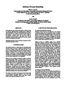
4. Implementation We have implemented an initial prototype of a visual editor tool in Java as a plugin of Eclipse [7]. The Eclipse’s graphical editing framework (GEF) is also used. The modelling notation used by the editor is Xelha [8], an ADL for distributed multimedia systems. The visual tool allows for visual modelling of a system architecture, as shown in figure 3. The system’s graphical representation is automatically transformed to a textual representation expressed in an XML document. We are using an XML-based approach whereby Xelha’s grammar is defined by XML schemas. The grammar of Xelha is partitioned into four different schemas: body, components, connectors, and interfaces. The body schema defines the general structure of an architecture specification. Such a specification is made in terms of components, connectors, interfaces and configurations. The former three have a schema associated. Configurations define how components and connectors are interconnected. Configurations are defined within the body, components and connector schemas as both components and connectors can be composite. The advantage of using XML schemas is that the ADL’s grammar can be easily changed and extended without the need to perform major changes to the tool. For example, if we need to change the component’s grammar it would suffice to replace the component schema with the new grammar. Within the editor, a model can be validated by using the XML parser XercesJ [36]. Hence, we can verify the syntax correctness of an
Figure 3. Visual editor tool for software architecture design
5. Concluding remarks We have presented a novel approach for improving practices in software development. MMD is a framework which allows the software architect to abstract away architecture details at different modelling levels, thus, being able to dramatically reduce complexity for large-
scale system development. The approach also encourages and facilitates large-scale reuse. At the finest-granularity level we have software component reuse, larger reuse is achieved through CFs and SPLs where whole architecture designs are reused. Other benefits include considerably reducing time-to-market and costs, and increasing robustness. Also, development time estimation can more accurately be calculated as it is clear from an early design stage the complete software architecture and, in consequence, the precise requirements for the missing software elements are known. Hierarchical composition when supported by ADLs, can only be achieved in an ad hoc manner. In contrast, our framework defines structured and well-defined composition levels. Our approach is different from the Meta-Object Facility (MOF) [11] where different levels of meta-modelling are defined. A meta-model describes modelling languages, e.g. their syntax. In contrast, in MDD a modelling level does not define any syntax but units of composition that can be used at the next modelling level. On going work concerns developing a classification and retrieval system for both component types and software components. A repository for both CFs and SPLs altogether with a classification and retrieval system is also underway. Support for model transformation will also be included. In particular, the tool will be provided with the ability to transform a platform independent model to platform dependent models which in turn will be transformed into source code. We are aiming to support the integration of other domain specific languages into the system by using metamodelling [11]. Validation of semantic correctness will be achieved at each modelling level by the use of formal methods such as Petri nets. Finally, we are looking at the issue of providing support for quality of service (QoS) modelling. A task model [8] is used to model QoS properties. Such visual models are then transformed by the tool to a specification of the resource system configuration. As a result of interpreting these specifications, the tool generates code that implements the resource management mechanisms that enforce the establishment and maintenance of QoS contracts.
References [1] Szyperski, C. (2002). Component Software: Beyond Object-Oriented Programming. Second Edition. Harlow, England, Adison-Wesley.
[2] I. Van Horebeek and J. Lewi. Algebraic Specifications in Software Engineering: An Introduction. Springer-Verlag, Berlin, 1989. [3] Bass, L., P. Clements, et al. (2003). Software Architecture in Practice, Addison Wesley. [4] Selic, B. Model-Driven Development: Its Essence and Opportunities Ninth IEEE International Symposium on Object and Component-Oriented Real-Time Distributed Computing (ISORC), 2006. [5] Medvidovic, N. and R. N. Taylor (2000). “A Classification and Comparison Framework for Software Architecture Description Languages”. IEEE Trans. Software Eng. 26 (1). [6] Gamma, E. R. Helm, et al. (1995). Design patterns, Elements of Object-Oriented Software, Adison-Wesley. [7] Steve Holzner. Eclipse: Programming Java Applications. O’Reilly. 2004. [8] Duran-Limon, H. A. and G. S. Blari (2004). “QoS Management Specification Support for Multimedia Middleware.” The Journal of Systems and Software. Elsevier Science Publisher. 72(1): 1-23. [9] XML parser: http://xml.apache.org/xerces-j/ [10] OMG. “CORBA Component Model”. 2006. From http://www.omg.org [11] OMG. CORBA Components Model – FTF drafts on MOF chapter. Needham, MA USA, Object Management Group. 1999.