Multilevel Routing Protocol for Energy Optimization in Wireless Sensor Networks Hamza Fahim1 , Nadeem Javaid1,*, Zahoor Ali Khan2 , Umar Qasim3 , Shumaila Javed1, Danish Mahmood1 , Zafar Iqbal4 1 COMSATS
Institute of Information Technology, Islamabad, Pakistan Higher Colleges of Technology, Fujairah Campus, UAE 3 University of Alberta, Alberta, Canada 4 PMAS, Arid Agriculture University, Rawalpindi, Pakistan *www.njavaid.com,
[email protected]
2 CIS,
Abstract—The main purpose of the Wireless Sensor Network protocols is to enhance the network life time and balance the energy consumption in network. Sensor nodes send their data to the BS. So the nodes which are far away from the BS need more energy to send data. To overcome this problem we introduce a multilevel hierarchical protocol which enhances network lifetime and balance energy consumption. Initially, we introduce up to 5 levels in which whole network is divided into different levels based on the distance of node from the BS. We evaluate our protocol performance with LEACH and with 2, 3, 4, and 5 level schemes. We observe that our proposed technique outperforms LEACH protocol in life- time of the network , energy consumption, throughput and delay of the packets. Simulation results prove increase network Life time and high throughput with minimum delay.
I.
I NTRODUCTION
Due to the advancement in technology the sensor development cost and their tiny size makes it feasible for us to enclose a network of thousands or hundreds of sensors enhancing the accuracy of data and reliability. Over the recent years Wireless Sensor Networks (WSN) become the very hot topic for research and it has extensive range of application such as environmental monitoring, military detection, industrial control, and home networks [1]. Energy efficiency is the future trend in information and communication technology [2]. Since data transmission to destination from source is the main task in WSNs, so the technique used to forward these data has lot of importance [3]. These sensor nodes can communicate with each other or to the destination node. These sensors node can be used as relay node that received the data from the other node and transfer it to the successor node till it reaches its desired destination [4]. Sensor nodes have very limited power battery supply and their communication power. The utilization of nodes energy efficiently,increasing the lifetime of the network and balancing the whole network energy consumption is primary target of the WSN [5]. Due to intrinsic limited battery capacity of nodes, routing in WSNs becomes more challenging as compared to wireless ad hoc networks [6]. In direct communication, every single node send their data Tenaciously to the BS. Nodes which are far away from the
BS,dies quickly as they need extra energy to transmit the information due to distance factor [7]. In step wise communication, every node sends its data to the next coming node until it reaches at the BS. The node which are nearer to the BS die quickly because they need more energy to aggregate and receive all the data coming from all other nodes [7]. As we know that each sensor node is sensing the environment and sending the information. Data aggregating is required so that only useful information is send to the end user or BS [7]. Hierarchal technique is preferred among all other techniques in which sensor nodes are divided into clusters and every single node send its data to the Cluster head (CH) with the aim of aggregating the data and forwarding it to the Sink or BS. Clustering can be extremely effectual in data query and broadcast[8]. Numerous energy-efficient routing protocols are designed on the basis of clustering structure [9], [2]. Existing clustering algorithms, such as LEACH [7] gives poor performance in heterogeneous environment because they are not designed to handles nodes discriminately in terms of energy divergence. SEP presented heterogeneous network with two levels. In SEP two types of nodes are used that are advance and normal ones. Advance nodes contains high probability of being CH as compared to normal nodes. It gives high stability period; stability period is the duration before first node dies. SEP does not perform well for all heterogeneous environments where more than 2 level of nodes in term of energy are used [10]. data aggregation can also be performed by using clustering technique [11]. II.
R ELATED W ORK
In this section, we present the extensive overview of the existence protocol. Many Routing protocol was introduced from last decades for the WSN. The main concern of these routing protocols was the energy efficiency. Sensor nodes are equipped with small amount of resources as well as small battery with minimum energy. So sensor has limited capability regarding the energy. LEACH is one the first Clustering based hierarchal protocol for homogeneous WSNs [7]. In LEACH, nodes organize themselves into the clusters and there exists a single CH for each cluster. Data from all the nodes is transferred to the respective CH. As Leach uses the randomized rotation of the
CH position such that after each round the random nodes can become CH. CH consumes additional energy in comparison to the normal nodes. Therefore, energy usage is spread over multiple nodes by not fixing the CH. Every node transfers its data to the CH which needs less communication energy. The main drawback of LEACH is that if CH is far away from the BS, the CH consumes more energy for transmission directly to the BS. Therefore, node die quickly and life span of the network decreases. LEACH and TEEN routing protocols are for the homogeneous network where all existing nodes possesses the equal initial energy. But Authors in [10] proposed clustering technique for heterogeneous nodes in network. SEP give the two levels of energy, Normal energy nodes and advance energy nodes. The nodes having a time extra energy as compared to normal nodes are known as advance nodes. So advance nodes and normal nodes choose the random number from 0 to 1 and put it side by side with the given threshold to become a CH. SEP selects the CHs on the basis of the node energy level. DEEC solve the problem of selecting the CH for the nodes with different level of the energy. The CHs section is based on the residual energy of the node over the average energy of the network. Therefore, the node which has high initial and residual energy has more chances to become a CH for the particular round than the node which has lower energy. Energy consumption for the nodes is even. Therefore, DEEC prolongs stability period as nodes with more residual energy become CH. However, the clusters formed due to random selection of CHs are of different sizes. Authors in [6] proposed a routing protocol that selects optimal number of CHs in WSNs. This CH selection mechanism reduces energy consumption of nodes and increases network lifetime. Authors also propose a mathematical model for increasing throughput. Authors in [12] proposed a Link Aware Clustering Mechanism (LCM) for energy efficient routing protocol in WSNs. CH is selected on the basis of the predicted transmission count (PTX). In PTX count, the residual energy of the node, transmission power and the link quality is considered. LCM enhances the packet delivery ratio, energy consumption, and delivery latency. Authors in [13] proposed a sector approach based on LEACH. Whole network is divided into hexagonal sectors and the sectors ensure that CHs are uniformly distributed over the network. CHs are selected using the residual energy and the average degree nodes in each sector. Authors in [4] proposed a new clustering technique based on the residual energy of the node and the network. This Clustering scheme enhances the life time , throughput and energy efficiency of the network. Node with the less residual energy has low chances of being CH. Authors in [14] proposed a clustering algorithm for multilevel heterogeneous network in which CHs select on the basis of their residual energy and the communication cost. Authors in [15] proposed a routing protocol for energy efficiency and load balancing. This protocol checks the nodes battery level and if the energy of the node is near to end, the path has been changed. That gives the higher network lifetime.
Authors in [16] proposed Energy-efficient Adaptive Scheme for Transmission EAST in wireless sensor network. This protocol contain open and closed loop for link quality estimation and to divide the network into 3 regions to minimize the overhead of control packets. This technique reduces energy consumption of sensor nodes and increase the network lifetime Authors in [17] proposed a Distributed Energy-Efficient Clustering with Improved Coverage (DEECIC), DEECIC select the minimum number of CH that can cover the maximum area. Their protocol increase the network lifetime and the it also improve the quality coverage of the network. III.
T HE P ROPOSED P ROTOCOL
The main objective of our proposed work is to enhance the lifetime of network and to minimize the energy consumed by the nodes. The proposed technique is that node sends packets to the nearest CH that transmits the packets to the BS. Therefore, nodes consume less energy for transmission which helps to increase the lifetime of the network. Nodes need less energy to transmit over the smaller distance. We use the level based approach in which whole network area is divided into different levels. In cluster based protocols, nodes sense different parameters from the environment and send to CHs. CHs aggregate the data and send to the BS. In our proposed scheme, we divide the network into 2, 3, 4 and 5 levels. Levels are defined on the basis of distance from the BS to the nodes. The nodes and CHs of level 1 send their data directly to the BS, and the other level’s nodes and CHs send their data to the Relay Nodes (RNs), which aggregate the data and send it to the BS. On each level boundary, there are total 4 RNs. These relay nodes are used to route the data of the faraway CHs. Therefore, it increases the lifetime of the network. A. Energy Model When node receives or sends the data, it consumes some amount of energy. We assume a simple model in which the radio dissipates the Eelec = 50nJ/bit to run the transmitter or receiver circuitry where as, Eamp = 100 pJ/bit/m2 for the transmitter amplifier. When a node sends k packets to the distance d, the transmission energy consumption is given in following equations. if dłdo ET x (k; d) = Eelec ∗ k + E f s ∗ k ∗ d 2 (1) if d ≥ do ET x (k; d) = Eelec ∗ k + Eamp ∗ k ∗ d 4
(2)
In receiving k bits packet, nodes dissipate the energy according to the following equation: ERx (k) = Eelec × k
(3)
In table I, the energy model parameters are defined with their description.
ET x−elec ERx−elec ET x−amp do Efs Eamp Eelec
Energy spent in receiving data Energy spent in receiving data Energy of transmission amplifier Threshold distance, calculated according to the values of Eelec, E f s, Eamp Parameter called free space model (fs), is used, if the distance from source to target is less than do Parameter called multipath model (mp), is used, if the distance from source to target is greater than or equal to do Energy spent per bit transmitted or received
TABLE I: Energy model parameters description
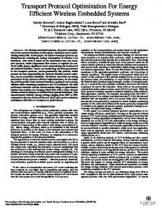
B. Level Formation In our protocol, we divide the network into 2, 3, 4 and 5 levels. The detailed description of level formation is given below. 1) Level 2: The whole network field divided into 2 levels. These levels are homogenous in terms of initial energy of nodes. Usually BS is placed in the center of the network. The formation of levels requires the distance to BS of each node. The node which is at the maximum distance from the BS has the distance Dmax. Levels are defined on the basis of the Dmax. The nodes which have greater distance than the (Dmax/2) are in level 2 and the other nodes are in level 1 Since it is a 100m × 100m network so the maximum distance from the BS to the nodes can be 70m. So the nodes which have less than 35 m distance from the BS are in level 1 and the other nodes are in level 2. 2) Level 3: In three level network, the whole network is divided into 3 levels on the basis of the maximum distance, Dmax . The nodes whose distance from the BS is less than Dmax/3 are in level 1, and the node whose distance from the BS is greater than the Dmax/3 are in level 3 and the other nodes whose distance from the BS lies in between Dmax/3 to 2 ∗ Dmax/3 are in level 2. In fig 1, the deployment of nodes in level 3 is shown. 3) Level 4: In four level network, the whole network is divided into 4 levels on the basis of the maximum distance, Dmax . The nodes whose distance from the BS is less than 25 % of the Dmax are in level 1, and the node whose distance from the BS is greater than the 25 % of the Dmax and less than 50 % of the Dmax are in level 2. The nodes whose distance from the BS is greater than the 50 % of the Dmax and less than the 75 % of the 2 ∗ Dmax/3 are in level 3. The nodes whose distance greater than the 75 percent of the Dmax are in level 4. In fig 1, the * sign indicates level 1 nodes, the circle sign shows level 2 nodes, square sign shows level 3 nodes, diamond sign shows the level 4 nodes, + sign represents the RN and x sign show the BS. 4) Level 5: In 5 level network, the whole network is divided into 5 levels on the basis of the max distance Dmax. The nodes whose distance from the BS is less than 20 % of the Dmax are in level 1, and the node whose distance from the BS is greater than the 20 % of the Dmax and less than 40 % of the Dmax are in level 2. The nodes whose distance from the BS are greater than the 40 % of the Dmax and less than the 60 % of the 2 ∗ Dmax/3 are in level 3. The nodes who have greater than the 60 % of the Dmax and less than the 80
% of the Dmax are in level 4 and the nodes who have greater than the 80 % of the Dmax are in level 5. C. Relay Nodes 1) Relay Nodes of level 2: If the network is divided into 2 level, only 4 RNs are placed at the boundary of level 1 as shown in fig 1. + sign indicates the RN. The RNs have the same structure as normal nodes however, they are used for a specific purpose. The four RNs are equipped with same battery power. These RN do not take part in CH selection. They only receive the data form CHs of the level 2, aggregate the data and send then to the BS. The level 1 CHs and nodes can directly send their data to BS. Before forwarding the data to, level 2 CHs calculate the distance to the routing nodes and forward to the nearest routing node. 2) Relay Nodes of level 3: If the network is divided into 3 levels then four RNs are placed at the boundary of the level 1 and 4 RNs are placed at the boundary of level 2 as shown in fig 1. These RNs can not become CH. They only receive the data form level 2 and level 3 CHs and after aggregation, send data to the BS. The level 1 CHs and nodes can directly send their data to BS. CHs of the level 2 and level 3 send their data to the nearest RN, therefore the distance is minimized and nodes consume less energy in data transmission. 3) Relay Nodes of level 4: If the network is divided into 4 levels then the four RNs are placed at each boundary as shown in fig 1. They only receive the data form the level 2, level 3 and level 4 CHs and after aggregation, send data to the BS. The level 1 CHs and nodes can directly send their data to BS. CHs of the levels 2, 3 and 4 send their data to the nearest RN, therefore the distance is minimized and nodes consumes less energy. 4) Relay Nodes of level 5: If the network is divided into 5 levels then the four RNs are placed at the each boundary. They only receive the data form the level 2, level 3,level 4 and level 5 CHs and after aggregation, send data to the BS. The level 1 CHs and nodes can directly send their data to BS. CHs of the levels 2, 3, 4 and 5 send their data to the nearest RN , therefore the distance is minimized and nodes need less energy to send data. 100 90 80 70 60 50 40 30 20 10 0
0
20
40
60
80
Fig. 1: Relay nodes deployment
100
D. Setup Phase
1)
Setup phase is same as given in [7]. After the level formation of the nodes, clusters are formed. Every node selects whether it is a CH for the current round or not. Each node selects the random number from [0, 1] and compares its value with the threshold given below. If the number is greater than threshold, it will not be selected as a CH. However, if the number is less than the threshold, the node will become CH. Threshold is given below:
2) 3)
T (n) =
p , 1−(p∗(rmod(1/p))
0
if n ∈ G otherwise
5)
where p is the desired probability of CH, r is the current round, and G is the set of nodes that have not been CH in the last 1/P rounds. Using this threshold, each node will become CH at some point within 1/P rounds. E. Steady Phase In the steady phase, level 1 nodes send their data to the CHs of level 1 or directly to the BS depending on the distance. Level 2 nodes send their data to the CHs of level 2. Level 2 CHs send their data to the nearest RN nodes that are placed at the boundary of level 1. These RNs directly send their data to the BS. Level 3 CHs send their data to the nearest RNs which are places at the boundary of level 2. Level 4 CHs send their data to the nearest RNs which are places at the boundary of level 3. Level 5 CHs send their data to the nearest RNs which are places at the boundary of level 4. The RNs send data directly to the BS or send data to the next RN. Decision will be made on the basis of distance. IV.
4)
S IMULATION R ESULTS
A. Comparison of LEACH and Proposed Scheme In this section, we evaluate the performance of our proposed technique using MATLAB tool. We consider WSN with 100 numbers of nodes and with 100m× 100m field. We assume that BS is placed at the center of the area of the network. The nodes are deployed randomly in the field. As the BS is in the center so the maximum distance of any node from the BS can be 70m. We divided the whole network into 2 and 3 levels on the basis of the distance. The simulation parameters are shown in table II.
6)
1) Network Lifetime: We compare our level 2 and level 3 protocols with LEACH. Stability period of the 2 level and 3 level is much higher than the LEACH. A node is dead if its energy is less than 99.99 % of its initial energy. It can be seen from the fig 2 that first node dies at 400 rounds for LEACH, 1950 rounds for 2 level and 2050 rounds for 3 level. LEACH is a routing protocol for homogenous WSNs. Therefore, each node has 0.5J initial energy. Fig 3, shows total number of nodes which are alive. Regarding stability period and network lifetime, 3 level and 2 level scheme represent better performance than LEACH. In 2 level, level 2 CHs send their data to relay nodes. Therefore, the transmission range is minimized and nodes consume less energy. Nodes remain alive for longer rounds as shown in fig 3. In 3 level, the whole network area is divided into 3 levels. CHs of level 3 need less energy to send data to the RNs due to less distance. The stability period of the 2 level and 3 level scheme is much better than LEACH. 100
3 Level 2 Level Leach
90 80 70
Dead nodes
(
Network lifetime: Time duration from the establishment of the network till death of all nodes. a) Stability period: Time duration of network operation until its first node is dead. b) Un-stability period: Time duration from the death of first node till the death of last node in the network. Number of packets sent to BS: Number of packets sent directly to BS. Number of CH per round: Total number of CH at each round. Number of packets dropped: Packets dropped due to bad status of link. Throughput: Number of packets successfully received at the BS. Transmission delay: Duration of the packet sent from the source and received at BS.
60 50 40 30
Parameters Network Size Eo EDA Efs p k Emp Eelec
Values 100m × 100m 0.5 J 5 nJ/bit/message 10 pJ/ bit/m2 0.1 4000 bits 100 pJ/bit/m2 50 nJ/bit/m
TABLE II: Simulation Parameters
In subject to system performance, the following metrics are used for evaluation purpose.
20 10 0
0
500
1000
1500
2000
2500
3000
Number of rounds
Fig. 2: Dead nodes
2) Number of Packets Sent to BS: In fig 4, total number of packets that are sent to the BS are given. As nodes are alive for large number of rounds so more packets are sent to the BS. CH and RN both aggregate the data so less packets are sent to the BS in 2 level and 3 level schemes as compared to
−3
100
4
3 Level 2 Level Leach
90 80
x 10
3 Level 2 Level Leach
3.5 3
delay time (sec)
ALive nodes
70 60 50 40 30
2.5 2 1.5 1
20 0.5
10 0
0
500
1000
1500
2000
2500
0
3000
0
500
Number of rounds
1000
1500
2000
2500
3000
Number of rounds
Fig. 3: Alive nodes
Fig. 5: Transmission delay
LEACH. In LEACH, every CH has to send its packet to the BS. However, in 2 level and 3 level, only RN and CH of first level send their packets directly to the BS. CHs of 2nd and 3rd levels send their packet to the RNs. These RNs aggregate the data and send to the BS. In 2 level and 3 level, nodes send data to the RN. RN nodes after receiving the data from multiple CHs aggregate it and send it to BS. In this way, almost 50 % of packets sent to BS are controlled by the RN. Total number of packets sent to the BS in 2 level and 3 level scheme is more than the LEACH. Because nodes die quickly in LEACH so overall number of packets is less than proposed schemes.
4) Number of Packets Dropped and Throughput: Fig 6 shows the total number of packets received at the BS. When packets are transmitted from source to destination through wireless channel, some packets do not reach at destination due to some noise. This is called packet loss or packet drop. We use Random Uniformed Model to find the packets dropped and packets received. Packets drop is related to status of that link through which it is propagating. If a given link is in bad status, packet is dropped, otherwise it is successfully received. According to the Random Uniformed Model probability of the packet drop or the bad link is 0.3 and packet received is 0.7. In 2 level and 3 level, the total number of packets sent to the BS is less than the LEACH. The graph shows the total number of packets received in these 3 protocols. Fig 7 shows the total number of packets dropped for these three protocol. It is clear from the figure that the 2 level and 3 level scheme have less number of packets dropped than the LEACH.
4
2.5
x 10
3 Level 2 Level Leach
1.5
15000
3 Level 2 Level Leach
1
0.5
0
0
500
1000
1500
2000
2500
3000
Number of rounds
Packet Recieved
Packets to BS
2
10000
5000
Fig. 4: Packets to BS 0
3) Transmission Delay: In fig 5, transmission delay time is given for LEACH and proposed schemes. 3 level scheme has minimum delay. The packets are sent to the BS from the RN and the first level CH. As the distance between the source node and the BS is minimum, packet takes less time for reaching the destination. So the overall delay of packets for each round is less in 3 level. In 2 level scheme, delay is also less than the LEACH. LEACH has maximum delay because all the CHs send data directly to the BS. Therefore, total time of the packet to reach at the BS is increased.
0
500
1000
1500
2000
2500
3000
Number of rounds
Fig. 6: Packet received 5) Comparison: In this section, we provide the results of 2 level and 3 level scheme in terms of percentage. In fig 8, life time of the network is given in terms of the percentage. As shown in the figure, number of alive nodes of the LEACH are 45 % less than the proposed schemes. In fig 10, delay
7000
3 Level 2 Level Leach
6000
Packet Drop
5000
4000
3000
2000
1000
0
0
500
1000
1500
2000
2500
3000
Number of rounds
Fig. 7: Packet drop
Fig. 9: Packet to BS percentage
of the packets from node to the BS is given. 2 and 3 level schemes outperform the LEACH in delay as well. The 2 level scheme has 70 % and 3 level has almost 90 % less delay than the LEACH. Packet to BS are given in terms of percentage as shown in fig 9, LEACH has 15 % less packets transmitted to the BS than 2 level scheme because nodes in LEACH die quickly. However, the 3 level scheme has minimum packets sent to the BS even its nodes die much after the LEACH.
Fig. 10: Delay percentage
Fig. 8: Alive nodes percentage
B. Comparison of 4 level and 5 level Schemes In this section, we evaluate the performance of the 4 level and 5 level protocols. We consider a WSN with 100 nodes deployed in 100m × 100m field. We assume that BS is located at the center of the network. The nodes are randomly (uniformly) distributed in the field. We divided the whole network into 4 and 5 levels on the basis of the distance. We discuss different performance metrics in the following subsections in detail. 1) Network Lifetime: We compare our 4 level and 5 level protocols. It is observed that first node dies in 4 level scheme at 2030 rounds and in 5 level scheme it dies at about 2070 rounds. Stability period of the 4 and 5 level schemes have
difference of only 10-15 rounds. Fig 11 shows the number of alive nodes. The nodes in 4 level scheme send their data to the CHs, RNs and to the BS. CH has less distance from the RN than the BS. So they need less energy to send the data. Nodes consume more energy during data transmission. There is slightly difference between the 5 level scheme nodes dead than the 4 level scheme. Because distance from the CH and the RNs are less in 5 level scheme. Nodes in 5 level scheme remain alive for longer time than level 4 scheme. The dead and the alive nodes are given in fig 11 and 12 for both 4 and 5 level schemes respectively. 2) Number of Packets Sent to BS: In fig 13, packets sent to the BS are given. CHs and RNs both aggregate the data so minimum packets are sent to the BS in 4 and 5 Level schemes. When the nodes are alive for the both 4 and 5 level protocol, the packet sent to the BS are approximately same until the life time of the network is changed. In 4 level and 5 level schemes, only RNs and CHs of first level send their packets to the BS. CHs of 2nd, 3rd, 4th and 5th levels send their packets to the RNs. And these RNs aggregate the data and send to the BS. RNs after receiving the data from multiple CHs, aggregate it and send it to BS. In this way, almost 50 % of packets sent to
100 4 LeveL 5 Level
90 80
Dead nodes
70 60 50 40 30 20 10 0 2000
2100
2200
2300
2400
2500
Number of rounds
are transmitted from source to destination through wireless channel, some of them do not reach at destination due to some noise. This is called packet loss or packet drop. We use Random Uniformed Model to find the packet dropped and packets received. Packets drop is related to status of that link through which it is propagating. If a given link is in bad status, packet is dropped, otherwise it is successfully received. According to the Random Uniformed Model probability of the packet drop or the bad link is 0.3 and packet received is 0.7. The graph shows the total number of packets received in these 2 protocols. Fig 15 show the total number of packets dropped for these two protocols. It is clear from the figure that the low number of packets are dropped during transmission. Because the maximum number of packets is transmitted through RNs to the BS, so packets loss is minimized.
Fig. 11: Dead nodes 10000
4 LeveL 5 Level
9000 8000 4 LeveL 5 Level
90 80
ALive nodes
70 60 50
Packet Recieved
100
7000 6000 5000 4000 3000
40
2000
30
1000
20
0
0
500
1000
0
1500
2000
2500
3000
3500
3000
3500
Number of rounds
10 0
500
1000
1500
2000
2500
3000
3500
Fig. 14: Packet Received
4000
Number of rounds
Fig. 12: Alive nodes 4000
4 LeveL 5 Level
3500
BS are controlled by the RNs.
3000 4
Packet Drop
x 10
1.15 4 LeveL 5 Level
Packets to BS
1.1
2500 2000 1500 1000
1.05
500
1
0 0.95
0
500
1000
1500
2000
2500
Number of rounds 0.9
Fig. 15: Packet Drop
0.85 2300
2400
2500
2600
2700
2800
2900
3000
3100
Number of rounds
Fig. 13: Packet to BS
3) Number of Packets Dropped and Throughput: Fig 14 shows total number of received packets at BS. When packets
C. Comparison of Our Proposed Protocols with SEP and DEEC In this section, we provide the comparison of our proposed protocols with LEACH, SEP and DEEC protocols. Fig 16 shows the number of dead nodes. It is clear from the graph that
R EFERENCES
100
3 Level 2 Level Leach 4 Level 5 Level SEP DEEC
90 80
Dead nodes
70 60 50 40 30 20 10 0
0
500
1000
1500
2000
2500
3000
Number of rounds
Fig. 16: Dead nodes
100
3 Level 2 Level Leach 4 Level 5 Level SEP DEEC
90 80
ALive nodes
70 60 50 40 30 20 10 0
0
500
1000
1500
2000
2500
3000
Number of rounds
Fig. 17: Alive nodes
our protocol outperforms LEACH, SEP and DEEC protocols in terms of network lifetime. In SEP, LEACH and DEEC first node dies before 1500 rounds. However, in our protocols, first node dies after 1950 rounds. In fig 17, the alive nodes are given.
V.
C ONCLUSION
Many protocols have been proposed for energy efficiency like LEACH, SEP, DEEC etc. However, these protocols are not as energy efficient as required. In WSN all the sensor nodes operate on the battery power. These nodes send their data to the CH even its distance is less from the BS. The CH sends its data to the sink even if it is located far away from the BS. So CH needs more energy to transmit over the long distance which decreases life time and stability period of the network. So we introduce multilevel routing protocol which extends the network life time 4 times than the LEACH. We show that our protocol has higher throughput and less delay than LEACH. Our protocol performs better than LEACH in terms of energy consumption, network life time, throughput and delay.
[1] C.-Y. Chang and H.-R. Chang, “Energy-aware node placement, topology control and mac scheduling for wireless sensor networks,” Computer networks, vol. 52, no. 11, pp. 2189–2204, 2008. [2] S. Zeadally, S. U. Khan, and N. Chilamkurti, “Energy-efficient networking: past, present, and future,” The Journal of Supercomputing, vol. 62, no. 3, pp. 1093–1118, 2012. [3] N. A. Pantazis, S. A. Nikolidakis, and D. D. Vergados, “Energyefficient routing protocols in wireless sensor networks: A survey,” Communications Surveys & Tutorials, IEEE, vol. 15, no. 2, pp. 551– 591, 2013. [4] C. Ma, N. Liu, and Y. Ruan, “A dynamic and energy-efficient clustering algorithm in large-scale mobile sensor networks,” International Journal of Distributed Sensor Networks, vol. 2013, 2013. [5] Q. Liao and H. Zhu, “An energy balanced clustering algorithm based on leach protocol,” Applied Mechanics and Materials, vol. 341, pp. 1138– 1143, 2013. [6] A. Ahmad, N. Javaid, Z. Khan, U. Qasim, and T. Alghamdi, “(ach) 2: Routing scheme to maximize lifetime and throughput of wireless sensor networks,” Sensors Journal, IEEE, pp. 1–1, 2014. [7] W. R. Heinzelman, A. Chandrakasan, and H. Balakrishnan, “Energyefficient communication protocol for wireless microsensor networks,” in System Sciences, 2000. Proceedings of the 33rd Annual Hawaii International Conference on, pp. 10–pp, IEEE, 2000. [8] L. Qing, Q. Zhu, and M. Wang, “Design of a distributed energy-efficient clustering algorithm for heterogeneous wireless sensor networks,” Computer communications, vol. 29, no. 12, pp. 2230–2237, 2006. [9] I. F. Akyildiz, W. Su, Y. Sankarasubramaniam, and E. Cayirci, “A survey on sensor networks,” Communications magazine, IEEE, vol. 40, no. 8, pp. 102–114, 2002. [10] G. Smaragdakis, I. Matta, and A. Bestavros, “Sep: A stable election protocol for clustered heterogeneous wireless sensor networks,” tech. rep., Boston University Computer Science Department, 2004. [11] V. Mhatre, C. Rosenberg, D. Kofman, R. Mazumdar, and N. Shroff, “Design of surveillance sensor grids with a lifetime constraint,” in Wireless Sensor Networks, pp. 263–275, Springer, 2004. [12] S.-S. Wang and Z.-P. Chen, “Lcm: a link-aware clustering mechanism for energy-efficient routing in wireless sensor networks,” Sensors Journal, IEEE, vol. 13, no. 2, pp. 728–736, 2013. [13] A. J. Joseph and U. Hari, “Hexagonally sectored routing protocol for wireless sensor networks,” in International Journal of Engineering Research and Technology, vol. 2, ESRSA Publications, 2013. [14] J. Peng, T. Liu, H. Li, and B. Guo, “Energy-efficient prediction clustering algorithm for multilevel heterogeneous wireless sensor networks,” International Journal of Distributed Sensor Networks, vol. 2013, 2013. [15] V. Nazari Talooki, J. Rodriguez, and H. Marques, “Energy efficient and load balanced routing for wireless multihop network applications,” International Journal of Distributed Sensor Networks, vol. 2014, 2014. [16] M. Tahir, N. Javaid, A. Iqbal, Z. A. Khan, and N. Alrajeh, “On adaptive energy-efficient transmission in wsns,” International Journal of Distributed Sensor Networks, vol. 2013, 2013. [17] Z. Liu, Q. Zheng, L. Xue, and X. Guan, “A distributed energy-efficient clustering algorithm with improved coverage in wireless sensor networks,” Future Generation Computer Systems, vol. 28, no. 5, pp. 780– 790, 2012.