Multimodal Visualization of DTI and fMRI Data using Illustrative Methods Silvia Born1 , Werner Jainek1 , Mario Hlawitschka2 , Gerik Scheuermann3 , Christos Trantakis4 , J¨ urgen Meixensberger4 , Dirk Bartz1 1
2
ICCAS / VCM, Universit¨ at Leipzig Institute for Data Analysis and Visualization, University of California, Davis, USA 3 Institut f¨ ur Informatik, Universit¨ at Leipzig 4 Klinik f¨ ur Neurochirurgie, Universit¨ atsklinikum Leipzig
[email protected]
Abstract. Designing multimodal visualizations combining anatomical and functional brain data is a demanding task. Jainek et al. [1] applied illustrative rendering techniques to obtain a high-quality representation of the location and characteristic of brain activation areas (derived from MRI and fMRI). Here, we present the integration of DTI data into this system. Reconstructed nerve fibers connecting functional areas with each other and lower brain areas are embedded into the complex rendering pipeline. Further, we enhanced perception of depth and shape by applying silhouettes and dithered halftoning.
1
Introduction
Exploring the brain’s anatomy and function with advanced imaging modalities is common practice in medicine and the neurosciences. Multimodal visualizations of these imaging data constitute supportive tools for clinicians and researchers, because they contain all relevant information, are easy to grasp and provide new insight into the known data (concerning, e.g., spatial relationships). However, deriving these visualizations of high quality is a challenging task and an issue of ongoing research. Numerous such multimodal brain visualizations exist (such as [2, 3]) , but (to our knowledge) no illustrative approaches have been employed so far. However, they appear to be quite suitable for this task, since the goal of these methods is to mimic hand-drawn sketches (as, e.g., in anatomy atlases) and discern important from unimportant information by emphasizing major features and neglecting irrelevant details. In this paper, we, therefore, present our illustrative approach of multimodal brain visualization. Our goal is to represent the location of brain functionalities (MRI and fMRI data) and the course of connecting fiber tracts (reconstructed from DTI data), while avoiding visual clutter. Further, we aim at conveying information about the connectivity of different brain areas. The latter is especially important for understanding brain anatomy and function but also for the planning of surgical interventions in the clinical context since an injury of these structures can lead to severe neurological deficits beyond the injury of the functional areas itself.
Visualization using illustrative methods
2
7
Material and methods
The work presented here is based on a system adopting advanced illustrative rendering techniques to obtain high-quality visualizations of anatomical and functional brain data [1]. Interactive frame rates, which are achieved by an efficient GPU implementation, facilitate user interaction and the usage of additional exploration tools such as clipping, distance measurements, and annotations. The presented data is based on a clinical dataset consisting of a T1 -weighted MRI scan, an fMRI sequence (finger tapping), and a DTI dataset (baseline and six gradients). For preprocessing the brain surface, different cortical areas and the border between white and gray matter were segmented in the MRI dataset using Freesurfer [4, 5]. The fMRI dataset was analyzed and the activity map was created. 2.1
Improvement of shape perception
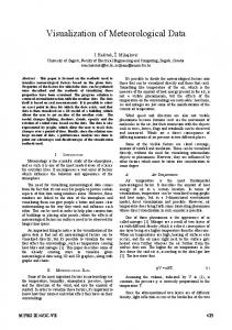
We use illustrative mesh rendering to display brain anatomy. For visualizing brain activity areas, however, direct volume rendering is applied because surface meshes depict only one activation threshold and prevent further insight into the characteristic of the activation itself. A clipping plane divides the brain into an opaque and a transparent part to improve the visibility of the activation areas (see Figure 1). Nevertheless, the exact location of these areas with respect to the cortical surface is still difficult to perceive. For the human visual system,
Fig. 1. Combined visualization of cortical anatomy, brain activity (light spot), and nervous pathways.
8
Born et al.
occlusion and motion parallax are essential cues for depth perception [6]. We enhance these depth cues by emphasizing the shape of the cortical gyri and sulci using silhouettes (detected by depth gradients and normal similarities [7]) and gentle surface shading. For surface shading, a diffuse light source and ambient occlusion shading is used. Langer and B¨ ulthoff revealed that this kind of lighting condition is most appropriate for representing shape from shading and more suitable than, e.g., using a direct light source [8]. Because the cortex surface is rendered transparently, common diffuse shading is hardly visible, and we apply dithered halftoning according to [7]. This illustrative method is capable of conveying diffuse lighting and ambient occlusion shading [9] on transparent surfaces without introducing clutter. 2.2
Integration of nerve fibers
The exploration of diffusion tensor data allows insight into the path of nerve fibers and thus the connectivity of brain areas. Diffusion information can be visualized either directly, e.g., by glyphs [10] or by reconstructed fiber tracts using streamlines or streamtubes [11]. We use streamtubes because they are easier to interprete and provide better depth perception. For the streamtubes, a second-order tensor field was reconstructed from the six diffusion-weighted DTI scans by a linear least-squares fit [12] using the Stejskal-Tanner formula [13]. Then, fourth-order Runge-Kutta integration is applied to construct the fiber tracts by trilinear interpolation on the tensor field [14]. A lower limit on the fractional anisotropy is used to ensure that fibers are only propagated in areas with anisotropic diffusion characteristic. The obtained geometrical models are integrated into the scene, which is divided into several layers depending on position of camera, clipping plane, and surface meshes. All layers are rendered into textures for intermediate storage, which are then combined for the final render output. During these steps, the rendering of illustrative elements, such as silhouette detection and shading, is carried out. For further details about the general rendering pipeline, please refer to [1].
3
Results
The final visualization (see Figure 1) gives the user detailed insight into the structure of the brain (e.g., shape of gyri and sulci, position of different cortical areas, the border between white and gray matter, and cortical thickness) and location and characteristic of the fMRI activation areas. Nervous pathways connecting functional areas of interest or leading from functional to lower brain areas, can also be detected rather easily in this visualization. However, fiber tracking is only possible in the white matter, whereas the activation areas are located in the gray matter. Therefore, the visualized connection between nerve fibers and functional areas is no precise but an approximated contact or infiltration.
Visualization using illustrative methods
9
Fig. 2. Enhancement of shape and depth perception with silhouettes (b) and additional dithered halftoning (c). Applying only slight surface shading on a transparent surface provides hardly any depth cues (a).
(a)
(b)
(c)
The enhancements concerning shape and depth perception are displayed in Figure 2. The activation areas are partly occluded by the silhouettes and shaded areas (dithered halftoning) depicting the brain surface. Due to these two effects and motion parallax, which arises during user interaction, the ability to locate these brain functions is improved considerably. The preprocessing time is rather high, since the segmentation of the MRI data requires several hours of runtime. The fMRI analysis is carried out in the department for neuroradiology. Concerning the DTI data, the creation of the tensor field takes less than one second and the fiber tracking can be computed in about 10 seconds. Per frame a total of about 3.7 million triangles and 180 volume slices are rendered. On a Windows machine (Intel Core 2 Duo Processor T8300 (2.4GHz), 4GB RAM, Nvidia GeForce 8600M GS graphics card) a frame rate of 2.8 is achieved for the visualization as illustrated in Figure 1 (output resolution of 700x700 pixels).
4
Discussion
We have presented an illustrative approach for a combined display of MRI, fMRI, and DTI data. Several methods have been used to include a great amount of information into the visualization, while keeping it uncluttered and easy to understand. Effort has been put into obtaining a good shape perception of the cortical surface and the visualization of the location of brain function. Therefore, the shape of the transparently rendered brain surface has been accentuated by stronger silhouettes and shading effects (dithered halftoning). Furthermore, streamtubes representing nerve fibers have been reconstructed from DTI data and integrated into the visualization system.
10
Born et al.
Suitable applications are high-quality visualizations of research results in the area of the neurosciences where brain anatomy, function, and especially connectivity play an important role. The integration of further DTI visualization techniques (e.g., illuminated streamlines) conveying brain connectivity are planned. Moreover, this visualization approach can be applied as a digital and interactive brain atlas helping medical students explore and understand brain anatomy and the connectivity of different areas. In addition to the already implemented annotations of the different cortex areas, adding further structures such as blood vessels, ventricles, or pathologies (tumors) would provide more orientation and insight into the brain anatomy and interconnectivity. In any case, a trade-off between a higher number of structures and visual clutter needs to be found, e.g., by focus-and-context renderings according to specific user queries.
References 1. Jainek W, Born S, Bartz D, et al. Illustrative hybrid visualization and exploration of anatomical and functional brain data. Computer Graphics Forum. 2008;27(3):855–862. 2. K¨ ohn A, Weiler F, Klein J, et al. State-of-the-art computer graphics in neurosurgical planning and risk assessment. Proc Eurographics Short Papers. 2007; p. 117–120. 3. Beyer J, Hadwiger M, Wolfsberger S, et al. High-quality multimodal volume rendering for preoperative planning of neurosurgical interventions. Proc IEEE Visualization. 2007; p. 1696–1703. 4. Fischl B, Liu A, Dale A. Automated manifold surgery: Constructing geometrically accurate and topologically correct models of the human cerebral cortex. IEEE Trans Med Imaging. 2001;20(1):70–80. 5. Fischl B, van der Kouwe A, Destrieux C, et al. Automatically parcellating the human cerebral cortex. Cerebral Cortex. 2004;14:11–22. 6. Goldstein E. Sensation and perception. Belmont: Wadsworth Publishing; 2006. 7. Strothotte T, Schlechtweg S. Non-photorealistic computer graphics. San Francisco: Morgan Kaufman; 2002. 8. Langer M, B¨ ulthoff H. Perception of shape from shading on a cloudy day: Technical report No.73. T¨ ubingen: Max-Planck-Institut f¨ ur Biologische Kybernetik; 1991. 9. Jainek W. Illustrative Visualization of Brain Structure and Functional MRI Data. T¨ ubingen: Eberhard-Karls-Universit¨ at; 2007. 10. Kindlmann G, Westin C. Diffusion tensor visualization with glyph packing. Proc IEEE Visualization. 2006; p. 1329–1335. 11. Zhang S, Demiralp C, Laidlaw D. Visualizing diffusion tensor MR images using streamtubes and streamsurfaces. IEEE Trans Vis Comput Graph. 2003;9(4):454– 462. 12. Basser P, LeBihan D. Fiber orientation mapping in an anisotropic medium with NMR diffusion spectroscopy. Proc Ann Meet Soc Magn Reson Med. 1992; p. 1221. 13. Stejskal E, Tanner J. Spin diffusion measurements: Spin echoes in the presence of a time-dependent field gradient. J Chem Phys. 1965;42:288–292. 14. Weickert J, Hagen H. Visualization and Processing of Tensor Fields. Berlin: Springer; 2005.