Multiobjective Design Optimization of Merging Configuration for an Exhaust Manifold of a Car Engine Masahiro Kanazaki*, Masashi Morikawa**, Shigeru Obayashi* and Kazuhiro Nakahashi** *Institute of Fluid Science, Tohoku University, Sendai 980-8577, Japan E-mail:
[email protected] URL: http://www.reynolds.ifs.tohoku.ac.jp/edge/ **Dept. of Aeronautics and Space Engineering, Tohoku University, Sendai 980-8579, Japan
Abstract. Multiobjective design optimization system of exhaust manifold shapes for a car engine has been developed using Divided Range Multiobjective Genetic Algorithm (DRMOGA) to obtain more engine power as well as to achieve less environmental impact. The three-dimensional manifold shapes are evaluated by the unstructured, unsteady Euler code coupled with the empirical engine cycle simulation code. This automated design system using DRMOGA was confirmed to find Pareto solutions for the highly nonlinear problems.
1. Introduction To improve intake/exhaust system performance of a car engine, many design specifications are required. In addition, car engines today are required not only to have more engine power, but also to be more environmentally friendly. Exhaust gas should be kept at high temperature in the exhaust pipe especially at low rpm conditions because the catalyst located at the end of the exhaust pipe will absorb more pollutant in high temperature conditions. Exhaust gas should also be led from the piston chambers to the exhaust manifold smoothly to maximize the engine power especially at high rpm conditions. Such design usually has to be performed by trial and error through many experiments and analyses. Therefore, an automated design optimization is desired to reduce technical, schedule, and cost risks for new engine developments. In the previous study, the design system that could account for multiple design objectives has been developed and the exhaust manifold excellent at the emission control was obtained [1]. However, the engine power was not improved very well, because the baseline manifold was for the car engine of a popular car. In this paper, the high power engine of a sports car is considered for multiobjective optimization to increase the engine power as well as to reduce the environmental impact. The baseline manifold is shown in Fig. 1. To further improve the design optimization system, this paper employs Divided Range Multiobjective Genetic Algorithm (DRMOGA) [2]. DRMOGA have the advantage over the previous MOGA [1], because it can retain diversity of the population better than MOGA.
Junction #1
#1
#2
#3
#4
Junction #2
Junction #3
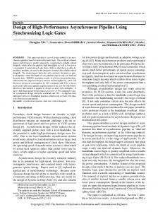
Fig. 1. The initial manifold shape and design variables as junction positions on pipe centerlines
2.
Formulation of the optimization problem
2. 1. Objective functions The objective functions considered here are to maximize the gas temperature at the end of the exhaust pipe at 1,500 rpm and to maximize the charging efficiency at 6,000 rpm, where the charging efficiency indicates the engine power. These two objectives are function of a flow over an engine cycle. A flow field of a manifold shape is computed by solving a unsteady three-dimensional inviscid flow code [3]. Unsteady boundary conditions for a flow to and from a manifold are simultaneously computed by using the one-dimensional, empirical engine cycle simulation code [1, 4]. 2. 2. Divided Range Multiobjective Genetic Algorithm In this study, the automated design optimization system is developed by using DRMOGA [2]. DRMOGA is characterized by the operation where the individuals are
divided into subpopulations. DRMOGA procedure (Fig. 2) can be explained as follows. First, initial individuals are produced randomly and evaluated. Second, the division of individuals is performed based on the ranking of individuals sorted by values of a focused objective function fi. Assuming m subpopulations for N individuals, N/m individuals will be allocated to each subpopulation. Then in each subpopulation, the existing MOGA is performed. After MOGA is performed for k generations, all of the individuals are gathered and they are divided again according to another objective function fj. This focused function will be chosen in turn. DRMOGA is known to enhance the population diversity and to produce a better Pareto front [2]. The subdivision of the population based on alternative objective functions prevents the premature convergence to a Pareto front segment and introduces migration of individuals to neighboring Pareto front segments. In this study, MOGA utilized real-number cording [5], the Pareto ranking method [6], BLX-0.5 [5] and Best-N selection [7] and mutation rate was set to 0.1. Function evaluations in MOGA were parallelized on SGI ORIGIN2000 supercomputer system at the Institute of Fluid Science, Tohoku University. For DRMOGA, k was set to 8 and number of subpopulation was set to 2. 2. 3. Geometry definition To generate a computational grid according to given design variables, an automated procedure to find a pipe junction from pipe centerlines was developed in the previous study [1] as shown in Fig. 3. In this method, temporary background grids are first generated from the given centerlines. Then the overlap region of the pipes is calculated and removed. The advancing-front method [8] is then applied to generate the computational surface grid by specifying the junction as a front. With this method, various merging configurations can be generated only by specifying the merging points on the pipe centerline. In this study, the initial manifold shape is taken from an existing engine with four pistons as shown in Fig. 1. Topology of the merging configuration is kept unchanged. The pipe shape traveling from the port #2 to the outlet is also fixed. Three merging points on the pipe centerlines, junctions #1-3, are considered as design variables. Pipe centerlines of #1, 3 and 4 are then deformed similarly from the initial shapes to meet the designed merging points. The pipe shapes are finally reconstructed from the given pipe radius. This method allows the automated grid generation for arbitrary merging configuration defined by the pipe centerlines. This study considered two design cases. The first case assumes a constant pipe radius for all pipes, therefore only three merging points are to be designed. In the second case, the pipe radius of the entire exhaust manifold is considered as a design variable because the pipe radius is known important for the performance of the exhaust manifold from the experiences at the industry. The pipe radius will change from 83% to 122% of the original radius. In the second case, three merging points and the pipe radius are to be designed simultaneously.
Division Initialization
Evaluation
F2
F1
Gathering
MOGA (k generations) Fig. 2. Procedure of DRMOGA
#2 overlap
#2
#1 #2
#1
#1
Fig. 3. Surface definition with arbitrary pipe junction
3.
Design optimization of an exhaust manifold
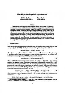
3. 1. Design problems In this study, two design problems were considered. First, the design optimization of merging points was performed (Case 1). The population size was set to 32. The evolution was advanced for 25 generations. Second, the merging points and pipe radius were optimized at the same time (Case 2). In this case, the population size was set to 64. The evolution was advanced for 29 generations. 3. 2. Comparison of solution evolutions In Case 1, Pareto solutions were found as shown in Fig. 4(a). Many solutions achieve much higher charging efficiency than the initial geometry. These results suggest that the merging points are effective design variables to improve in the charging efficiency that indicates the engine power. However, the improvement in the temperature remained marginal. In Case 2, Pareto solutions were found as shown in Fig. 4(b). Improvements in both objective functions were achieved. The Pareto front also confirms the tradeoff between the two objectives. This result suggests that the pipe radius is effective to maximize the temperature at the end of the exhaust manifold. 3. 3. Comparison of designed shapes of selected Pareto solutions Manifold geometries taken from two Pareto solutions in Case 1 are shown in Fig. 5(a). The initial shape is drawn with the mesh in a dark color. The solution A achieved the highest charging efficiency and the solution B achieved the highest temperature. The distance from the merging point #1 to #3 of the solution A became longer than that of the initial manifold. Such a merging shape is expected to reduce the interaction of the exhaust gas led from chambers and thus to lead to a high charging efficiency. On the other hand, the solution B has the tendency such that the distance from one junction to others becomes shorter. Manifold geometries taken from four Pareto solutions in Case 2 are shown in Fig. 5(b). The solution C in Case 2 shows the same tendency as the solution A in Case 1. The pipe radii of solutions C and D remained almost unchanged compared with that of the initial manifold. On the other hand, the solutions E and F achieved much higher temperature than the solutions B in Case 1. Moreover, their pipe radii became larger than that of the initial manifold. These comparisons reveal the tradeoff in maximizing the charging efficiency and the temperature of the exhaust gas.
Initial
B
87.5
Charging efficiency (%)
Charging efficiency (%)
A 90
85
C
90
D E
Initial
87.5
F 85
1490
1500 1510 Temperature (K)
1520
1490
(a)
1500 1510 Temperature (K)
1520
(b)
Fig. 4. All solutions produced by DRMOGA plotted in the objective function space; (a) Case 1, merging points optimization, (b) Case 2, merging points and pipe radius optimization
Junction #3
Junction #3 Junction #1
A (Maximum charging)
Junction #1
B (Maximum temperature)
(a)
C (Maximum charging)
F (Maximum temperature)
E
D
(b) Fig. 5. Manifold shapes of selected from Pareto solutions; (a) Case 1, merging points optimization, (b) Case 2, merging points and pipe radius optimization
4. Concluding remarks An improved design optimization system of an exhaust manifold of a car engine has been developed. The design system employs DRMOGA. The three-dimensional manifold shapes are evaluated by the unstructured, unsteady Euler code coupled with the empirical engine cycle simulation code. Computational grids were automatically generated from the designed merging points on pipe centerlines. The initial configuration of the manifold was taken from an existing high power engine with four cylinders. At first, the manifold shape was optimized by three merging points on the pipe centerlines, assuming the pipe radius constant. The present system found optimal solutions mainly improved in the charging efficiency. This result suggests that the merging configuration is very effective to improve the charging efficiency. The second case optimized both the pipe radius and merging points. Not only the charging efficiency but also the exhaust gas temperature was improved in this case. This result suggests that the pipe radius is important to improve the exhaust gas temperature. The present system has successfully found solutions that have less environmental impact and more engine power simultaneously than the initial design. The resulting Pareto front also reveals the tradeoff between the two objectives.
5. Acknowledgements We would like to thank Powertrain Research Laboratory in Mazda Motor Corporation for providing the one-dimensional empirical engine cycle simulation code and the engine data. The calculations were performed by using the supercomputer, ORIGIN 2000 in the Institute of Fluid Science, Tohoku University.
6.
References
[1] M. Kanazaki, S. Obayashi and K. Nakahashi, “The Design Optimization of Intake/Exhaust Performance of a Car Engine Using MOGA,” EUROGEN 2001, Athens, Sep. 19-21, 2001, postproceedings in print. [2] T. Hiroyasu, M. Miki and S. Watanabe, “The New Model of Parallel Genetic Algorithm in Multi-Objective Optimization Problems (Divided Range Multi-Objective Genetic Algorithm),” IEEE Proceedings of the Congress on Evolutionary Computation 2000, Vol. 1, pp.333-340, 2000. [3] D. Sharov, and K. Nakahashi, “Reordering of 3-D Hybrid Unstructured Grids for LowerUpper Symmetric Gauss-Seidel Computations,” AIAA J., Vol. 36, No. 3, pp. 484-486, 1998. [4] K. Ohnishi, H. Nobumoto, T. Ohsumi and M. Hitomi, “Development of Prediction Technology of Intake and Exhaust System Performance Using Computer Simulation,” MAZDA Technical Paper (in Japanese), No. 6, 1988. [5] L. J. Eshelman and J. D.Schaffer, “Real-coded genetic algorithms and interval schemata,” Foundations of Genetic Algorithms2, Morgan Kaufmann Publishers, Inc., San Mateo, pp. 187-202, 1993.
[6] C. M. Fonseca and P. J. Fleming, “Genetic algorithms for multiobjective optimization: formulation, discussion and generalization,” 5th International Conference on Genetic Algorithms, Morgan Kaufmann Publishers, San Francisco, pp. 416-423, 1993. [7] K. A. De Jong, “An Analysis of the Behavior of a Class of Genetic Adaptive System,” Doctoral Dissertation, University of Michigan, Ann Arbor, 1975. [8] Y. Ito and K. Nakahashi, “Direct Surface Triangulation Using Stereolithography (STL) Data,” AIAA Paper 2000-0924, 2000.