Mar 12, 2012 - Linac driven free electron lasers (FELs) operating in the x-ray region require a high ... The application to the proposed UK's New Light Source.
PHYSICAL REVIEW SPECIAL TOPICS - ACCELERATORS AND BEAMS 15, 030701 (2012)
Multiobjective genetic algorithm optimization of the beam dynamics in linac drivers for free electron lasers R. Bartolini,1,2 M. Apollonio,1 and I. P. S. Martin1 1
Diamond Light Source, Oxfordshire, OX11 0DE, United Kingdom John Adams Institute, University of Oxford, OX1 3RH, United Kingdom (Received 16 December 2011; published 12 March 2012)
2
Linac driven free electron lasers (FELs) operating in the x-ray region require a high brightness electron beam in order to reach saturation within a reasonable distance in the undulator train or to enable sophisticated seeding schemes using external lasers. The beam dynamics optimization is usually a time consuming process in which many parameters of the accelerator and the compression system have to be controlled simultaneously. The requirements on the electron beam quality may also vary significantly with the particular application. For example, the beam dynamics optimization strategy for self-amplified spontaneous emission operation and seeded operation are rather different: seeded operation requires a more careful control of the beam uniformity over a relatively large portion of the longitudinal current distribution of the electron bunch and is therefore more challenging from an accelerator physics point of view. Multiobjective genetic algorithms are particularly well suited when the optimization of many parameters is targeting several objectives simultaneously, often with conflicting requirements. In this paper we propose a novel optimization strategy based on a combination of multiobjective optimization with a fast computation of the FEL performance. The application to the proposed UK’s New Light Source is reported and the benefits of this method are highlighted. DOI: 10.1103/PhysRevSTAB.15.030701
PACS numbers: 41.60.Cr, 41.85.�p
I. INTRODUCTION With the successful operation of the Linac Coherent Light Source (LCLS) in the USA [1], SACLA X-FEL in Japan [2], FERMI at ELETTRA in Italy [3], and FLASH in Germany [4], free electron lasers (FELs) operating in the x-ray region have been firmly established as powerful tools for enabling new scientific research. Most of the existing projects rely on a high brightness electron gun, followed by a linear accelerator to reach the operating energy, equipped with one or more magnetic compression stages to reach the required peak current. Maintaining high brightness during the acceleration and compression process is the main goal of beam dynamics optimization in the linac. The basic selfamplified spontaneous emission (SASE) mode of operation [5] demands a large peak current, small normalized emittance, and small energy spread. Each portion of the bunch with sufficient beam quality, and with a length equal to the FEL cooperation length, will then radiate an independent SASE spike so that the time coherence of SASE pulses is limited. In general, all slices with sufficient beam quality will lase independently and with different saturation lengths. Modern trends in the development of such sources include the generation of Fourier transform limited pulses
Published by the American Physical Society under the terms of the Creative Commons Attribution 3.0 License. Further distribution of this work must maintain attribution to the author(s) and the published article’s title, journal citation, and DOI.
1098-4402=12=15(3)=030701(8)
with an external laser seed or the generation of ultrashort radiation pulses (down to sub-fs). In fact, a seeded FEL is capable of extending the temporal coherence beyond the FEL cooperation length up to the length of the seed pulse. However, the operation of a seeded FEL puts some additional constraints on the optimization of the electron beam dynamics. Schemes such as the fresh bunch technique or the high gain harmonic generation (HGHG) [6], cascaded HGHG [7], or ECHO-enabled harmonic generation (EEHG) [8] intrinsically pose a tighter requirement on the energy spread of the beam with respect to SASE operation. Furthermore, seeded schemes force the optimization to control the beam uniformity not simply over one or a few cooperation lengths but continuously over the full seed length and beyond. In fact, the presence of nonuniformities along the bunch will be amplified by the intrinsic instability of the FEL process and will unavoidably reduce the temporal coherence of the FEL pulse below that of the laser seed. Likewise, the presence of accidentally good slices may generate SASE spikes which reach saturation before the rest of the FEL pulse and spoil the contrast ratio of the pulse. The length of the portion of the electron bunch with constant slice parameters should extend beyond the seed pulse length in order to take into account the possibility of relative jitter in the arrival time of the electron bunch with respect to the laser seed pulse. Such length depends therefore not only on the required FEL coherence length, but also on the details of the linac design and rf technology which define the arrival time jitter of the bunch. In this way we make sure that, even in presence of time jitter, the seed laser pulse will always
030701-1
Published by the American Physical Society
R. BARTOLINI, M. APOLLONIO, AND I. P. S. MARTIN overlap with a portion of the electron bunch with constant slice parameters. Usually, the beam dynamics optimization is performed with extensive start-to-end simulations which take into account collective effects, such as coherent synchrotron radiation (CSR), longitudinal space charge (LSC), and longitudinal and transverse wakefields in the accelerating structures. The actual optimization of the linac design can be a long and complicated process, in which a large number of machine parameters have to be controlled and the objective functions can be mutually conflicting (e.g. small emittance and high peak current). It has been recognized that, for this kind of problem, multiobjective genetic algorithms (MOGA) [9] can provide interesting solutions and insight in the potential performance of an accelerator. They have been used to study accelerator physics problems such as the optimization of the performance of a DC photocathode gun [10], the optimization of the dynamic and momentum apertures of a storage ring [11] of a damping ring [12] and of the beam dynamics in the International Linear Collider [13]. In this paper we propose to extend their applicability to the design of a linac for driving a seeded FEL. In Sec. II we present the rationale behind the optimization strategy of a linac driven seeded FEL, the criteria for the optimization, and the algorithm used. In Sec. III we show the results of the application of MOGA to the optimization of the UK’s New Light Source (NLS) linac design [14]. We found that the minimization of the gain length and the uniformity of the gain length along the bunch slices are conflicting objectives and that MOGA allows the best trade-off between the two to be found. The algorithm also clearly allows a three bunch compressor arrangement to be discriminated from a one or two bunch compressor design for the particular case of the NLS. Conclusions will be drawn in Sec. IV. II. OBJECTIVES AND OPTIMIZATION STRATEGY The basic parameter which describes the exponential amplification regime in a high gain FEL is the Pierce parameter [5] � 2 � K ½JJ�2 k2p 1=3 �¼ ; 32 k2u where K is the undulator parameter, ½JJ� is the Bessel factor for a planar undulator given by ½JJ� ¼ ½J0 ð�Þ � J1 ð�Þ� with � ¼ K2 =ð4 þ 2K2 Þ, ku is the undulator wave number, and kp is the longitudinal plasma oscillation wave pffiffiffiffiffiffiffiffiffiffiffiffiffiffiffiffiffiffiffiffiffiffiffiffiffiffiffiffi number defined as kp ¼ 2Ie =ð�3 IA �2x Þ with Ie the peak current of the bunch, IA the Alfen current, � the electrons’ relativistic factor, and �x the rms transverse size of the beam. The Pierce parameter is related to the gain length of the FEL by � Lg ¼ puffiffiffi ; (1) 4� 3�
Phys. Rev. ST Accel. Beams 15, 030701 (2012) where �u is the undulator period. For SASE operation, the saturation is usually reached within 18 to 20 gain lengths [15]. The gain length can be substantially increased when realistic properties of the electron beam are considered. A convenient parametrization of the effect of emittance, energy spread, and diffraction on the gain length is provided by the semianalytical estimate devised by Xie [16]. SASE and seeded FELs operating in the x-ray region usually require beams with kA peak current, with a normalized emittance lower than 1 �m and energy spread in the order of 10�4 . In both cases, the optimization should deliver a beam with adequate slice quality to have the shortest possible gain length. The start-to-end simulations used to optimize the beam dynamics in the linac usually split the machine in three sections: the injector, where transverse space charge forces dominate the beam dynamics, the linac where acceleration and compression take place in the presence of CSR, LSC, and wakefields in the accelerating structure, and finally the undulator sections, where the lasing process builds up. In our simulations, we used the code ASTRA [17] in the injector, ELEGANT [18] in the linac, and GENESIS [19] for the FEL. The linac parameters used in the optimization are the amplitude and phase of the accelerating cavities and the strength of the bunch compressors while the objectives chosen are the gain length and gain flatness over a portion of the bunch 100 fs long. This value is the result of the arrival time jitter analysis for the UK’s New Light Source (NLS) [14] showing that the relative jitter of a 20 fs FWHM laser seed pulse can be accommodated within such a time span. The simultaneous optimization of these two objectives as a function of the linac operating parameters is a problem well suited to the application of the MOGA type of algorithm such as nondominated sorting genetic algorithm II (NSGA-II) [9]. NSGA-II is a computationally efficient algorithm used to find a Pareto-optimal set of solutions, none of which is strictly worse than (dominated by) the others according to the optimization criteria. The population is sorted into fitness order by the number of strictly dominating solutions, known as the Pareto rank. After sorting, the population undergoes tournament selection, polynomial mutation, and simulated binary crossover to generate new solutions by combining features of the fittest parents. The least fit children are discarded. The zeroranked Pareto set after N iterations is the result of the optimization. Our implementation of the NSGA-II algorithm is written in PYTHON [20] and uses message passing interface (MPI) [21] to distribute population members across computing nodes. The AP cluster at Diamond runs Sun Grid Engine and has 30 nodes, each with 2 quad core Xeon E5430 processors and 16 GB of RAM. Twenty-four nodes are 4xDDR Infiniband enabled to improve the performance of MPI jobs such as GENESIS. The cluster has shared access to a 200TB Lustre parallel file system. The simulations of the beam dynamics in the linac usually require a large number of macroparticles in order
030701-2
MULTIOBJECTIVE GENETIC ALGORITHM OPTIMIZATION . . . Phys. Rev. ST Accel. Beams 15, 030701 (2012) to avoid an instability effect which arises from numerical noise rather than true physical effects [22,23]. Furthermore, the FEL interaction is usually computed with time-dependent simulations in order to get a full characterization of the FEL radiation pulse. The implementation of such a scheme in a MOGA optimizer appears challenging. Indeed, both the tracking in the linac and the time-dependent FEL computation would require prohibitively large computation time even with good size clusters as the one available at Diamond. A key ingredient in the effective implementation of the multiobjective genetic algorithms is the definition of objective functions which can be computed quickly in order to explore a large subset of the phase space parameters of the problem. The computation of each vector of objectives in the above case would require a full ELEGANT simulation and a time-dependent GENESIS simulation. It is clear that one has to find an adequate trade-off between computation time and numerical accuracy. In particular, the number of particles in the ELEGANT simulations has to be limited to a few hundred thousand. We found that simulation with 100 k particles is already sufficient to identify good solutions, whose quality is preserved when extending the simulation to a significantly larger number of particles (up to 2 M). Likewise, full blown time-dependent simulations following the evolution of the FEL pulse over the whole electron bunch are in practice unusable for a fast determination of the gain length and the gain uniformity within the MOGA optimizer. A quick proxy can be given by performing the slice analysis of the beam at the undulator using the Xie parametrization of the 3D gain length of the FEL. Although this is an effective estimate for a first evaluation of the quality of the solutions, we found that the effects neglected by the semianalytical Xie parametrization can significantly impact the FEL performance. In particular, we found it necessary to go beyond the limits of the Xie length parametrization to include beam size variation along the undulator train and beam angles and offsets. As such, we opted for a computation of the FEL gain length using GENESIS in time independent mode. The computation of the gain is made by selecting a number of slices along the targeted portion of the bunch and feeding each of these to a separate GENESIS time independent run. In our case, we found that forty slices of 2.5 fs were sufficient to have a length per slice comparable to the cooperation length and to cover the total region of interest of 100 fs. The GENESIS simulations take into account the slice emittance, the peak current, the relative energy spread, the Twiss parameters, the offset, and angle of each slice. Furthermore, the magnetic structure is properly described including focusing elements and undulator interruptions. The final gain length used by the optimizer is the average hLg i of the gain lengths over a portion of the bunch sufficient to accommodate the seed pulse laser and the arrival time jitter. The gain uniformity is computed as the rms of the gain lengths
�Lg of all the slices considered. In this way the optimization penalizes variations of Lg along the bunch and also the accidentally good slices which might generate SASE spikes spoiling the contrast ratio. With such a choice of objective functions, the computation of a full front with a population of 100 individuals in the AP cluster at Diamond is completed in 23 minutes. Controlling the energy chirp at the end of the linac is an important aspect of the optimization process. In order to help the algorithm find solutions with small energy deviations in the 100 fs selected window, we opted for the following strategy: for each of the forty 2.5 fs slices of the bunch, the gain length Lg is penalized as in Lg;chirp ¼ Lg ð1 þ PÞ
(2)
if the energy of the slice is too offset. We found that an exponential penalization function P defined as � � � � �MAX P ¼ exp n ; �� where �n ¼
j�n � �0 j ; �0
is the relative energy deviation and �� is the slice relative energy spread, is adequate to discard solutions which develop a relative energy chirp larger than �MAX . In fact, the definition of the modified gain length Lg;chirp will highly disfavor the solutions with large relative energy chirp in the optimization process, even if they might potentially be acceptable in terms of slice emittance, peak current, and energy spread. The value of �MAX is usually taken to be equal to the gain bandwidth of the FEL, i.e., equal to the Pierce parameter. The resulting front will produce solutions with a good energy chirp, within the limits set by the penalty function. The electron beam quality is required to be uniform, regardless of the seeded scheme adopted (e.g. HGHG, cascaded HGHG, or EEHG). If the optimization is targeting only SASE operation, then the same algorithm can be run using simply the gain length as the only objective. We finally observe that this algorithm can be easily extended to include the rf gun optimization, by tying up the rf gun parameters such as gradient, solenoid, distance of the first accelerating structure, laser pulse length, and shape directly to the FEL parameters. In the same way, one can extend the optimization to complex transfer lines which might be required to distribute the electron bunches to different FEL lines. The extension to additional objectives such as FEL peak power and pulse energy in SASE mode is straightforward. For such an extension to the seeded operation, it is not yet evident how to include the effect of time jitter on the FEL performance without resorting to full time-dependent GENESIS simulations. This will be the object of forthcoming studies.
030701-3
R. BARTOLINI, M. APOLLONIO, AND I. P. S. MARTIN
Phys. Rev. ST Accel. Beams 15, 030701 (2012)
FIG. 1. Layout of the NLS linac with three bunch compressors and naming conventions for the parameters used in the optimization.
FIG. 2. Layout and optics functions of the NLS linac: (left) the baseline case with three bunch compressors and (right) the case study with two bunch compressors (see text for explanation).
III. RESULTS FOR THE NLS The New Light Source (NLS) was a project for an advanced fourth generation light source, which produced a conceptual design comprising a suite of three seeded FELs driven by a single 2.25 GeV superconducting linac [14]. A schematic of the NLS facility layout is shown in Fig. 1. In the baseline design used in this paper [24], 135 MeV, 0.2 nC low-emittance electron bunches are generated in an injector section consisting of an L-band normal conducting rf gun [25] and one 1.3 GHz TESLA-type superconducting rf cavity module [26]. Downstream of the injector is a laser heater (which increases the uncorrelated energy spread to combat the microbunching instability) and a third harmonic cavity (for phase space linearization). Following this, the beam is accelerated to 2.25 GeV by a further fourteen rf cavity modules, during which the bunches are gradually compressed from 15 ps FWHM to 180 fs FWHM using three magnetic chicanes. This takes the peak current from 15 A at the exit of the injector to 1.1 kA at the undulator entrance. The bunch compression ratios are 2, 4, and 10.4, and the energies at which compression occurs are 120 MeV, 450 MeV, and 1.25 GeV, respectively. Following the main linac is a collimation section (for removal of beam halo and off-energy particles) and a spreader section which distributes the beam to the three FELs. The three FEL lines are constructed from a series of APPLE-II undulator modules interleaved in a focusingdefocusing quadrupole array (FODO), with each one designed to operate within a different wavelength range.
In each case a 50–100 eV high harmonic generation laser seed is used, with the desired FEL radiation wavelength reached by up-converting the seed laser wavelength in a cascaded harmonic generation scheme. In this study we have concentrated on FEL3 operating at 1 keV in the
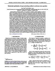
FIG. 3. Pareto-optimal fronts for the optimization of the objective with the NSGA-II MOGA. The four hues of green refer to the 5, 25, 50, and 100 iteration fronts. A comparison with the result of a random search (blue dots) is reported. The inset shows the zoom of the optimal front in the best region of the objective. The red dot shows a chosen solution whose parameters are plotted in Fig. 4 (see text for more explanations).
030701-4
MULTIOBJECTIVE GENETIC ALGORITHM OPTIMIZATION . . . Phys. Rev. ST Accel. Beams 15, 030701 (2012)
FIG. 4. Phase space and slice analysis for the electron bunch on the Pareto-optimal front selected from Fig. 3 and corresponding to the red dot. Current distribution (top left), normalized emittance distribution (middle left), gain length per slice (bottom left), longitudinal phase space (top right), ðx; tÞ phase space (middle right), and ðxp ; tÞ phase space (bottom right).
fundamental, as this mode of operation presents the most challenging requirements on the electron bunch properties. The optics functions in the linac are reported in Fig. 2. The first compressor is a C-type chicane while the
remaining two compressors are of S-type. The parameters used in the MOGA were the strength of the three bunch compressors, the voltage and phase of the two accelerating sections before the second bunch compressor, and the
030701-5
R. BARTOLINI, M. APOLLONIO, AND I. P. S. MARTIN voltage and phase of the third harmonic cavity, making a total of seven parameters. The optimization procedure always includes the correct matching of the optics functions at the end of the linac and a matching section is also present after each magnetic bunch compressor. In this way the projected beam parameters at the beginning of the undulator train are always the same. The result of the MOGA optimization is shown in Fig. 3 where we report some of the fronts at different stages of the optimization in the space of the objectives. Figure 3 also reports a comparison of the algorithm with a purely random choice of the
FIG. 5. Determination of ðLg ; �Lg Þ for the 100 iteration front solution chosen from Fig. 3 (red dot). (Top) Power as a function of the undulator length as computed by GENESIS for each bunch slice. Dark blue curves refer to slices within the 100 fs time window around the bunch centroid of charge; cyan curves refer to slices lying out of the aforementioned region. The slope of each power curve is calculated between 9.18 and 22.17 m (red band) and the average curve is plotted in orange. (Bottom) beam rms envelopes inside the undulator. Darker colors refer to slices within the 100 fs selection. Lighter hues show beam envelopes for cases outside the selected region.
Phys. Rev. ST Accel. Beams 15, 030701 (2012) parameters where the number of configurations explored is the same as the one in the MOGA run. The front also shows that the requirements of a small gain length and its flatness are competing objectives and a trade-off between the two has to be made. Solutions towards the front edge at large Lg;chirp tend to have lower peak power or require longer undulators to reach saturation while solutions at the front edge with small Lg;chirp tend to have high peak power but over a portion of the bunch shorter than the required 100 fs. A reasonable compromise was taken to ensure good flatness of the gain length while maintaining a modified gain length below 1.7 m, shown with the red dot in Fig. 3. The corresponding phase space plots and slice analysis of the electron bunch at the entrance of the undulator train are reported in Fig. 4. The corresponding simulations with 2 M particles fully confirm the robustness of this working point (results not shown). Figure 5 shows how Lg and �Lg are determined from the power growth in the undulators. The advantage of using the MOGA over our initial optimization is clearly highlighted (see Fig. 6). We have also investigated the performance of a similar linac layout containing only two bunch compressors, removing the low energy C-type chicane and leaving only the two S-type chicanes where the compression occurs at 250 MeV and 1.25 GeV, respectively. Figure 2 (right) shows the corresponding linear optics along the linac. The optimization parameters are now the strength of the two bunch compressors and, as before, the voltage and phase of the two accelerating sections and the voltage and phase of the third harmonic cavity. The Pareto-optimal front is reported in Fig. 6 with a comparison for the previously found optimal front for the three bunch compressors case. This analysis shows that the additional flexibility of the third bunch compressor allows significantly
FIG. 6. Comparison of the Pareto-optimal fronts for the linac with two bunch compressors (lilac) and three bunch compressors (green). The large dots correspond to the starting points of a manual optimization.
030701-6
MULTIOBJECTIVE GENETIC ALGORITHM OPTIMIZATION . . . Phys. Rev. ST Accel. Beams 15, 030701 (2012) VI. CONCLUSIONS The optimization of the working point of a linac driver for a seeded FEL is a complex problem that requires extensive numerical start-to-end simulations. This paper shows that the search for the optimal operating point is well suited to the application of a MOGA algorithm, which provides a good operating point and allows a very large number of Pareto-optimal solutions to be explored. Although ultimate validation has to be done with numerical simulations with a large number of macroparticles, this method substantially eases the task of accelerator physicists during the design phase of the machine or in the definition of new operating regimes. For the NLS set of parameters, the MOGA analysis clearly singles out a three bunch compressor design with respect to a two bunch compressor. Although this result is likely to be machine dependent, both in terms of layout and initial gun parameters, we believe the strategy adopted can be easily extended to other machine designs. FIG. 7. Comparison of Pareto-optimal fronts for the three linac schemes with one (red), two (lilac), and three (green) bunch compressors at different initial values of charge.
better solutions to be reached, since the Pareto-optimal front is completely dominated by the three bunch compressor case. In the two bunch compressor case it proves indeed rather more difficult to reduce the gain length without compromising the flatness, as shown by the steep rise of the Pareto-optimal front as small gain lengths are reached. Finally, we have investigated the case of a single bunch compressor at 250 MeV. The results in Fig. 7 show that the total front is dominated by both the two and three bunch compressor cases. Tests with beam of increasing charges (400 and 800 pC) show a better performance of all three cases and a preservation of the hierarchy although the advantage of three bunch compression scheme is less evident at higher operating charges. In conclusion, it is likely that the exact details of the optimization, i.e., range of the parameters and penalty for the chirp, will be machine dependent and some trial and error should be made. However, the strategy presented here has significantly eased the task of finding good solutions and provides more confidence in that a significant part of the parameter space is actually investigated. Finally, we want to point out that the optimization strategy proposed can be extended to target any particularly desired electron beam distribution at the end of the linac, e.g., one with a specific energy chirp in view of the operation with a tapered undulator [27]. It is also not excluded that the availability of a larger computing cluster would allow including full time-dependent simulations in the analysis of the FEL performance, along with the optimization of the modulator parameters in HGHG, multistage HGHG, or EEHG seeded FEL schemes, tied with the already mentioned optimization of the gun and of the transfer lines to the undulators.
ACKNOWLEDGMENTS Finally we would like to thank J. Rowland for very valuable programming support in setting up the MOGA and the NLS Physics and Parameter working group for many fruitful discussions.
[1] P. Emma et al., Nature Photon. 4, 641 (2010). [2] T. Shintake et al., in Proceedings of the XXXIV International Free Electron Laser Conference, FEL11, Shanghai (China) (to be published). [3] G. Penco, in Proceedings of the XXXIV International Free Electron Laser Conference, FEL11, Shanghai (China) (to be published). [4] W. Ackermann et al., Nature Photon. 1, 336 (2007). [5] R. Bonifacio, C. Pellegrini, and L. M. Narducci, Opt. Commun. 50, 373 (1984). [6] L. H. Yu, Phys. Rev. A 44, 5178 (1991). [7] L. H. Yu and L. Ben-Zvi, Nucl. Instrum. Methods Phys. Res., Sect. A 393, 96 (1997). [8] G. Stupakov, Phys. Rev. Lett. 102, 074801 (2009). [9] K. Deb, A. Pratap, S. Agarwal, and T. Meyarivan, IEEE Trans. Evol. Comput. 6, 182 (2002). [10] I. V. Bazarov and C. K. Sinclair, Phys. Rev. ST Accel. Beams 8, 034202 (2005). [11] M. Borland, in The 2nd Nonlinear Beam Dynamics Workshop, Diamond, UK (2009). [12] L. Emery, in Proceedings of the 21st Particle Accelerator Conference, Knoxville, 2005 (IEEE, Piscataway, NJ, 2005), p. 2962. [13] I. V. Bazarov and H. S. Padamsee, in Proceedings of the 21st Particle Accelerator Conference, Knoxville, 2005 (Ref. [12]), p. 1736. [14] NLS Conceptual Design Report (2010) in http:// www.newlightsource.org. [15] Z. Huang and K. J. Kim, Phys. Rev. ST Accel. Beams 10, 034801 (2007).
030701-7
R. BARTOLINI, M. APOLLONIO, AND I. P. S. MARTIN [16] M. Xie, in Proceedings of the Particle Accelerator Conference, Dallas, TX, 1995 (IEEE, New York, 1995), p. 183. [17] K. Flottmann, http://www.desy.de/~mpyflo. [18] M. Borland, APS Report No. LS-287, 2001. [19] S. Reiche, Nucl. Instrum. Methods Phys. Res., Sect. A 429, 243 (1999). [20] http://www.python.org. [21] http://www.open-mpi.org. [22] M. Borland, Phys. Rev. ST Accel. Beams 11, 030701 (2008).
Phys. Rev. ST Accel. Beams 15, 030701 (2012) [23] J. Qiang, R. D. Ryne, M. Venturini, A. A. Zholents, and I. V. Pogorelov, Phys. Rev. ST Accel. Beams 12, 100702 (2009). [24] R. Bartolini et al., in Proceedings of the 23rd Particle Accelerator Conference, Vancouver, Canada, 2009 (IEEE, Piscataway, NJ, 2009), p. 480. [25] J. H. Han, in Proceedings of the 23rd Particle Accelerator Conference, Vancouver, Canada, 2009 (Ref. [24]), p. 497. [26] D. Proch, TESLA Note No. 1994-13, 1994. [27] L. Giannessi et al., Phys. Rev. Lett. 106, 144801 (2011).
030701-8