control valves in pipe networks by using a genetic algorithm (GA). The authors used ... values and thus to attenuate leakage without affecting the service to the users. .... corresponding to the nv pipes fitted with a control valve are equal to. V. âα.
Multiobjective Optimization of Pipe Replacements and Control Valve Installations for Leakage Attenuation in Water Distribution Networks
Downloaded from ascelibrary.org by University of Exeter on 07/24/14. Copyright ASCE. For personal use only; all rights reserved.
E. Creaco, Ph.D. 1; and G. Pezzinga, Ph.D. 2
Abstract: This paper shows how pipe replacements and control valve installations can be optimized in water distribution networks to reduce leakage, under minimum nodal pressure constraints. To this end, a hybrid multiobjective algorithm, which has pipe diameters and valve positions and settings as decisional variables, was set up. The algorithm also enables identification of the isolation valves that have to be closed in order to improve effectiveness of the control valves installed. The algorithm is initially applied to the optimal valve location problem, where it explores the trade-off between the number of installed control valves and the daily leakage volume. In this context, the analysis of the results proves the new algorithm more effective than a multiobjective genetic algorithm widely adopted in the scientific literature. Furthermore, it shows that if some isolation valves identified ad hoc are closed in the network, the installation of control valves determines larger leakage volume reductions. In a second application of the algorithm, pipe replacements and control valve installations are simultaneously performed. In this case, a Pareto front of trade-off solutions between installation costs and daily leakage volume is obtained. For the choice of the final solution within the front, an economic criterion based on the long-term convenience analysis is also illustrated. DOI: 10.1061/(ASCE)WR.1943-5452.0000458. © 2014 American Society of Civil Engineers. Author keywords: Multiobjective optimization; Genetic algorithms; Linear programming; Water distribution; Leakage; Pressure; Control valve.
Introduction Leakage from water distribution systems represents a serious problem, especially in periods of water scarcity, because it results in loss of purified drinking water. Furthermore, it entails economic losses, related to the waste energy and material resources used in abstraction, transportation, and treatment (Farley and Trow 2003). Among the various techniques that can be adopted for leakage reduction, there is active pressure management, which can be performed by installing control valves (Puust et al. 2010). The problem of the optimal location and regulation of control valves for leakage reduction in water distribution systems has been much investigated over the last three decades (Jowitt and Xu 1990; Reis et al. 1997; Vairavamoorthy and Lumbers 1998; Pezzinga and Gueli 1999; Pezzinga and Pititto 2005; Araujo et al. 2006; Liberatore and Sechi 2009; Nicolini and Zovatto 2009; Campisano et al. 2010, 2012; Nicolini et al. 2011; Creaco and Franchini 2013a; Ali 2014). Jowitt and Xu (1990) presented an algorithm based on linear programming (LP) for the determination of the optimal settings of the valves to minimize leakage. Later, Vairavamoorthy and Lumbers (1998) used sequential quadratic programming to solve the same problem. In their approach, they used an objective function allowing minor violations in the targeted pressure requirements. 1 Researcher, Dipartimento di Ingegneria, Univ. of Ferrara, Via Saragat 1, 44100 Ferrara, Italy (corresponding author). E-mail: enrico.creaco@ unife.it 2 Full Professor, Dipartimento di Ingegneria Civile e Architettura, Univ. of Catania, Viale A. Doria 6, 95125 Catania, Italy. E-mail: gpezzinga@dica .unict.it Note. This manuscript was submitted on September 24, 2013; approved on April 16, 2014; published online on July 15, 2014. Discussion period open until December 15, 2014; separate discussions must be submitted for individual papers. This paper is part of the Journal of Water Resources Planning and Management, © ASCE, ISSN 0733-9496/04014059(10)/$25.00.
© ASCE
Reis et al. (1997) faced the problem of the optimal location of control valves in pipe networks by using a genetic algorithm (GA). The authors used an LP algorithm similar to that implemented by Jowitt and Xu (1990) embedded in the GA for the determination of the optimal control-valve settings. Araujo et al. (2006) and Ali (2014) used only the GA to solve both the problems of optimal valve location and regulation. Other approaches proposed in the scientific literature feature the use of a heuristic algorithm for optimal valve location coupled with a GA or an LP algorithm (Pezzinga and Gueli 1999), or the use of a scatter-search meta-heuristic approach for both valve location and regulation (Liberatore and Sechi 2009). Furthermore, Pezzinga and Pititto (2005) faced the problem of combined optimization of pipes and valves in water distribution systems by using a hybrid algorithm based on a combination of GA and LP. Recently, a novelty was introduced by Nicolini and Zovatto (2009) and Nicolini et al. (2011), who introduced the multiobjective approach for the problems of the optimal valve location and regulation, using the nondominated sorting genetic algorithm II (NSGAII; Deb et al. 2002). In the related research area of real-time control in water distribution systems, Campisano et al. (2010, 2012) and Creaco and Franchini (2013a) set up algorithms for adjusting the settings of the control valves in real time, with the objective of leading the pressure heads at the control nodes close to the desired set point values and thus to attenuate leakage without affecting the service to the users. A drawback of the algorithms proposed by all the previous authors lies in the fact that they did not consider that isolation valves are present in many pipes of the water distribution networks and can contribute to leakage attenuation (Walski et al. 2003). In fact, although the operation of isolation valves is generally analyzed within the framework of other problems—such as segment disconnection (Creaco et al. 2010) or district formation
04014059-1
J. Water Resour. Plann. Manage.
J. Water Resour. Plann. Manage.
Downloaded from ascelibrary.org by University of Exeter on 07/24/14. Copyright ASCE. For personal use only; all rights reserved.
(Di Nardo et al. 2013)—the closure of some isolation valves suitably identified in the network can • enable lowering of nodal pressure heads by itself, and • eliminate paths for water to bypass the installed control valves, and then make the operation of control valves more effective. In this paper, an algorithm for the optimal control valve location and regulation, which also identifies the isolation valves that have to be closed in the network in order to improve control valve regulation, was developed. The algorithm is multiobjective and hybrid, being based on the coupling of a multiobjective GA for control valve location and identification of isolation valves to be closed, and of the LP for control valve regulation. The algorithm can also be used to identify the pipes that have to be replaced within a rehabilitation process with the objective to attenuate leakage. Here, first the algorithm is described; then, the study applications are shown, reporting the comparison of the new hybrid algorithm with the NSGAII (Deb et al. 2002) in terms of numerical performance and showing the extent to which the closure of isolation valves can contribute to leakage reduction. The problem of simultaneous control valve installation and pipe rehabilitation is also analyzed.
Methodology The algorithm presented in this work is based on the coupling of a multiobjective GA and of an algorithm based on the iterated LP. The multiobjective GA is the NSGAII (Deb et al. 2002), whereas the iterated LP is an upgraded version of that presented by Jowitt and Xu (1990); the upgrades in the iterated LP consist of • adoption of the matrix form, which lends itself to be used with various pipe resistance formulas, whereas the iterated LP of Jowitt and Xu (1990) is only valid when the Hazen-Williams formula is used to express pipe resistance; and • insertion of a relaxation method to enhance the computational efficiency. In particular, the GA enables optimal design of network pipe diameters, optimal location of the control valves, as well as identification of the isolation valves that have to be closed, with the objective of simultaneously minimizing leakage volumes and installation costs. The algorithm based on the iterated LP is embedded in the GA and searches for the optimal settings of the control valves for each solution proposed by the GA, made up of a set of diameters and valves in the network. Being based on the coupling of different algorithms, the algorithm proposed in this work belongs to the category of hybrid algorithms, which are gaining popularity in the scientific literature relative to water supply systems (Jourdan et al. 2004; Olsson et al. 2009; Raad et al. 2009; Haghighi et al. 2011; Creaco and Franchini 2012; Creaco and Franchini 2013b; Wang et al. 2014). Generally, a hybrid algorithm is built with the objective to combine the desired features of each component algorithm, so that the overall algorithm is better than the individual components. According to the Talbi (2002) classification, the algorithm proposed in this work can be considered a low-level hybrid algorithm because one of the two component algorithms (i.e., the iterated LP) is embedded in the other (i.e., the GA) as a functional part. In the following subsections, the iterated LP is first described, followed by the description of the GA. Linear Programming Algorithm for the Optimization of Control-Valve Settings Within the multiobjective GA, which will be described in the following subsection, an inner optimization algorithm is used in order © ASCE
to search for the optimal setting of the control valves in the jth of the nΔt time steps that characterize the network operation (in terms of hourly variations in source head and demand coefficient). The objective of the optimization is to minimize the leakage volume W L;j at each time step, calculated by means of the following relationship, derived from Jowitt and Xu (1990): W L;j ¼
np X
QLi Δt
ð1Þ
i¼1
where QLi = leakage outflow from the ith of the np network pipes during the jth time step; and Δt = length of the time step itself. Within the optimization problem, control-valve settings can be defined as coefficients V, which take on real positive values lower than 1, by means of which the resistance of the generic pipe fitted with control valve is modified in such a way as to take account of the presence of the valve itself. The vector V ¼ ðV 1 ; V 2 ; : : : ; V k ; : : : ; V nv Þ of the control-valve settings can then be defined, where nv is the number of pipes fitted with control valve. Within the objective function in Eq. (1), the leakage outflow from the generic pipe can be assessed through the following relationship (Jowitt and Xu 1990): QLi ¼ CL;i Li hni leak
ð2Þ
where, for the ith pipe, hi and Li are the mean pressure head (ratio of pressure to specific weight of water) and the length, respectively. CL;i and nleak are empirical coefficients. The mean pressure head hi can be calculated as hi ¼
Hi;1 þ H i;2 − zi;1 − zi;2 2
ð3Þ
where H i;1 ; H i;2 and zi;1 ; zi;2 are the heads and elevations, respectively, for the end nodes of the pipe. Leakage outflows QLi from pipes can be regarded as the elements of a vector QL (np × 1), evaluated through the following vector equation: QL ¼ diagðCLLÞ
� � jA10 jðH0 − z0 Þ þ jA12 jðH − zÞ nleak 2
ð4Þ
where CLL is a vector with size np × 1, whose elements are CL;i Li and diagðCLLÞ represents the diagonal matrix associated with the vector. In Eq. (4) matrixes A12 and A10 come from the incidence topological matrix A, with size np × nn (nn is the total number of network nodes). In the generic row of A, associated with the generic network pipe, the generic element can take on the values 0, −1, or 1, whether the node corresponding to the matrix element is not at the end of the pipe, it is the initial node of the pipe, or the final node of the pipe, respectively. Starting from A, matrix A12 (np × n) is obtained by considering the columns corresponding to the n network nodes with unknown head. Matrix A10 (np × n0 ) is obtained by considering the columns corresponding to the n0 nodes with fixed head. H (n × 1) and H0 (n0 × 1) are the vectors of nodal heads for the unknown head nodes and for the fixed head nodes respectively. Finally, zðn × 1Þ and z0 ðn0 × 1Þ are the vectors of nodal elevations for the unknown head nodes and for the fixed head nodes respectively. In Eq. (4), the division by scalar 2 and the power nleak are applied to each element of the vector.
04014059-2
J. Water Resour. Plann. Manage.
J. Water Resour. Plann. Manage.
The objective function in Eq. (1) can be written in vector form as � � � � jA10 jðH0 − z0 Þ þ jA12 jðH − zÞ nleak Δt W L;j ¼ ðCLLÞT 2
The last constraint concerns control-valve settings V k , which have to range between a minimum value V k;min (related to fully closed valve) and a maximum value V k;max (related to fully open valve). In vector form, the last constraint is
Downloaded from ascelibrary.org by University of Exeter on 07/24/14. Copyright ASCE. For personal use only; all rights reserved.
ð5Þ where symbol “T” indicates the transpose matrix. Among the constraints of the optimization problem with Eq. (5) as objective function, the momentum and continuity equations of the network have to be considered; these equations can be written in the following compact matrix form, derived starting from Todini and Pilati (1988): � A11 MQ þ A12 H ¼ −A10 H0 momentum equation ð6Þ A21 Q ¼ d þ qL continuity equation where matrix A21 is the transpose of A12 . Qðnp × 1Þ is the vector of pipe water discharges and A11 (np × np ) is a diagonal matrix, whose elements identify the resistances of the np network pipes through the following relationship: A11 ði; iÞ ¼
α−1
bi jQi j
kγi Dβi
Li
ð7Þ
where Di is the diameter of the ith pipe and where roughness coefficient ki , coefficient bi and exponents α, β and γ depend on the formula used to express pipe head losses. Matrix M is used to increase the resistance of the nv pipes fitted with a control valve; it is a diagonal matrix (np × np ), in which the diagonal elements corresponding to the nv pipes fitted with a control valve are equal to V −α k whereas those corresponding to the np − nv pipes lacking of valve are equal to 1. Finally, in Eq. (6), vector d (n × 1) is the vector of users’ demands. Vector qL (n × 1) is representative of leakage outflows allocated to network nodes and can be assessed as qL ¼
jA21 jQL 2
ð8Þ
By replacing vector Q obtained from momentum Eq. (6) into continuity Eq. (6), the following continuity equation based on vector H is obtained: A21 NB11 ð−A10 H0 − A12 HÞ ¼ d þ qL
ð9Þ
where B11 ¼ ðA11 Þ−1 and N ¼ ðMÞ−1 . Matrix N is diagonal, with the elements corresponding to the pipes lacking of control valve being equal to 1 and the elements corresponding to the pipes fitted with valve being equal to V αk . N is then equal to 2 3 I ð10Þ N ¼ 4 ··· 5 diagðV α Þ where I is an identity matrix ½ðnp − nv Þ × ðnp − nv Þ�. The use of Eq. (9) instead of Eq. (6) as a constraint of the optimization process leads to a simplification, because in Eq. (9) the vector Q of pipe water discharge does not appear. A further constraint of the optimization process is that relative to the nodal head values H ≥ Hdes
ð11Þ
where vector Hdes ðn × 1Þ is obtained as Hdes ¼ z þ hdes
ð12Þ
where hdes ðn × 1Þ is the vector of the minimum desired nodal pressure head values necessary for full demand satisfaction. © ASCE
V min ≤ V ≤ V max
ð13Þ
The optimization problem described by Eqs. (5), (9), (11), and (13), with decisional variables V and H is not linear in the objective function [Eq. (5)] and in the constraint of Eq. (9). To make the problem easier to solve, Eqs. (5) and (9) are linearized and the problem is solved in an iterative way. By applying linear theory concepts to Eq. (5) and after neglecting in the mathematical operations some constant terms that are inessential for the optimization, the following linear objective function is obtained: f ¼ ET H
ð14Þ
where vector Eðn × 1Þ is yielded by the following relationship � � jA10 jðH0 − z0 Þ þ jA12 jðHiter − zÞ nleak−1 ðCLLÞ E ¼ jA21 jdiag 2 ð15Þ where Hiter indicates the vector of nodal heads at the generic iteration. By applying the linear theory and following some mathematical operations, the constraint of Eq. (9) takes on the following form: M1 H þ M2 V þ M3 ¼ 0
ð16Þ
The form of matrixes M1 ðn × nÞ, M2 ðn × nv Þ and M3 ðn × 1Þ is reported in Appendix I. The algorithm for the solution of the optimization process by iterations is reported in Appendix II. Genetic Algorithm for Design of Pipe Diameters, Location of Control Valves and Identification of the Isolation Valves to be Closed The multiobjective GA NSGAII (Deb et al. 2002) is used for the optimal design of pipe diameters, optimal location of control valves, and identification of the isolation valves that have to be closed in the network. Within the GA, the decisional variables are encoded in individuals (i.e., solutions) with a number of genes npd þ npv , where npd is the number of pipes to design and npv is the number of pipes where a control valve can be installed or an isolation valve can be closed. The values that the first npd genes can assume are the integer numbers within the range 0–nD , where nD is the total number of diameters used within the design phase. In particular, the 0 value indicates that no new pipe is installed and that the old pipe is then kept at a certain site. The values from 1 to nD indicate the identification number of the pipe diameter to be installed in place of the old pipe diameter at the generic site. The possible values of the following npv genes are 0, 1, or 2, which indicate, respectively (1) the absence of the control valve and the full opening of the isolation valve, (2) the installation of a control valve (whose setting is optimized at each time step through the algorithm described in the previous subsection) and the full opening of the isolation valve, and (3) the absence of the control valve and the closure of the isolation valve. At this stage, it should be noted that the very simple encoding of the individuals, made up only of npd þ npv genes, is ascribed to the
04014059-3
J. Water Resour. Plann. Manage.
J. Water Resour. Plann. Manage.
Downloaded from ascelibrary.org by University of Exeter on 07/24/14. Copyright ASCE. For personal use only; all rights reserved.
research domain being split between the GA and the LP. Otherwise, if the research space were fully assigned to the GA, additional npv × nΔt genes should be used to enable identification of the optimal control-valve settings. As is shown in the applications, this feature of the algorithm presented in this paper makes it possible to obtain a very good numerical performance. In the algorithm, the number NI of population individuals and the total number of generations have to be fixed in light of a tradeoff between computation time (which is related to the total number of objective function evaluations and is then a function of the available computation capabilities) and accuracy of the results. The various individuals of the GA, which represent various configurations of pipe diameters, control valves installed and isolation valves closed in the network, are compared on the basis of their fitness, composed of two objective functions. One of the two objective functions to minimize is the total cost Ctot of the pipes and of the valves installed in the network Ctot ¼
npd X
δ i ci Li þ
i¼1
npv X
Cv;i
ð17Þ
i¼1
where ci and Cv;i are the pipe unit cost and the valve cost, respectively (both increasing functions of the pipe diameter). In Eq. (17), function δ i is equal to 0 if the ith of the npd genes is equal to 0, to indicate that no pipe replacement takes place. Otherwise, δ i is equal to 1. As far as valve cost is concerned, if the ith of the npv valverelated genes is equal to 0, the corresponding value Cv;i is set at 0; if the ith gene is equal to 1, Cv;i is equal to the cost of a control valve; finally, if the ith gene is equal to 2, Cv;i is equal to 0 if an isolation valve is already present in the ith pipe (because it has already been installed for other purposes, such as segment isolation), or to the cost of an isolation valve if the latter device is absent. The other objective function to minimize is the daily leakage volume W L , obtained by summing up the leakage volumes W L;j of the various time steps (see previous subsection) WL ¼
nΔt X
W L;j
ð18Þ
j¼1
As constraints of the optimization process, the connection to the source nodes has to be guaranteed as well as the minimum pressure threshold for full demand satisfaction at all network nodes. For each individual, the objective function evaluation and the constraint check are done as follows (Fig. 1). Initially, objective function Ctot is evaluated through Eq. (17). Then, the feasibility of each individual is checked. To this end, the procedure of Alvisi et al. (2011) is applied to detect possible disconnections caused by the closure of the isolation valves installed. In the case of no disconnections, the resistance of the network pipes where isolation valves are closed is fictitiously increased to a very large value (by reducing the diameter to 1 mm) to enable proper simulation of both the valve closure effect and the leakage along the pipe. An hydraulic simulator (Todini and Pilati 1988) is applied to the network, with the pipe and valve configuration proposed by the GA, to verify that the minimum pressure head constraint is respected at all network nodes and time steps. For this network simulation, the condition of fully open control valves and fully closed isolation valves is considered. If the individual is feasible (no disconnections and minimum pressure requirements met), the algorithm for the optimal control-valve settings (see previous subsection) is applied to the various time steps of network operation. The application of this algorithm then leads to the leakage volume W L;j being evaluated in the jth time step. The knowledge of the W L;j © ASCE
Fig. 1. Logic flux of the instructions to carry out for each solution of the genetic algorithm
values enables the objective function daily leakage volume W L [Eq. (18)] to be assessed. If the individual is not feasible, the objective functions have to be penalized. If ndis disconnected nodes are present due to the closure of isolation valves, the penalty of the objective function of Eq. (17) is obtained by summing the term pen1 × ndis to the cost value Ctot , with coefficient pen1 taking on a very high value. The penalty of the other objective function can be obtained by setting W L directly at pen2 × ndis with coefficient pen2 taking on a very high value, given that, whether the disconnection constraint is not satisfied, the values W L;j that should be used to evaluate Eq. (18) are not even computed. If the minimum pressure head constraint is not respected, the penalty of the objective function of Eq. (17) is obtained by summing the term −pen3 × minðh − hdes Þ to the cost value Ctot , with coefficient pen3 taking on a very high value. The penalty of the other objective function can be obtained by setting the function directly at W L − pen4 × minðh − hdes Þ, with coefficient pen4 taking on a very high value and W L being the daily leakage volume for the network with isolation valves closed and fully open control valves. Between the two kinds of infeasibilities described above, the first associated with the presence of disconnections is deemed to be the most serious; then penalty coefficients pen1 and pen2 are set at larger values (1015 Euro and 1015 m3 , respectively) than penalty coefficients pen3 and pen4 (set at values of 1010 Euro=m and 1010 m2 , respectively).
04014059-4
J. Water Resour. Plann. Manage.
J. Water Resour. Plann. Manage.
Table 1. Features of Network Nodes in Terms of Type (Fixed or Unknown Head), Elevation z, Demand d and Head H 0 Value under the Three Loading Conditions Considered Node type
Demand dðm3 =sÞ for unknown head nodes and head H 0 (m) for source nodes
0—unknown head
Downloaded from ascelibrary.org by University of Exeter on 07/24/14. Copyright ASCE. For personal use only; all rights reserved.
Node
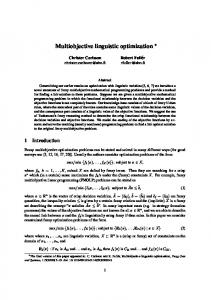
Fig. 2. Layout of the network (adapted from Jowitt and Xu 1990, © ASCE); node IDs inside the circles and pipe IDs
The results of the multiobjective optimization are Pareto fronts, which can be plotted in a graph with the total cost Ctot on the x-axis and the daily leakage volume W L on the y axis. In this context, it should be noted that, in the absence of pipes to design (npd ¼ 0), the procedure proposed in this work degenerates into a procedure for the optimal location of control valves. In the absence of valves to be placed (npv ¼ 0), the procedure degenerates into a minimum cost design procedure if only the objective function in Eq. (17) is used within the optimization process.
Applications Benchmark Network The applications of this work concern the network in Fig. 2, which is derived from the work of Jowitt and Xu (1990), made up of nn ¼ 25 nodes (of which n ¼ 22 with unknown head and n0 ¼ 3 source nodes with fixed head, i.e., nodes 23, 24, and 25) and np ¼ 37 pipes. Tables 1 and 2 report the features of network nodes and pipes used in this work. Three loading conditions, relative to low, intermediate, and high nodal demands, respectively, were adopted to reproduce the network daily operation as to source heads and nodal demands (Table 1). Each of the operation conditions was assumed to be representative of a Δt ¼ 8-h-long time interval. As to leakage, values of the coefficient CL ¼ 10−8 m0.82 =s and of the exponent nleak ¼ 1.18 were assumed for all the pipes of the network, leading to a daily leakage volume of 2,575 m3 without control valves being installed and isolation valves being closed. The first application concerns the optimal location of control valves in the network and the identification of the isolation valves that have to be closed. The total number of decisional variables was npv ¼ np because all the pipes were assumed to be potential candidates for control valve installation. For this application, one isolation valve was assumed to be already present at each network pipe. The objective functions used within the optimization application were the total number N tot of control valves and the daily leakage volume W L . In particular, N tot is a surrogate for the cost (Jowitt and Xu 1990; Reis et al. 1997; Vairavamoorthy and © ASCE
1—fixed head
1 2 3 4 5 6 7 8 9 10 11 12 13 14 15 16 17 18 19 20 21 22 23 24 25
0 0 0 0 0 0 0 0 0 0 0 0 0 0 0 0 0 0 0 0 0 0 1 1 1
Elevation Loading Loading Loading z (m) condition 1 condition 2 condition 3 18 18 14 12 14 15 14.5 14 14 15 12 15 23 20 8 10 7 8 10 7 10 15 54.5 54.5 54
0.003 0.006 0 0.003 0.018 0.006 0 0.012 0 0.003 0.006 0 0 0.003 0.012 0 0 0.003 0.003 0 0 0.012 55.75 55.45 55.40
0.005 0.01 0 0.005 0.03 0.01 0 0.02 0 0.005 0.01 0 0 0.005 0.02 0 0 0.005 0.005 0 0 0.02 55.90 55.50 55.60
0.006 0.012 0 0.006 0.036 0.012 0 0.024 0 0.006 0.012 0 0 0.006 0.024 0 0 0.006 0.006 0 0 0.024 54.50 54.50 54.05
Lumbers 1998; Pezzinga and Gueli 1999; Pezzinga and Pititto 2005; Araujo et al. 2006; Liberatore and Sechi 2009; Nicolini and Zovatto 2009; Nicolini et al. 2011) and was obtained from Eq. (17) by considering fictitiously Cv ¼ 1 for each control valve independently of the diameter of the pipe where the control valve itself was installed. The minimum desired pressure head was set at 25 m for all network nodes, unlike the work of Jowitt and Xu (1990) where a value of 30 m was considered. The different choice is due to the fact that a lower minimum desired pressure head value makes it possible to better investigate the service pressure lowering effects of isolation valve closure. The minimum V min and maximum V max valve settings were set at 0.001 and 1, respectively. A population of 50 individuals and a total number of 100 generations, corresponding to a total number of 5 × 10³ objective function evaluations, were used for the GA of the hybrid algorithm. The second application concerns the full rehabilitation of the network with the objective to attenuate leakage. In this case, both pipe diameters and valve locations were simultaneously optimized and the isolation valves that have to be closed were also identified. The total number of decisional variables was npd þ npv ¼ 2np because all pipes were deemed to be potential candidates for both pipe replacement and control valve installation. The objective functions used within the optimization application were the total installation cost and the daily leakage volume. The costs of the pipes for unit length and of the control valves used for the optimization are reported in Table 3 as a function of pipe diameter. The table also reports the costs of the isolation valves that were inserted in all the newly installed pipes. The newly installed pipes were assumed to feature a Hazen-Williams coefficient equal to 130 m0.38 =s and
04014059-5
J. Water Resour. Plann. Manage.
J. Water Resour. Plann. Manage.
Table 2. Features of Network Pipes, in Terms of End Nodes, Length L, Diameter D, and Hazen-Williams Roughness Coefficient
Downloaded from ascelibrary.org by University of Exeter on 07/24/14. Copyright ASCE. For personal use only; all rights reserved.
Pipe
Upstream node
Downstream node
Length L (m)
Diameter D (mm)
Hazen-Williams coefficient (m0.38 =s)
23 23 24 25 10 13 14 16 2 3 12 15 17 18 20 19 20 21 21 22 12 11 10 8 8 9 6 22 22 4 5 6 5 7 5 5 6
1 24 14 14 24 24 13 25 1 2 13 16 16 17 18 17 19 20 15 15 15 12 11 12 10 8 8 8 21 3 4 3 6 6 22 7 9
606 454 2,782 304 3,382 1,767 1,014 1,097 1,930 5,150 762 914 822 411 701 1,072 864 711 832 2,334 1,996 777 542 1,600 249 443 743 931 2,689 326 844 1,274 1,115 615 1,408 500 300
457 457 229 381 305 475 381 381 457 305 457 229 305 152 229 229 152 152 152 229 229 229 229 457 305 229 381 229 152 152 229 152 229 381 152 381 229
110 110 105 135 100 110 135 110 110 110 110 125 140 100 110 135 90 90 90 100 95 90 90 110 105 90 110 125 100 100 110 100 90 110 100 110 90
1 2 3 4 5 6 7 8 9 10 11 12 13 14 15 16 17 18 19 20 21 22 23 24 25 26 27 28 29 30 31 32 33 34 35 36 37
Fig. 3. First application: Pareto fronts of optimal trade-off solutions between number N tot of control valves and daily leakage volume W L : (a) results of the hybrid algorithms after 30 and 100 generations and of the traditional NSGAII; (b) results of the hybrid algorithm obtained considering and neglecting the possibility to close the isolation valves
The applications of this work were performed in the MATLAB 2011b environment by making use of a single processor of an Intel Core i7-3520M 2.90 GHz unit.
values of the leakage coefficient CL and exponent nleak equal to 0.6 × 10⁻⁸ m0.82 =s (40% lower than the old pipes) and 1.18 (equal to the old pipes), respectively. The same loading conditions, pressure constraints, and minimum and maximum valve settings were also adopted for the second application. In this case, a population of 300 individuals and a total number of 300 generations, corresponding to a total number of 9 × 10⁴ objective function evaluations, were used.
Table 3. Set of Diameters D, Pipe Costs c for Length Unit, Control Valve and Isolation Valve Costs Cv Diameter identification number 1 2 3 4 5 6 7 © ASCE
D (mm)
c (Euro=m)
Cv control valve (in Euro)
Cv isolation valve (in Euro)
152 229 305 381 457 475 508
49.8 82.6 118.4 190.4 279.3 292.1 315.4
7,488 10,592 14,327 18,728 23,796 25,094 27,570
1,876 3,579 5,804 8,568 11,871 12,733 14,390
Results The Pareto front of optimal solutions obtained after 100 generations by means of the new hybrid algorithm is reported in Fig. 3(a). The front, which presents solutions up to a number of installed control valves N tot ¼ 7, has an asymptotic trend as the number of installed control valves grows. The first solution with N tot ¼ 0 (0 control valves installed) features a value of W L ¼ 2,055 m3 , which is much lower than the value of 2,575 m3 obtained when no control valves are installed and no isolation valves are closed. This leakage reduction effect is due to the closure of some isolation valves in the network. In particular, a significant leakage volume reduction is noticed until the number of installed valves equals 4. For larger number of valves, the decrease in the leakage volume becomes insignificant. The final Pareto front obtained with the new hybrid algorithm is also compared with the Pareto front after 30 generations in the graph in Fig. 3(a). The closeness of the two fronts entails that the new algorithm converges rapidly in terms of number of iterations. The quick convergence is ascribed to the very simple encoding of individual genes that are as numerous as the pipes (np ¼ 37), being only related to the presence of the valves (and not to their settings), and can take on only three integer values.
04014059-6
J. Water Resour. Plann. Manage.
J. Water Resour. Plann. Manage.
Downloaded from ascelibrary.org by University of Exeter on 07/24/14. Copyright ASCE. For personal use only; all rights reserved.
Fig. 3(a) also shows the Pareto front obtained in a benchmark optimization, performed using the traditional NSGAII, where the iterated LP is not embedded, and which then features additional npv × nΔt ¼ 111 genes with respect to the hybrid algorithm to characterize control valve regulation. In this benchmark optimization, 500 population individuals, and 1,000 generations (both larger than in the optimization performed with the hybrid algorithm), which lead to a total number of objective function evaluations equal to 5 × 10⁵ , were used in order to have the same overall computation time as the hybrid algorithm, where a significant computation burden is required by the iterated LP. Fig. 3(a) shows that the Pareto front obtained by means of the new hybrid algorithm dominates that obtained by means of the traditional NSGAII, which also has the drawback of not presenting solutions featuring a number of control valves larger than 2. The worse effectiveness of the traditional NSGAII is due to the bad numerical performance of the fully GA in searching for the optimal control-valve settings besides valve locations. In the hybrid algorithm, the large computation burden associated with the iterated LP is paid back by the consequent improvement in the overall algorithm performance. Once the good numerical performance of the new hybrid algorithm has been highlighted, the evaluation of the correctness of the basic assumption of the new methodology, i.e., that related to taking the presence of isolation valves into account, is now focused on. To this end, Fig. 3(b) reports the comparison of the final Pareto front of the optimization performed by using the hybrid algorithm [as in Fig. 3(a)] and the final Pareto front of an optimization performed by using the hybrid algorithm without allowing for the identification of the isolation valves that have to be closed during the optimization process (i.e., excluding the gene value equal to 2). In the optimization without isolation valves, the algorithm yields solutions that have objective function values close to those obtainable by the algorithms proposed by previous authors, such as Nicolini and Zovatto (2009), up to a number of installed valves N tot ¼ 5. The new algorithm has the advantage of also yielding solutions for N tot > 5. The analysis of Fig. 3(b) shows that the Pareto front obtained considering the closure of isolation valves dominates the other front (obtained without taking account of the presence of the isolation valves). In other words, in order to obtain a certain daily leakage volume reduction, a larger number of control valves has to be installed if isolation valves are not used to contribute to pressure head lowering as well as to facilitate the control valve regulation. For example, Fig. 4 shows the graphical representation of the Pareto front solution derived from the optimization taking account of the presence of the isolation valves and featuring a number of control valves N tot ¼ 3. This solution entails closing the isolation valves present in pipes 3, 4, 5, 10, 15, 20, 26, 29, 32, and 33 and installation of control valves in pipes 1, 8, and 11. The settings of these control valves in the three operation conditions used for the optimization are shown in Fig. 5(a). The graph in Fig. 5(b) reports the pressure heads obtained by the network simulation model in the nodes immediately downstream of the valves in the three operation conditions. This information can be useful for the actual regulation of pressure reducing valves in pipes 1, 8, and 11. The Pareto front of the second application, concerning the rehabilitation of the Jowitt and Xu (1990) network, is shown in Fig. 6(a) and comprises solutions featuring growing values of installation cost Ctot (related to pipe replacement and valve installation) and decreasing values of daily leakage volume W L . The graph in Fig. 6(b) shows the percentages of Ctot associated with valve installations (Cvalves ) and with pipe replacements (Cpipes ) for the various solutions of the Pareto front. The analysis of this graph points out that for low Ctot values, only control valve installations © ASCE
Fig. 4. First application: representation of the solution with N tot ¼ 3 control valves installed (adapted from Jowitt and Xu 1990, © ASCE)
are performed. When Ctot overcomes the threshold value of 141,207 Euro [in correspondence to which there is a discontinuity in the Pareto front in Fig. 6(a)], pipe replacements start to be carried out; the percentage of Ctot associated with valve installations then decreases up to 6%, whereas that associated with pipe replacements increases up to 94%.
Fig. 5. First application: for the solution with N tot ¼ 3 control valves installed: (a) valve settings in the three operation conditions; (b) pressure heads at the nodes immediately downstream of the valves
04014059-7
J. Water Resour. Plann. Manage.
J. Water Resour. Plann. Manage.
Downloaded from ascelibrary.org by University of Exeter on 07/24/14. Copyright ASCE. For personal use only; all rights reserved.
Eq. (19) can be easily generalized to take account of different values of T for pipes and valves. Even if W L is bound to grow in time due to pipe deterioration (Farley and Trow 2003), it is kept constant herein for simplification purposes. As to the water unit cost, the values cw ¼ 0.3, 0.6, 1.0 Euro=m3 were adopted. As an example, the graph in Fig. 6(b) reports the trend of Coverall as a function of Ctot for the three cw values, obtained by evaluating Coverall through Eq. (19) for all the solutions of the front in Fig. 6(a). This graph shows that, for cw ¼ 0.3 Euro=m3, the minimum of Coverall lies in correspondence to the solution featuring an installation cost Ctot ¼ 131,326 Euro; as cw grows, the minimum shifts rightwards in the Ctot axis. As the water unit cost grows, it is then convenient, in terms of Coverall , to carry out more numerous interventions, in terms of control valve installations and pipe replacements, to rehabilitate the network and, thus, to reduce leakage. These results are in agreement with those obtained by Pezzinga and Pititto (2005) by using a single objective optimization. Nevertheless, the main advantages of the new algorithm proposed in this work lie in that: • It makes it possible to consider the closure of isolation valves as a contribution to leakage attenuation; and • Being based on the multiobjective approach, it enables optimization to be performed keeping the two objectives separate [results in Fig. 6(a)]. As shown above, the postprocessing [Figs. 6(b and c)] then leads to the choice of the final solution.
Conclusions
Fig. 6. Second application: (a) Pareto front of optimal trade-off solutions between installation costs Ctot and daily leakage volume W L ; for each solution; (b) percentages of Ctot associated with the installation of valves and with pipe replacement; (c) assessment of the overall costs Coverall for different water unit cost; costs are in Euro
For the choice of the solution to adopt in the rehabilitation phase, it is possible to make economic considerations. The couple of values Ctot − W L featured by the generic solution makes it possible to evaluate the overall cost of the construction, comprising both the total installation cost (associated with the installation of pipes and valves) and the cost of the leakage volume distributed all over the useful life T of the construction. This overall cost Coverall can be assessed, as an example, through the following relationship: Coverall ¼ Ctot þ
T X 365cw W L t¼0
ð1 þ rÞt
ð19Þ
where cw = water unit cost and r = capital recovery factor. At this stage, the value r ¼ 0.04 was used. As to the useful life of the construction, a single value T ¼ 60 years was assumed for both pipes and valves for simplification purposes. However, © ASCE
In this paper, a multiobjective algorithm for the combined optimization of pipes and control valves for leakage reduction in water distribution networks was presented. The algorithm makes it possible to explore the trade-off between installation costs (or a surrogate for them) and daily leakage volume. With respect to the other algorithms in the scientific literature, the applications pointed out the main advantage of the new algorithm, which lies in the fact that it considers the presence of isolation valves in the network, which can be closed in order to contribute to leakage attenuation and to eliminate water paths around the control valves, thus facilitating control-valve regulation. Another interesting aspect of the algorithm is its hybrid nature, which makes it possible to split the research space between two inner algorithms: a GA, useful to search for the suitable pipe replacements, control valve installations and isolation valve closures, and the LP, aimed at searching for the optimal settings of the control valves installed. This hybrid nature makes the algorithm very efficient in comparison to traditional GAs in facing the optimization problem considered in this paper. A practical criterion based on a long-term economic analysis, which can be practically adopted to select the most convenient solution within the Pareto front of solutions yielded by the algorithm, was also presented in the paper. Two final caveats have to be made as far as the use of the algorithm herein presented is concerned. The installation and suitable regulation of control valves and the closure of isolation valves have the effect of lowering the network service pressure to the lowest values that guarantee the full satisfaction of user demands. It is then recommended that the valves be opened during such critical operation scenarios as those related to segment isolation or hydrant activation in order to restore the network redundancy and thus prevent compromising the service to users. Sometimes operating the control and isolation valves can also alter water paths in the network. In the presence of multiple tanks supplying water to users, this could entail variations in the emptying/filling processes of these devices. In the applications of this work, this aspect was not investigated
04014059-8
J. Water Resour. Plann. Manage.
J. Water Resour. Plann. Manage.
because it was not the focus of the paper. Nevertheless, applications to real case studies could require this aspect to be taken into account explicitly.
Appendix I. Matrixes of the Iterated LP Algorithm Matrixes M1 ðn; nÞ, M2 ðn; nv Þ and M3 ðn; 1Þ are calculated through the following relationships: M1 ¼ A21 B11 NA12 jA21 j jA j diagðCLLÞdiagðPnleak −1 Þ 12 ; 2 2 M2 ¼ αA2pv Bpvpv diagðV α−1 ÞdiagðApv0 H0 þ Apv2 HÞ; � � jA j jA10 jðH0 − z0 Þ − jA12 jz M3 ¼ 21 diagðCLLÞdiagðPnleak −1 Þ 2 2
Downloaded from ascelibrary.org by University of Exeter on 07/24/14. Copyright ASCE. For personal use only; all rights reserved.
þ
At the end of the iterations, the lowest value of W L;j is saved, along with the control-valve settings that yield it. The relaxation coefficient at Step 6 has to be introduced in order that a control valve setting vector V, which leads to minimum pressure constraints of Eq. (11) being met at network nodes, is obtained for iteration iter þ 1 starting from the control valve setting vector of iteration iter. Should the relaxation coefficient not be used, there would be no guarantee to have a feasible vector V iterþ1 starting from a vector V iter. The relaxation coefficient is set equal to the highest value (within a pre-fixed range ½Ωmin ; Ωmax �) that does not prevent the minimum pressure constraints of Eq. (11) from being met. As to the iterative method of relaxation, a preliminary analysis performed on various networks showed that the values 0.001, 0.1, and 10 can be assigned to parameters Ωmin , Ωmax , and nconit . These values lead to a good numerical performance even when a large number of control valves is installed in the network.
þ d − αA21 B11 NA12 H þ αA2nv Bnvnv ðAnv0 H0 þ Anv2 HÞ þ ð1 − αÞA21 B11 NA10 H0
ð20Þ
where matrixes Bpvpv and Bnvnv are derived from matrix B11 by considering the rows and the columns associated with the pipes fitted with control valve and lacking of control valve, respectively. Matrixes Apv0 and Apv2 are derived from matrixes A10 and A12 respectively, by considering the rows associated with the pipes fitted with control valve. Matrixes Anv0 and Anv2 are derived from matrixes A10 and A12 respectively, by considering the rows associated with the pipes lacking of control valve. In Eq. (2), vectors V and H and matrix N are relative to iteration iter and vector P (np × 1) is yielded by the following relationship P¼
jA10 jðH0 − z0 Þ þ jA12 jðH − zÞ 2
ð21Þ
Appendix II. Steps of the Iterated LP Algorithm Optimization of the control-valve settings is performed according to the following steps: 1. Set iteration number iter ¼ 0 and initial values for the controlvalve settings (as an example equal to V max —fully open control valves); construct vector V 1 of control-valve settings; 2. Set iter ¼ iter þ 1; the vector of control-valve settings is V iter comes from the previous step; 3. Construct matrix M; apply an hydraulic simulator (e.g., Todini and Pilati 1988) to solve Eq. (6) and derive vector Hiter of nodal heads; evaluate network leakage volume W iter L;j through Eq. (5); 4. Evaluate vector E of Eq. (15) and matrixes M1 , M2 and M3 of Eq. (16) as explained in Appendix I; 5. Solve the LP with Eq. (14) as objective function, Eqs. (11), (13), and (16), as constraints, and vectors H and V as decisional variables; 6. Calculate vector V iterþ1 of the valve settings at the new iteration from vector V of current control-valve settings through the following method of relaxation V iterþ1 ¼ V iter þ ΩðV − V iter Þ
ð22Þ
with Ω being the relaxation coefficient, for which details are given below; and 7. If a stopping criterion [such as the maximum number nconit of consecutive iterations without improvements in the objective function reported in Eq. (5)] is met, stop iterations. Otherwise, repeat Steps 2–7. © ASCE
References Ali, M. (2014). “Knowledge-based optimization model for control valve locations in water distribution networks.” J. Water Resour. Plann. Manage., 10.1061/(ASCE)WR.1943-5452.0000438, 04014048. Alvisi, S., Creaco, E., and Franchini, M. (2011). “Segment identification in water distribution systems.” Urban Water J., 8(4), 203–217. Araujo, L. S., Ramos, H., and Coelho, S. T. (2006). “Pressure control for leakage minimisation in water distribution systems management.” Water Resour. Manage., 20(1), 133–149. Campisano, A., Creaco, E., and Modica, C. (2010). “RTC of valves for leakage reduction in water supply networks.” J. Water Resour. Plann. Manage., 10.1061/(ASCE)0733-9496(2010)136:1(138), 138–141. Campisano, A., Modica, C., and Vetrano, L. (2012). “Calibration of proportional controllers for the RTC of pressures to reduce leakage in water distribution networks.” J. Water Resour. Plann. Manage., 10.1061/ (ASCE)WR.1943-5452.0000197, 377–384. Creaco, E., and Franchini, M. (2012). “Fast network multi-objective design algorithm combined with an a posteriori procedure for reliability evaluation under various operational scenarios.” Urban Water J., 9(6), 385–399. Creaco, E., and Franchini, M. (2013a). “A new algorithm for the real time pressure control in water distribution networks.” Water Sci. Technol.: Water Supply, 13(4), 875–882. Creaco, E., and Franchini, M. (2013b). “Low level hybrid procedure for the multi-objective design of water distribution networks.” Proc., 12th Int. Conf. on Computing and Control for the Water Industry, CCWI2013, Elsevier, Italy. Creaco, E., Franchini, M., and Alvisi, S. (2010). “Optimal placement of isolation valves in water distribution systems based on valve cost and weighted average demand shortfall.” Water Resour. Manage., 24(15), 4317–4338. Deb, K., Pratap, A., Agarwal, S., and Meyarivan, T. (2002). “A fast and elitist multiobjective genetic algorithm NSGA-II.” IEEE Trans. Evol. Comput., 6(2), 182–197. Di Nardo, A., Di Natale, M., Santonastaso, G. F., Tzatchkov, V., and Yamanaka, V. H. (2013). “Water network sectorization based on genetic algorithm and minimum dissipated power paths.” Water Sci. Technol.: Water Supply, 13(4), 951–957. Farley, M., and Trow, S. (2003). Losses in water distribution networks, IWA, London. Haghighi, A., Samani, H. M. V., and Samani, Z. M. V. (2011). “GA-ILP method for optimization of water distribution networks.” Water Resour. Manage., 25(7), 1791–1808. Jourdan, L., Corne, D., Savic, D., and Walters, G. (2004). “Hybridising rule induction and multi-objective evolutionary search for optimising water distribution systems.” Proc., Fourth Int. Conf. on Hybrid Intelligent Systems, IEEE Computer Society, Los Alamitos, CA, 434–439.
04014059-9
J. Water Resour. Plann. Manage.
J. Water Resour. Plann. Manage.
Downloaded from ascelibrary.org by University of Exeter on 07/24/14. Copyright ASCE. For personal use only; all rights reserved.
Jowitt, P. W., and Xu, C. (1990). “Optimal valve control in water distribution networks.” J. Water Resour. Plann. Manage., 10.1061/(ASCE) 0733-9496(1990)116:4(455), 455–472. Liberatore, S., and Sechi, G. M. (2009). “Location and calibration of valves in water distribution networks using a scatter-search meta-heuristic approach.” Water Resour. Manage., 23(8), 1479–1495. Nicolini, M., Giacomello, C., and Deb, K. (2011). “Calibration and optimal leakage management for a real water distribution network.” J. Water Resour. Plann. Manage., 10.1061/(ASCE)WR.1943-5452.0000087, 134–142. Nicolini, M., and Zovatto, L. (2009). “Optimal location and control of pressure reducing valves in water networks.” J. Water Resour. Plann. Manage., 10.1061/(ASCE)0733-9496(2009)135:3(178), 178–187. Olsson, R. J., Kapelan, Z., and Savic, D. A. (2009). “Probabilistic building block identification for the optimal design and rehabilitation of water distribution systems.” J. Hydroinform., 11(2), 89–105. Pezzinga, G., and Gueli, R. (1999). “Discussion of optimal location of control valves in pipe networks by genetic algorithms.” J. Water Resour. Plann. Manage., 10.1061/(ASCE)0733-9496(1999)125:1(65), 65–67. Pezzinga, G., and Pititto, G. (2005). “Combined optimization of pipes and control valves in water distribution networks.” J. Hydraul. Res., 43(6), 668–677.
© ASCE
Puust, R., Kapelan, Z., Savic, D. A., and Koppel, T. (2010). “A review of methods for leakage management in pipe networks.” Urban Water J., 7(1), 25–45. Raad, D., Sinske, A., and van Vuuren, J. (2009). “Robust multi-objective optimization for water distribution system design using a metametaheuristic.” Int. Trans. Oper. Res., 16(5), 595–626. Reis, L. F., Porto, R. M., and Chaudhry, F. H. (1997). “Optimal location of control valves in pipe networks by genetic algorithm.” J. Water Resour. Plann. Manage., 10.1061/(ASCE)0733-9496(1997)123:6(317), 317–326. Talbi, E. G. (2002). “A taxonomy of hybrid metaheuristics.” J. Heuristics, 8(5), 541–564. Todini, E., and Pilati, S. (1988). “A gradient algorithm for the analysis of pipe networks.” Computer application in water supply, B. Coulbeck and O. Choun-Hou, eds., Vol. I, John Wiley & Sons, London, 1–20. Vairavamoorthy, K., and Lumbers, J. (1998). “Leakage reduction in water distribution systems: Optimal valve control.” J. Hydraul. Eng., 10.1061/ (ASCE)0733-9429(1998)124:11(1146), 1146–1154. Walski, T. M., Chase, D. V., Savic, D. A., Grayman, W., Beckwith, S., and Koelle, E. (2003). Advanced water distribution modeling and management, Haestad Press, Waterbury, CT. Wang, Q., Savic, D. A., and Kapelan, Z. (2014). “Hybrid metaheuristics for multi-objective design of water distribution systems.” J. Hydroinform., 16(1), 165–177.
04014059-10
J. Water Resour. Plann. Manage.
J. Water Resour. Plann. Manage.