AbstractâInclusion of voltage support distributed generation. (VSDG) can reinforce the ... may occur during multiple VSDG inclusion in the network and presents ...
676
IEEE TRANSACTIONS ON ENERGY CONVERSION, VOL. 20, NO. 3, SEPTEMBER 2005
Multiple Distributed Generators for Distribution Feeder Voltage Support M. A. Kashem, Senior Member, IEEE, and Gerard Ledwich, Senior Member, IEEE
Abstract—Inclusion of voltage support distributed generation (VSDG) can reinforce the feeder voltage of distribution networks, especially in rural/remote areas where voltage dip and frequent blackouts are significant concerns for power utilities. However, installation of multiple distributed generators within a distribution grid system may introduce technical problems in network operation and control, including control interaction and/or voltage instability. This paper addresses the network issues that may occur during multiple VSDG inclusion in the network and presents analytical models and solutions to develop design criteria of VSDG installation in the networks. Voltage sensitivity of lines is investigated and the effect of DG real (P) and reactive (Q) power injections with Q priority is developed for optimal use of VSDG in correcting the network voltage. Interaction among VSDG controllers has been explored and a generalized model is presented to analyze this interaction between any number of VSDGs in the network. The model is tested on a sample VSDG system and test results are presented. The issue of which VSDG must be started recognizing the costs of starting is addressed using an inverse definite minimum time (IDMT) model. A prioritization and coordination scheme for start discrimination of multiple VSDGs is proposed which avoids hunting between multiple generators. Index Terms—Dynamics, eigenvalues and eigenfunctions, power distribution, power generation control, sensitivity, voltage control.
I. INTRODUCTION
T
HERE is a growing interest in distributed generation (DG) as an alternative for supplying electric power to customers. Worldwide, the current trend of electricity market deregulation is leading to continuous growth in the number of DGs connected to utilities’ distribution networks for a number of reasons [1]: i) electricity market rules encouraging competition and simplified connection, ii) advances in new technologies, and iii) increasing system capacity needs. Both electric utilities and customers are users of DG as both can gain advantages. For a utility, DG could be used as an additional option to meet load growth and to relieve transmission constraints. From the perspective of the end-user customers, DG could offer higher power quality and overall reliability at a competitive power cost. In order to maximize the DG benefits, DGs need to use the existing utilities’ transmission and distribution systems to transfer their generated power from one location to another. However, with the aim of effectively integration of DGs into utilities’ networks, several requirements, such Manuscript received September 11, 2002; revised May 9, 2003. This work was supported by Queensland Electricity Transmission and Distribution (QETD). Paper no. TEC-00205-2002. M. A. Kashem is with the School of Engineering, University of Tasmania, Hobart TAS 7001, Australia. G. Ledwich is with the School of Electrical and Electronic Systems Engineering, Queensland University of Technology, Brisbane 4001, Australia. Digital Object Identifier 10.1109/TEC.2004.832090
as voltage regulation, loss of main protection, and the sustainability of DGs following disturbances on the associated network need to be satisfied. Selected use of DG can provide system benefits including improved power quality, reduction in central generating station reserve requirements, and reactive power support [1]. Grid-supported DGs can provide the transmission capacity release, reduction in network losses, and avoidance or postponement of high investment costs for network upgrades. These benefits could be quantified by comparing DG with the traditional alternatives of central generation and transmission expansion. DG is a distinct change from the traditional central plant model for power generation since it delivers electrical power directly to the distribution network or to the place where the power is consumed, without using the transmission system. Dugan et al. [2] have discussed operating conflicts and voltage regulation issues that often arise from the application of distributed generation on distribution systems. Donnelly et al. [3] have addressed the impacts of distributed generation upon the bulk transmission system stability and analyzed transmission system transient and small-signal stability through the use of extensive case studies. In [4], Kim et al. proposed a voltage regulation coordination method of distributed generation system at which distribution system voltage regulation is coordinated by controlling its reactive power output according to its real power output. Girgis et al. [5] have explored the effect of DG inclusion on coordination of protection devices such as fuse-fuse, fuse-recloser, and relay-relay and attempted to identify coordination-margin or safety margin through coordination graphs. The dynamics of distribution networks with distributed generation for different penetration scenarios have been discussed in [6]. In [6], the impact of DG is assessed using both eigenanalysis and individual channel analysis and design (ICAD) for small-signal analysis, and nonlinear time-domain simulations for transient stability analysis. In this continuous time analysis of multimachine scenarios, the participation of the generator subsystems: rotor dynamics, synchronous machine, AVR/exciter, and governor/turbine in the oscillation modes has been examined to detect the degree of interaction. In this paper, optimal use of voltage support distributed generation (VSDG) to support voltage in distribution feeders is analyzed through in terms of voltage response and voltage sensitivity of lines. A mathematical model is developed to analyze the dynamics of multiple VSDGs, which can be used to formulate design criteria of multiple VSDG installation in the network. This work examines voltage-control interaction rather than angle stability and is thus more relevant to inverter-based VSDG. The effect of start penalties with multiple DGs is discussed and the guidelines for prioritization and coordination of multiple VSDGs are proposed.
0885-8969/$20.00 © 2005 IEEE
KASHEM AND LEDWICH: MULTIPLE DISTRIBUTED GENERATORS FOR DISTRIBUTION FEEDER VOLTAGE SUPPORT
677
II. VOLTAGE SENSITIVITY ANALYSIS The electrical distribution network is usually designed to satisfy customers’ demands in maintaining accurate voltage and frequency levels. Voltage drops in lines from distribution substation to customer points are unavoidable. However, the designers aim to limit this drop by redesigning and restructuring the networks and reconfiguring the feeders and loads. By analyzing the voltage sensitivity of lines, the weakness of network voltage support may be identified and opportunities for improvement with real and/or reactive compensation through external active/passive elements can be examined. An expression for voltage sensitivity can be derived from the Thevenin equivalent of a distribution network looking from the connection point of a DG. A generator can be modeled with a passive element provided that the direction of power flows remains the same. The DG can be represented as a negative variable conducif it is used for real power injection and a variable tance if it is used for reactive power injection. The susceptance whole network can be represented as the Thevenin equivalent at and Thevenin the DG connection having a Thevenin voltage . At the DG connection, the admittance and the load is . The voltage of the bus is can be calculated as shown in the voltage sensitivity ratio equation at the bottom of the page. Equation (1) is developed to determine the existing voltage sensitivity of lines without VSDG contribution. If all of the network parameters are known, then the ratio of voltage sensitivity can be calculated from the and will be zero if our above expression. The values of investigation variations around a DG injection of zero real and zero reactive power. For this case, (1) will give voltage sensitivity around the initial DG operating point which is the easiest computation and usually adequate for a range of loading. An alternative approach is to compute the variation in voltage for small injections from the DG. In all cases, the value of sensitivity would approximately be equal to that given by (1), shown at the bottom of the page, if other parameters are constant. The analytical method may be suitable for further analysis. Alternatively, the incremental power injection method is more suitable for industrial applications, as it is easy to implement and can be used to compute the sensitivity on the DG spot at any time. If maximum permitted change of open-circuit voltage caused by the load is limited to about 6% [7], then the limited admittance of the system load implies that the effect on voltage sensitivity is quite small. Therefore, the Thevenin equivalent impedance and network line parameters basically control the voltage sensitivity. Voltage sensitivity can be calculated during DG commissioning or using offline simulation and the same sensitivity may be used for any system loading at any time of the day, as the impact of load on sensitivity has been found to be very small in all cases studied to date.
Fig. 1. Voltage sensitivity for distributed load.
A. Effectiveness of VSDG Injection and Voltage Sensitivity Sensitivity analysis is performed on a sample distribution system with a VSDG at the end of the line to investigate the relation between the line characteristics and network voltage. To demonstrate the relation, three cases of line parameters are , and iii) R X (where considered which are i) R X, ii) R and X are the line resistance and reactance, respectively). Real and reactive injections by VSDG are varied from zero to three times the total load in the network. The solution for the voltage on the feeder with distributed loads (modeled as admittances) is obtained from the admittance matrix. The results are reported in Fig. 1, which shows the voltage sensitivity. It is , reactive power (rather than real power) found that if injection will be most effective to improve the voltage profile. ), capacitive support will be Whereas for high R (i.e., least effective and real power injection will help appreciably to support voltage and improve voltage profile. For low X/R ratio of line (i.e., X R), a distributed generator needs to be operated with higher proportion of P for effective voltage control. However, for high X/R ratio (i.e., X R), VSDG is best operated with higher proportion of Q for effective voltage control. High P effectiveness involves high fuel cost, because P is associated with fuel and it will give high pf solution for VSDG. For high Q effect, fuel injection will be low and it will give a low pf solution. Low pf solution with VSDG is always preferred as Q injection is almost free of operating cost. Therefore, more emphasis should be given to injection of reactive power Q rather than real power P to improve voltage profile. Fig. 2 shows one algorithm of VSDG power generation, based on voltage sensitivity. Rural distribution is typically low X/R and needs high pf correction.
(1)
678
IEEE TRANSACTIONS ON ENERGY CONVERSION, VOL. 20, NO. 3, SEPTEMBER 2005
III. EFFECTIVE DG OPERATION AND CONTROL Supervisory DG coordination in distribution networks requires a measurement system for its effective and efficient operation and control. It can be built with sophisticated communication systems and interconnected with distribution grid controls as a part of the distribution automation with DG. A communication and control scheme could be developed from the distribution substation to all distributed generators. A smart controller (designed for an automated distribution system with various controlled strategies) or an intelligent computer in the distribution substation could monitor and control all DGs’ activities through communication and control links. The DG would be switched on or off depending upon the net generation and voltage/current level monitored by supervisory control and data acquisition (SCADA). As there is a high cost involved in the design and implementation of such a distribution automation system, it may not be suitable for long-distance rural/remote networks. Therefore, it is desirable to determine if optimal operation and control of DG using local measurements is feasible, without using a communication scheme for interconnection. A. Voltage Response of VSDG and Voltage-Control Scheme The VSDG may be controlled based on the voltage level at the point of VSDG connection. The lower and upper voltage thresholds should be defined from offline studies. If the voltage level is equal to or below the lower threshold for a defined period, VSDG must be switched on. On the other hand, if the value is equal to or above the upper threshold for a defined period, VSDG operation needs to be stopped. Voltage-control schemes are developed based on voltage measurement at the connection point. These schemes give results for the distributed load on the feeder which met the desired objectives. In voltage-control model, a VSDG controller is designed using the concept of controller while the generator/motor response is modeled as a lowpass filter to represent the time constants of the system. Specific issues, such as angle stability, are not covered by this analysis. The concept of VSDG controller design is that changing the fuel injection will vary the real power while changes in field excitation will vary the reactive power from the VSDG. Equation (2) shows how the voltage error is controlled by the controller (2) , , and are the actual voltage where of VSDG connection and prespecified reference voltage to be achieved by VSDG, respectively. and are the proportional and integral constants, respectively. is the error voltage and is the controller-generated signal. Voltage sensitivity analysis for real and reactive injection is individually performed at the connection point of VSDG. Voltage sensitivity at this point is observed by injecting a maximum amount of real and reactive power individually from a small source. The ratio of voltage sensitivity to real and reactive injection for a given system can be , where is the ratio of defined as sensitivity of voltage to real power and reactive power of VSDG.
Fig. 2.
Voltage-sensitivity-based VSDG power generation.
For the steady-state condition, the relationship between optimum where there is real and reactive generations ratio is zero fuel cost. The maximum value of P generation at a given , where is the size sensitivity is of VSDG (kilovolt-amperes). This is the optimal use of a given generator under the assumption of low fuel cost. The operating point of VSDG is determined from the sensitivity ratio of the system and VSDG is operated for maximum voltage improvement. The sensitivity ratio is used in the design of the PQ controller to guide the P and Q generation. Sensitivity ratio can be measured by using the procedure discussed earlier. As shown to maintain in Fig. 2, VSDG can be operated on the line the same sensitivity, where is the maximum sensitivity ratio. For a low level of voltage correction, some classes of VSDG can be operated in the line OQ to generate reactive power from Q . However, for high correction with increased demand, to VSDG will be operated with maximum voltage sensitivity. The to by reducing the operoperating point is shifted from ating angle slowly. Studies have found that for the same voltage specification, distributed generation with real and reactive injection (DG-PQ) using Q priority or DG-QPQ can drastically reduce fuel and energy requirements compared to the amount required by proportional use of real and reactive power in DG-PQ if there are no constraints for high Q operation on the generator. It is advantageous compared to the capacitor in that it has the capability to generate various combinations of real and reactive generation at different times of the day as per customer demands. B. Sample Cases A 120-km three-phase distribution system has been modeled km. This type with line impedance of long length of lines is common in the sparsely populated area of Western Queensland. The source voltage is assumed kV and the source Thevenin impedance is . A distribution transformer with voltage regulator facility is connected at the beginning of the feeder. A voltage regulator is also connected in the feeder at 18.95 km far from the source. Two identical rotary VSDGs, each 200 kVA, are installed on the backbone of the network to investigate voltage improvement and network dynamics. The voltage of this system is calculated by using the technique sensitivity developed in Section II and found as 0.861. DG1 and DG2 are connected at 107.4 km and 69.5 km from the source, respectively. The network status with VSDGs has been examined for light, medium, and heavy load conditions and results are graphically reported in Figs. 3 and 4. For a light load of 400 kVA,
KASHEM AND LEDWICH: MULTIPLE DISTRIBUTED GENERATORS FOR DISTRIBUTION FEEDER VOLTAGE SUPPORT
Fig. 5.
Fig. 3. Voltage profile for low, medium, and heavy loads.
679
Network model with multiple VSDGs at different locations.
and/or installing them far enough from each other. Also, VSDG may create oscillatory waveforms due to low inertia and angle stability. Proper excitation damper design may be able to stabilize VSDG in this situation. Voltage interaction of VSDGs has been analyzed in the following subsection and design criteria have been established. This study has investigated longer-term dynamic interaction of voltage controller assuming the angle has reached its steady state. The following analysis has been performed in continuous time domain assuming angle transients have been settled and, therefore, it only gives an indication of interaction. Short-term angle stability interaction can be performed following the techniques discussed in [6]. A. Mathematical Model of VSDG Interaction
Fig. 4.
Voltage at feeder-end and DG power generation for various loads.
DGs are not required to operate. However, for a medium load of 800 kVA, DGs are operated to inject reactive power only as DG-Q mode. DG operation has turned to DG-PQ mode to inject real and reactive powers for a typically heavy load of 1025 kVA. In this mode, DGs operate at the line of maximum voltage sensitivity of the line. Fig. 4 shows a steady-state voltage at feeder-end and DG power injections for these loading conditions. It is noted that there is a finite transient at the network while changing the network load suddenly. IV. INTERACTION AND OSCILLATION AMONG MULTIPLE DGS Multiple VSDGs, installed in close proximity, may work in opposition when controlling the local network voltage leading to oscillation or excessive circulating current. When installed at a considerable distance from each other, their local network voltages or connection point voltages have not much impact on each other due to the line voltage-drop and consumer loads between them. Interaction between distributed generators may be a concern for voltage correction by multiple VSDGs. Instability between VSDG controllers may be avoided by designing stable VSDG controllers (especially an integral part of the controller)
Rotary machines, such as synchronous generator and induction generator, exhibit slow response in voltage control and motor transients compared to an inverter interface VSDG. These generators can be represented as constant voltage sources in steady state. An inverter-type VSDG (such as PV, fuel cell, or microturbine) is able to respond in milliseconds if required and offers very fast response to correct transients. Inverter interface VSDG requires high-speed current conversion and can be treated as a current source. Due to the nature of past response of inverter interface VSDGs; the probability of interaction caused by them is higher compared to rotary-type VSDG. Therefore, this study has investigated the interaction for inverter interface VSDG only. Assume a three-phase radial distribution system consists of a single feeder with distributed load and number of distributed generators connected at different locations in the feeder. The network has been modeled by considering the total load in a line section lumped each half at both sides of the line section. The main supply at the connection of the network is modeled as a Thevenin equivalent. The Thevenin voltage is assumed the same as the substation voltage and Thevenin impedance is obtained from the short-circuit megavolt-ampere level at that point. Each VSDG is modeled with a voltage source behind constant impedance. Fig. 5 represents the model of the network that consists of number of line section, number of VSDGs connected at different locations, number of bus voltages, and number of loads generated from distributed loads along the line sections. The model has the flexibility that if any of the VSDG position is moved along the feeder section, the line impedances, loads, and connection voltages can be readjusted. The dynamics of VSDG controllers can be observed by relocating the DG positions. Bus voltage and current of the above system are related as follows: (3) Equation (3) can be expanded for the whole system and bus voltages can be computed from matrix inversion and multiplication.
680
IEEE TRANSACTIONS ON ENERGY CONVERSION, VOL. 20, NO. 3, SEPTEMBER 2005
After rearranging, the VSDG connection voltages will appear as in the form of (4)
By transforming s-domain to time-domain, (7) becomes (8) The controller model of th VSDG may be written as
(9) The matrix-equation for controller model of multiple VSDGs will be (10)
(4) where and are the connection voltages and DG currents of DG1, DG2 DGn, respectively. The “C” terms are the constant terms which are not dependent on DG currents and the “K” terms are the coefficients of DG currents. The changes in connection voltages of VSDGs depend on the changes of DG currents, which can be calculated as
and are the diagonal matrices representing s, where , s, and s of all VSDGs, respectively. Equation (6) can be written as (11) Writing (10) and (11) as a matrix, we get (12) , where the The above equation is in the form of is and is the number of VSDGs. The size of coefficient-matrix [A] is (13) Equation (13) can be used for eigenvalue analysis to predict the voltage dynamics caused by VSDGs. As the above model is developed in continuous time domain, eigenvalues close to zero will indicate a high degree of interaction by VSDG giving slow convergence.
(5)
Equation (5) can be written in compact form as (6) The VSDG controller has been designed from the concept that changing the connection voltage of VSDG will vary the VSDG current injection. It is assumed in this analysis that the VSDGs are connected to the distribution grid through an inverter interface and that the VSDG controllers are designed to inject current at a designed pf with value derived from voltage error. controller while the genThe control design is basically a erator/motor response is modeled as a lowpass filter. The current controller has been designed with a finite bandwidth that is used to represent the connection inductance and line inductance. The VSDG controller can be written in s-domain as (7) where is the bandwidth constant, and portional and integral gain factors.
and
are the pro-
B. Test Results of Developed Model The developed model for multiple VSDGs has been tested for two VSDGs installed in the network and Appendix A shows the modeling of VSDG interaction between two VSDGs. The network parameters used in Section II have been used for this test. Two VSDGs, each with 100 kVA, have been considered for this study. Eigenvalue analysis has been performed and the voltage interaction caused by VSDGs has been investigated as affected by the separation distances between VSDGs and altering overall system loading. Fig. 6 shows the changes of smallest eigenvalue and different sepafor different controller time constants ration distances between VSDGs. DG2 has been kept fixed at its original position (25 km apart from the distribution substation) and DG1 has been moved from (1 to 24 km) or highest separation (24 km) to lowest separation (1 km). It is seen in the figure that the smallest eigenvalue has become smaller and less stable if the time constant increases or separation distance decreases. Other eigenvalues are irrelevant for the analysis of interaction with continuous time domain. Time constant is inversely related to bandincreases), the width. If the controller bandwidth decreases ( probability of VSDG interaction in the network will increase. Fig. 7 shows the VSDG connection voltages for various separation distances. As DG2 is kept fixed at its original location, the voltage of its connection point increases when the location of
KASHEM AND LEDWICH: MULTIPLE DISTRIBUTED GENERATORS FOR DISTRIBUTION FEEDER VOLTAGE SUPPORT
681
Fig. 6. Eigenvalues of VSDG interaction for various separation distances (k = 15 and k = 100). Fig. 8. VSDG start with time delay.
Fig. 7. Voltages at connection points of VSDGs for various separation distances (T = 100).
DG1 is moved and brought closer to DG2. The connection point of DG1 is changing along the line from upstream to downstream and, therefore, its connection voltage is decreasing. Eigenvalue analysis has been performed to investigate VSDG interaction for different loading conditions. DG1 and DG2 are kept fixed at their original locations and the total system load has been changed from minimum to maximum. It was seen that changes of eigenvalues were very small for the load variation. Therefore, it was concluded that the degree of load influences on VSDG interaction is very low; however, there is a risk of VSDG interaction if VSDGs are closely located to each other and/or bandwidth constant of the network decreases. V. START PENALTY WITH MULTIPLE DGS VSDG start is an issue for distribution network operators as frequent start-stop may deteriorate network stability and power quality as well as wear and tear on the generator. Also, the consequence of VSDG start has an adverse impact on rural/remote network operation due to a potentially sharp voltage rise in these low capability networks. Operation of multiple VSDGs without
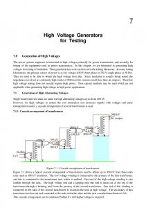
communication will have a greater risk of start penalty due to the fact that the network will have a high probability of maloperation of VSDGs with frequent start-stop. The degree of start penalty of VSDG mostly depends on VSDG technologies and VSDG start/stop costs. When network voltage conditions require instant generation of real and reactive power, PV technology is good but the real power would usually be in use whenever possible and the reactive power would then be the only aspect suddenly changed. But a diesel or gas turbine driven synchronous generator requires a few minutes to run before connecting to the network for synchronization with the network and network loads. These technologies are normally used for peak shaving. The drawback of these technologies is that they can create a transient overvoltage when they are switched onto the network whereas an inverter interface PV and fuel cells can be switched on at the instance of zero-voltage crossing which reduces power-quality problems. If VSDG technologies are designed to start up in response to a voltage constraint, then the VSDG that sees the voltage level equal to or lower than the lower voltage constraint first will start immediately. The decision to start VSDG will be made when the prospective effect of low voltage exceeds the start penalty of VSDG. To avoid/minimize start costs and maloperation of VSDG, the VSDG can be started with a delay and the required delay time may be set with respect to the expected voltage dip of the network. For this purpose, an inverse definite minimum time (IDMT) model is developed in this paper and recommended for defining when a VSDG should start. The proposed inverse definite minimum time model is very similar to the characteristic of IDMT relay [8] and CBEMA curve [9]. We recommend to start VSDG immediately (with a delay of 0.5 s to avoid network transients) if the voltage dip of the network at VSDG connection is 10% or higher. VSDG should have a delay during its start if the voltage dip is below 10%. For a sample model shown in Fig. 8, VSDG will wait for 10 s for voltage dip of 6% and it will wait for 5 s for a voltage dip of 7%. Using inverse
682
IEEE TRANSACTIONS ON ENERGY CONVERSION, VOL. 20, NO. 3, SEPTEMBER 2005
definite minimum time (IDMT) model, VSDG start can be avoided due to the voltage dip caused by sudden load change and/or motor start. Also, the use of the IDMT model will give the tap changer or voltage regulator a chance to response first before starting the VSDG. Technologies with a lower start cost will operate with a lower IDMT curve. VI. PRIORITIZATION AND COORDINATION OF MULTIPLE DGS VSDG priority depends on the need for VSDG operation and voltage level at the VSDG connection point. The determination of VSDG priority during VSDG start-stop should consider the VSDG technology, the predicted time of operation, VSDG location, voltage dip, customer demand, etc. Some VSDG technologies cannot be energized to operate instantaneously at the instant of start as they require some time for warming up and frequency adjustment before operation. The cost for start-stop operation of these technologies can become expensive if the VSDG generation involves frequent start-stop. For the above reason, certain types of VSDG generation will also be costly if the VSDG is operated for short duration of time (with one start). VSDG location plays a role on VSDG prioritization. VSDG could be located in a place where voltage level is always low and poor voltage is seen at most of the time without VSDG. Therefore, high priority should be given for these cases. The purpose of VSDG inclusion is to mitigate the voltage dips and improve voltage level in the distribution network. VSDG prioritization should be scheduled based on the level of voltage dip at VSDG connection or downstream locations where voltage dips are the worst. The voltage dip is related to the customers’ load demands. VSDG coordination is required to operate and control VSDGs effectively and to avoid hunting of starting and stopping. This coordination of which VSDG should start is similar to protection decisions of which breaker should open [8]. Ideally coordination of starting should be centralized but low-cost implementation is feasible using the connection point voltage as the only indicator and improvements are possible if the downstream load is also measured. Through VSDG coordination, VSDGs will be able to correct network voltage on a priority basis. VSDG operation can be coordinated based on the VSDG connection point voltage. Setting the voltage references of separate VSDGs can provide a graduated response to voltage correction. By setting each VSDG voltage threshold, VSDG start-stop can be controlled and prioritization and coordination can be maintained. For a particular loading condition, VSDG connection voltage may become lower than the lower threshold voltage and VSDG will start generation. Again, if the connection voltage goes higher than the upper threshold, it will stop generation. For the case of multiple VSDGs, all VSDGs can be coordinated by fixing the threshold values. Most of the time, voltage at the downstream feeder is lower than that at upstream due to the voltage drop in the feeder. In this situation, VSDG at the extreme downstream will be started and stopped generation earlier than the one next to it, for the same level of threshold values. The schedule of VSDG operations may be altered by changing the VSDG threshold voltages. Introducing time delay in a VSDG system would be an advantage for VSDG coordination. A VSDG controller may be
Fig. 9. Multiple VSDG coordination with time delay.
designed with incorporating time delay for VSDG start as proposed in an IDMT model. The starting decisions for multiple VSDG starts can be well coordinated with this model. Fig. 9 shows VSDG coordination with time delay. In the figure, VSDG starts are coordinated with the help of the IDMT model and set with different time-delay thresholds for start discrimination. In a typical VSDG system coordination shown in Fig. 9, for a 6% of voltage dip, DG1 is operated with a delay of 10 s, DG2 with 30 s, and DG3 with 60 s. In other words, for a voltage dip of 6%, DG2 will be operated after 30 s if DG1 is not operated within 10 s, or DG3 will be operated after 60 s if DG1 is not operated within 10 s and also DG2 is not operated within 30 s. However, if DG1 is operated in 10 s, the network voltage will be improved and voltage dip will be reduced and DG2 or/and DG3 will start only if the connection voltage is still lower than their preset reference voltages or the voltage dip is still higher than the tolerance. For a voltage dip of 10% or higher, VSDG will start immediately [with a typical delay of 0.5 s (used in this study) to avoid network transients]. VII. CONCLUSION Positive and negative impacts of voltage support distributed generation inclusion on utility grid systems have been surveyed and analyzed in this study. The degree of severity of VSDG impact increases with the increase of size and/or number of VSDGs. Voltage sensitivity of lines has been investigated and sensitivity-based VSDG operation has been presented. A design scheme for a VSDG controller based on voltage sensitivity is proposed to correct the network voltage effectively. VSDG operation with Q priority is most economical, as it requires generation of less energy and reduces the fuel requirement to meet the same level of voltage specification, but high levels of compensation on rural lines will require some real generation. A mathematical model of VSDG interaction is presented and VSDG interaction in voltage control is analyzed but does not address angle stability relevant to synchronous machine-based VSDG which can be handled by stabilizer design. Eigenanalysis
KASHEM AND LEDWICH: MULTIPLE DISTRIBUTED GENERATORS FOR DISTRIBUTION FEEDER VOLTAGE SUPPORT
has been conducted to predict the degree of VSDG interaction and develop the design criteria. To avoid dynamic interaction caused by VSDGs, a significant distance should be maintained between VSDG installations. Start penalty with multiple VSDGs has been discussed and an inverse definite time characteristic scheme for VSDG start response is proposed to minimize the total cost associated with VSDG starts. The scheme is developed based on voltage dips in the network which can also be used for multiple VSDG coordination. Prioritization and coordination of multiple VSDGs have been discussed from the viewpoint of voltage dips in the network. Multiple VSDGs coordination can be obtained from proper planning of upper and lower voltage thresholds with time delay during the VSDG start. The following recommendations for implementation of voltage support DGs (VSDG) are made in this study. 1) For low levels of voltage correction, it has been found beneficial for the VSDG to operate with minimum real power injection and change reactive injection from minimum to maximum. At higher levels of voltage correction, it is best to operate the VSDG at full megavolt-ampere rating with real and reactive injection. The VSDG controller needs to increase real injection and decrease reactive injection slowly and will settle at the point of maximum voltage sensitivity. The currently available hardware controller for generators do not have the flexibility to incorporate for generation with priority. A new controller system implemented using programmable logic controller (PLC) or microprocessor technology can be developed to implement this type of cost-effective VSDG operation. 2) The integral part of the VSDG controller has the potential to introduce interaction. A VSDG connected through low inductance and/or VSDG installed in close proximity of another VSDG can contribute to interaction or voltage oscillation. Interaction may become worse during the VSDG start/stop. VSDG interaction may be minimized by designing the VSDG controller with damping characteristics. 3) Start penalty, prioritization, and coordination of multiple VSDGs have the potential to become major issues for network operation with VSDG. This paper has formulated these problems and presented an inverse definite time solution. Network operators require a clear-cut procedure to operate networks with multiple VSDG. This approach could form the basis of developing a standard for a coordination scheme of VSDG.
Fig. 10.
683
Network model with two VSDGs at different locations.
APPENDIX A MODELING OF VSDG INTERACTION FOR TWO DGS CASE The network model with two VSDGs is shown in Fig. A and DG1 and DG2 are connected in the network at bus 1 and bus 2, respectively. The network equation for the network in Fig. 10 is
(A.1) Rearranging (A.1), we can obtain bus voltages at VSDG connections in the form of (A.2)
(A.2) where DG current angles are and
(A.3)
and and are the operating angles of inverter interface is the coefficient matrix of DG currents and is VSDGs. the constant matrix which is not dependent on DG currents. The magnitudes and angles of DG connection point voltages are derived from (A.2) and written, as shown in (A.4)–(A.7) on the bottom of the page. VSDG operating angles are adjusted and VSDG current angles are calculated from (A.3). The voltage angles of VSDG connection points are initiated with zeros and updated with iterating (A.3)–(A.7) until the difference of present and previous update values becomes lower than a prespecified tolerance value.
(A.4) (A.5) (A.6) (A.7)
684
IEEE TRANSACTIONS ON ENERGY CONVERSION, VOL. 20, NO. 3, SEPTEMBER 2005
For this sample VSDG system, the F matrix will become 2 2 and the element of F matrix can be determined from (A.4) and (A.5) by taking derivatives with respect to VSDG currents, , and will also become 2 2 matrices individually. , for these two VSDG cases. The model will become (13) and the eigen study proceeds. REFERENCES [1] E. Poza and T. Ackermann, “Centralised power generation versus distributed power generation: a system analysis,” in Proc. 1st Int. Symp. Distributed Generation: Power System Market Aspects, Stockholm, Sweden, Jun. 11–13, 2001. [2] R. C. Dugan and T. E. McDermott, “Operating conflicts for distributed generation on distribution systems,” in Proc. Rural Electric Power Conf., 2001, pp. A3/1–A3/6. [3] M. K. Donnelly, J. E. Dagle, D. J. Trudnowski, and G. J. Rogers, “Impacts of the distributed utility on transmission system stability,” IEEE Trans. Power Syst., vol. 11, no. 2, pp. 741–746, May 1996. [4] T. E. Kim and J. E. Kim, “Voltage regulation coordination of distributed generation system in distribution system,” in Proc. IEEE Power Engineering Soc. Summer Meeting, vol. 1, 2001, pp. 480–484. [5] J. E. Girgis and S. Brahma, “Effect of distributed generation on protective device coordination in distribution system,” in Proc. Large Engineering Systems Conf. Power Engineering, 2001, pp. 115–119. [6] F. V. Edwards, G. J. W. Dudgeon, J. R. McDonald, and W. E. Leithead, “Dynamics of distribution networks with distributed generation,” in Proc. IEEE Power Engineering Soc. Summer Meeting, vol. 2, 2000, pp. 1032–1037. [7] N. Chapman, “Australia’s rural consumers benefit from single-wire earth return systems,” Transm. Distrib., pp. 56–61, Apr. 2001.
[8] T. Davies, Protection of Industrial Power Systems. New York: Pergamon, 1984. [9] IEEE Recommended Practice for Emergency and Standby Power Systems for Industrial and Commercial Applications, IEEE Std. 446-1987.
M. A. Kashem (A’00–SM’05) was born in Bangladesh in 1968. He received the Ph.D. degree from Multimedia University, Malaysia, in 2001. He has four years’ industrial experience and six years in teaching. Currently, he is a Lecturer at the School of Engineering, University of Tasmania, Australia. His special fields of interests include distributed generation, renewable energy, distribution system automation, power system planning, and artificial intelligence. He has published more than 35 technical papers in these areas.
Gerard Ledwich (M’73–SM’92) received the Ph.D. in electrical engineering from the University of Newcastle, Australia, in 1976. He has been Chair Professor in Electrical Asset Management at Queensland University of Technology, Australia, since 1998. He was Head of electrical engineering at the University of Newcastle from 1997 to 1998. Previously, he was associated with the University of Queensland from 1976 to 1994. His interests are in the areas of power systems, power electronics, and controls. Prof. Ledwich is a Fellow of the Institution of Engineers Australia