Multiple-Input Multiple-Output Wireless Systems - Semantic Scholar
Recommend Documents
developed by the Tennessee Technological University and the Uni- versity of South Florida. Students study, design, fabricate, and test a wireless-based sensor ...
Wireless. Information Systems. Qusay H. Mahmoud and. Hans Weghorn (EdS.) Proceedings of the. 3rd International Workshop on. Wireless Information Systems ...
Telemedicine applications, including those based on wireless technologies span the ... kbps, EDGE 384 kbps) and subsequently to 3G (W-CDMA, CDMA2000, ...
Limitations of 4G Wireless Systems ... wireless networks; 3) Mobile nodes will support a small number of adaptive ... number of supported communication modes and over a range ..... sufficient fidelity to demonstrate the possible benefits of the.
ADM (Amazon Device Messaging);. ⢠SIMPLE ..... exclusively to Kindle Fire devices (which are not the most popular wireless devices). Because of these ...
modeling JALIE over a wired network, we introduce ... peer connectivi@, virtual wireless environment, agent .... The major advantage of using JADE is that it.
Mar 29, 1999 - 4.2 Fixed Points for Mixtures of Fixed and Agile Users . .... i bi p. piSi(t) + N(t), multiuser receivers have been designed for a variety of objectives, ...
Aug 7, 2001 - 4.2 Fixed Points for Mixtures of Fixed and Agile Users . .... known waveforms in addition to independent Gaussian noise, that is Z´tµ âi bi.
by section III on transmission of digital images and video. .... kbps using Dolby AC-2 has been achieved, while MPEG-1 Layer 2 audio (32-256 kbps) or Dolby AC ...
1 We often used PayPal as the payment service. Assuming that both merchant and consumer are PayPal users, we would actually transfer funds from payer to ...
of Engineering, the National Academy of Sciences, and is a foreign member ... American Academy of Arts and Sciences, the Royal Academy of Engineering ...
Mobile, nomadic, and fixed wireless devices form new types of resource- sharing networks called wireless grids.1 This issue of IEEE Internet Comput-.
According to this model, the attributes that drive adoption are: Relative advantage. Consumers are likely to. Wireless Web providers should roll out new services.
eTForecasts1 and Global Mobile2 quoted that in year 2000 Mobile voice use, ... Wireless advertising is becoming a hot topic in the advertising and marketing ...
In future wireless systems, packet transmission will be the dominant type of traffic. ..... communication services as well as to fulfill the technology gaps for future ...
associate editor coordinating the review of this paper and approving it for publication was Dr. ... The second group of applications, dedicated HSWS, however, can ..... authentication server to obtain the authentication secrets. Implementation of ...
Third-generation (3G) mobile and wireless net- ... (EDGE/UWC-136) and two 3G Code Division ..... technology enables higher capacities and spectral effi- ciency ...
Apr 4, 2006 - INVITED PAPER Special Section on Advanced RF Technologies for Compact ... Wireless technologies must play important role for not only.
Mapping (SLM), Bit Error Rate (BER), Complementary Cummulative ... OFDM is a multicarrier modulation technique which splits high-rate data streams into a ...
MEDiSN, a wireless sensor network (WSN) designed to continu- ously monitor the vital signs ... benefits of wireless sensing to physicians. We deployed MEDiSN ...
Engineering, University of Missouri, Rolla, MO 65409 USA (email: ... (email: [email protected]). C. Xiao is with the .... density (PSD) ÌRvv(f) of v(k) is. ÌRvv(f) = ...... http://mathworld.wolfram.com/AppellHypergeometricFunction.html. [19] ETSI
Hong Kong University of Science & Technology. Clear Water Bay, Kowloon, Hong Kong email: feejiang, [email protected]. Sanjay Gupta, senior sta engineer.
backbone for sensor to sensor communication. Additionally, we give an overview of the advantages and disadvantages of existing interconnection ... In wireless mesh networks (WMN) [1], the network nodes are considered to be part of the ...
mitters to permit electrophysiological monitoring during free behavior. .... served by using the wireless telemetry unit (over a bandwidth of 300 Hz to 5 kHz).
Multiple-Input Multiple-Output Wireless Systems - Semantic Scholar
Na koncu smo zbrali Å¡e nekaj nereÅ¡enih problemov v zvezi s sistemi MIMO. ..... [4] V. Tarokh, N. Seshari, R. Calderbank, âSpace-Time Codes for High Data Rate ...
Elektrotehniˇski vestnik 70(4): 234–239, 2003 Electrotechnical Review, Ljubljana, Slovenija
Multiple-Input Multiple-Output Wireless Systems Jan Vcelak1 , Tomaˇz Javornik2 , Jan Sykora1 , Gorazd Kandus2 , Sreˇco Plevel2 1
Czech Technical University of Prague, Faculty of Electrical Eng., Technicka 2, Prague, Czech Republic Joˇzef Stefan Institute, Dept. of Digital Commun. and Networks, Jamova 39, Ljubljana, Slovenia E-mail: [email protected], [email protected], [email protected], [email protected] 2
Abstract. The paper gives an overview of the multiple-input multiple-output (MIMO) systems and discusses their benefits enabling an increase in the system capacity and an increase of system reliability. The former is attained by signal multiplexing and the later by space encoding. The basic algorithms required for a proper operation of the MIMO systems, i.e. channel estimation, equalisation, optimal and suboptimal receivers, are described. In the conclusion, open problems of the MIMO systems are outlined. Key words: multiple-input multiple-output MIMO technique, channel capacity, equalisation, signal detection, space coding
Brezvrviˇcni sistemi z veˇc vhodi in veˇc izhodi ˇ Povzetek. Clanek predstavlja pregled sistemov z veˇc vhodi in veˇc izhodi (sistemi MIMO). S sistemi MIMO poveˇcamo zmogljivost ali zanesljivost prenosa. Poveˇcanje zmogljivosti sistema doseˇzemo z multipleksiranjem signalov, medtem ko zanesljivost sistema izboljˇsamo z uporabo prostorskega kodiranja. V cˇ lanku so opisani osnovni algoritmi, ki so potrebni za delovanje sistemov MIMO: algoritmi za oceno radijskega kanala, izenaˇcevalne tehnike ter optimalni in neoptimalni sprejemniki. Na koncu smo zbrali sˇe nekaj nereˇsenih problemov v zvezi s sistemi MIMO. Kljuˇcne besede: sistemi z veˇc vhodi in veˇc izhodi, sistemi MIMO, zmogljivost kanala, izenaˇcevanje, detekcija signalov, prostorsko kodiranje
1
Introduction
In wireless communication systems, the transmitted signal is distorted by fading and interference. Because of these distortions, the recovery of the transmitted data is difficult or even impossible. The increasing requirements on the quality and data flow in wireless systems call for new approaches to improve the bandwidth efficiency and reliability of the systems. Diversity techniques, like the space, time and frequency ones, are well known techniques to improve reliability of the wireless transmission systems and system resistance against distortions. Among them, the space diversity technique is the most promising one, because it does not require any additional bandwidth and does not introduce additional delays in signal transmission. The space diversity is based on the fact that two signals detached in space exhibit an independent fading Received 21 November 2002 Accepted 17 March 2003
in the radio channel. If antennas are not spaced enough to achieve an independent fading, this can lead to loss in diversity benefits [1]. At first, the space diversity approach was implemented at the receiver. For mobile terminals, this approach was found inappropriate and the multiple antennas were placed at the base station transmitter. The real breakthrough in system reliability and system performance was made by introducing the diversity at the transmitter and receiver side [2]. The antenna diversity is obtained when we utilise multiple antennas at either the transmitter or receiver side. However, for multiple antennas on both ends we can utilise spatial multiplexing of different parallel input streams into the channel. The rich scattering on the propagation environment opens multiple parallel channels on the same frequency band to yield an increase in the capacity [3]. When a training sequence is added to the transmitted signal, the receiver can estimate the channel parameters. In some other case, the transmitter can utilise the feedback information about the channel attenuation from the receiver to configure power distribution of the transmitting antennas. Sending the channel information to the transmitter is inappropriate for fast varying channels, and for that reason methods have been developed where the channel state information is not known at the transmitter. The most sophisticated methods are known as spacetime coding. Two approaches exist for space-time coding. The first one is an extension of the trellis coded modulation [4] (STCM space trellis coded modulation) and the second one is based on block codes [6] (STBC space-time block code). The STCM approach introduces a time and spatial correlation into the signal so it provides a diversity
Multiple-Input Multiple-Output Wireless Systems gain at the receiver and a coding gain over the uncoded signal. The STBC uses the block encoder to achieve diversity and orthogonalisation of the channels [6]. The orthogonal channel allows for a simpler implementation of the receivers. Our paper is a short overview of the MIMO systems. It is organised as follows. At first, we describe the MIMO system and MIMO radio channel. We then summarise some results to show the theoretical capacity of the MIMO systems. We continue with a description of the encoded MIMO systems. Because the knowledge of the channel parameters is essential for efficient operation of the MIMO systems, we continue with a description of the channel estimation techniques. The most important detection and equalisation techniques are outlined next. Finally, we show an example of a practical realisation of the MIMO systems. In the conclusion, some unsolved problems in the MIMO systems are identified.
2
MIMO Systems
The block diagram of the MIMO systems is shown in Fig. 1. The data stream is encoded in the vector encoder and transmitted in parallel from MT transmitters. The MIMO radio channel introduces distortion to the signal. The MT transmitted signals are received by MR antennas. Each receiver connected to the receiver antenna receives signals from all MT transmitters. The received signal is first down converted to the baseband. The baseband signals are inputs to the MIMO signal processing unit which estimates the transmitted data stream. The estimates are then converted to the data stream in the next block.
σn2 . The fading channel is described as a sum of complex paths between receive and transmit antennas hij (k, l). The complex gain coefficients hij (k, l) obey the Gaussian distribution. The matrix form of Eq. (1) is y (k) =
yj (k) =
Lij MT ( (
hij (k, l) xi (k − l) + nj (k),
(1)
i=1 l=0
where xi (k) is the transmitted signal from i-th antenna at time k and yj (k) is the received signal at j-th antenna at time instance k. Variable nj (k) denotes samples of circularly symmetric complex Gaussian noise with variance
H (k, l) x (k − l) + n (k),
(2)
where the maximal span of the ISI is L = max {Lij }. For flat fading channels only one path between each receive and transmit antenna exists, and Eq. (1) and (2) are simplified by setting L to zero.
3
Channel Capacity
The research in the MIMO systems is motivated by an afford to increase the system capacity. The capacity of the quasistatic channel depends purely on the transmitted signal power, noise and channel characteristics. The channel capacity for a flat fading deterministic channel can be expressed as [3] C = log2 [det (I +
ρ HH∗ )], MT
(3)
where ρ = σP2 and P is the transmitted signal and σn2 n noise power, respectively. H is the matrix describing the quasistatic channel response and the superscript ∗ denotes transponse conjugate of channel matrix H. In a limiting case, we can assume a channel with uncorrelated paths, and consequently the product HH∗ has all eigenvalues nonzero and approximately equal. The capacity is expressed as M ( i=1
Assuming a single user point-to-point communication system with MT transmit and MR receive antennas, there exist MT MR sub-channels between the transmitter and receiver. Each sub-channel can be modelled as a linear discrete-time FIR filter. The received signal on j-th receive antenna is
L−1 ( l=0
C=
Figure 1. Block diagram of the MIMO systems
235
log2 (1 +
λi MR ρ) ≈ M log2 (1 + ρ), MT M
where M = min(MR , MT ). It seems that the amount of the available capacity in an idealised MIMO channel increases linearly with M . When the channel is time variant, the capacity calculated holds only for one instance of the channel. Telatar [3] extended the expression for the ergodic (mean) capacity in a random time varying Gaussian channel. He found out that the ergodic capacity grows linearly with the number of receive antennas for a large number of transmit antennas. However, if the number of the receive and transmit antennas is comparable, the benefit of adding a single antenna is much smaller. The enlargement of the MIMO system capacity can be described as multiplexing data streams into parallel subchannels (pipes) on the same frequency band. The pipes can be viewed as independent radio channels. The column vectors of flat fading channel matrix H are usually non-orthogonal. However, by a singular value decomposition (SVD) the channel matrix can be decomposed into
236
Vcelak, Javornik, Sykora, Kandus, Plevel
diagonal matrix Λ1/2 and two unitary matrices U and V: H = UΛ1/2 V∗ . The diagonal entries of Λ1/2 are in fact the non-negative square roots of the eigenvalues of HH∗ . The modified received signal is expressed by ˜ (k) = U∗ y(k) = Λ 2 V∗ x(k) + U∗ n(k) y 1
1
˜ (k) = Λ 2 x ˜ (k) + n ˜ (k). y ˜ (k) and n ˜ (k) Since U and V are unitary matrices, x have the same equidiagonal second moments as their source vectors. The number of nonzero eigenvalues λ1 , λ2 , · · · , λN of HH∗ is equal to the rank of the channel matrix and also to the number of independent subchannels. The global capacity can be expressed as a sum of the sub-channel capacities. The singular values of the channel matrix determine the gains of independent parallel channels. By knowing the gain of the independent channels at the transmitter we can determine the optimum power distribution on each transmit antenna to achieve the maximum capacity. The MIMO channel capacity is determined by waterfilling theorem [3] C=
N ( i
C=
i
4
Coded MIMO Systems
Space Trellis Code
Tarokh [4] describes a new class of linear trellis codes and their performance criteria for quasistatic Rayleigh and Ricean MIMO flat fading channels. In his model, the bit stream is encoded by the space-time encoder and converted into parallel sub-streams. The channel is assumed to be quasistatic. The encoded sub-streams are simultaneously transmitted by each transmit antenna. The
Es ), 8N0
where d is Euclidean distance between codewords, N0 /2 is a two-sided power spectral density of equivalent Gaussian noise, and Es is the signal energy. The squared Euclidean distance between codewords can be written in a quadratic form d2 (c, e) =
MR (
h∗j Ahj −→
SV D
j=1
MR (
βj∗ Dβj ,
j=1
where A = (c−e)(c−e)∗ is the Hermitian squared error matrix, D is the diagonal matrix of eigenvalues of A and βj is the vector of rotated complex channel gains. The expression is simplified for Rayleigh fading to Pr(c → e) ≤ (
λi log2 (1 + ρ ). MT
There are two main aims to introduce the MIMO technique in a communication system, either to increase the system capacity or to increase the system reliability. The technique which contributes to the antenna diversity and also coding gain is space coding. Two structures exist to introduce coding into the MIMO systems: the first one has been described by Tarokh [4] and is known as a space trellis code (STC). The second one is named a space-time block code (STBC) [5]. 4.1
Pr(c → e | hi,j ) ≤ exp(−d2 (c, e)
Pi log2 (1 + λi 2 ), σn
where Pi is the power allocated to channel i. If the channel matrix is unknown at the transmitter, the uniform power distribution among transmitters is assumed for the channel capacity calculation N (
average power of the signal is equal for all antennas. If the QPSK signal is encoded by r = 1/2 convolutinal encoder, one bit per a symbol interval is transmitted in single-input single-output (SISO) systems. In the MIMO systems, with two transmit and two receive antennas, the transmission rate is two bits per symbol. The design criteria for the code construction was also derived in order to achieve the maximum diversity and coding gain in a quasistatic and fast fading environment. Assuming a perfect channel state information, the pairwise error probability for transmitted space-time codewords c and erroneously detected codewords e can be expressed as
r 2
i=1
ai )−MR (
Es −rMR ) , 8N0
where a1 , a2 , . . . , ar are nonzero eigenvalues and r is the rank of matrix A. According to Tarokh, the minimum of the pairwise error probability is achieved when the maximum diversity gain and maximum coding gain are achieved. The maximum diversity gain is achieved when matrix A is of full rank, while for the maximum coding gain the product (a1 , a2 , · · · , ar )1/r has to be maximised. Tarokh proposed his codes for two antenna diversity systems. 4.2
Space-Time Block Codes (STBC)
The STBC uses the block encoder to achieve diversity and orthogonalisation of channels [6]. The STBC has attractive properties such as faster decoding, diversity and coding gain. The Alamouti [5] code is an example of the STBC scheme. The Alamouti system consists of two transmit and one receive antenna. The source data are encoded in two symbol intervals. In the first symbol interval the first symbol x1 is sent from the first antenna, and the second symbol x2 from the second antenna. In the second time interval
Multiple-Input Multiple-Output Wireless Systems the negative complex conjugation of the second symbol −x2 is sent from the first antenna and the conjugate complex of the first symbol from the second antenna 0 1 x1 −x∗2 map (x1 , x2 )−→ . x2 x∗1 After passing the flat fading channel, the received signal can be expressed as
y1 h1 h2 x1 n1 y= = + . y2∗ h∗2 −h∗1 x2 n∗2 Assuming perfect channel knowledge at the receiver, vector y is multiplied by the Hermitian transpose channel matrix, which because of its orthogonality results into
h∗1 h2 y1 ˜= x , h∗2 −h1 y2∗
x1 (|h1 |2 + |h2 |2 ) + (h∗1 n1 + h2 n∗2 ) ˜= x . x2 (|h1 |2 + |h2 |2 ) + (h∗2 n1 − h1 n∗2 ) The noise remains white and the soft-output data can be detected independently. There is a straightforward way to evaluate the above expression for MR receive antennas.
5
237
Each antenna transmits different training sequences simultaneously. The well-known simple estimator based on linear least-square (LS) criteria minimizes the squared error between the received signal vector and noiseless received signal vector. ˜ j = arg min yj − Xhj 2 = (XH X)−1 X∗ yj . h h
The LS estimator error depends on autocorrelation and crosscorelation properties of training sequences. An optimal sequence designed in relation to the LS or MMSE estimation error and channel capacity is proposed in [7]. The length of the training sequence of the LS estimator depends on the channel selectivity properties and on the number of transmit antennas [7]: Q > MT . The simplest criterion requires that the multiple XH X must be invertible. We can use the described estimation techniques for space-time coded modulation [6]. When the channel is not quasistatic, the single-shot estimates are not efficient and various recursive adaptive estimators are applicable. The MIMO application of the well-known adaptive algorithms is shown in [8]. The problems of estimation in rapidly fading channels are convergence of estimators and symbol uncertainty along the estimation process. Suitable joint detection and estimation techniques must be applied.
Channel Estimation
The channel state and its statistical properties can be estimated with blind or training-based methods. The blind methods exploit various signal characteristics of the received sequence. On the contrary, the training-based methods rely on the knowledge about known parts of the bursts. The blind methods are usually slow and inappropriate for varying radio channels, while the training-based methods add training bits to the data stream and consequently decrease the system throughput. As the wireless channel is time varying, we will focus only on the training-based methods. Suppose that the MIMO system consists of MT transmit and MR receive antennas. The channel is assumed to be quasistatic. The training sequence is Q symbols long. The received signal at j-th receive antenna can be expressed as yj = Xhj + nj , where hj = [h1,j , h2,j , · · · , hMT ,j ]T is the vector of channel coefficients, yj = [yj (Q), · · · , yj (1)]T is the received signal and nj = [nj (Q), · · · , nj (1)]T is the noise vector. Training symbols are composed in the QxMT block-Toeplitz matrix x1 (Q) x2 (Q) ··· xMT (Q) x1 (Q − 1) x2 (Q − 1) · · · xMT (Q − 1) . X= .. .. .. .. . . . . x1 (1) x2 (1) ··· xMT (1)
6
Equalization and Detection in the MIMO Systems
The optimal receiver for MIMO systems is a generalisation of the well-known SISO maximum likelihood sequence estimator MLSE [1]. However, complexity of the optimum maximum-likelihood decoding grows exponentially with additional antennas and the channel memory. For a binary modulation scheme with no memory, the trellis decoder has 2LMT states [9], where L is the channel memory. It was shown that MIMO MLSE is capable of exploiting the full channel diversity, including the explicit antenna as well as implicit (channel dispersion) diversity. Decoding of space-time codes in a flat fading channel via MLSE is straightforward. The important property of space-time block codes is orthogonality of the columns in the code matrix. Thus, it is possible to separate the symbols transmitted simultaneously from different antennas at the receiver by linear combining and detecting individual streams separately. By space-time block coding, we achieve only antenna diversity, which results from transmitting the same information over all antennas. We can concatenate the inner block encoder with any outer encoder to achieve a certain coding gain. The outer encoder can use the turbo code, convolution code or trellis code. The burst errors produced by correlated fading can be mitigated by insertion
238
Vcelak, Javornik, Sykora, Kandus, Plevel
of an interleaver between the inner and outer encoder. Because of time dispersion, the STBC loses its orthogonality in frequency selective channel and an equalizer has to be applied in this case. The computational complexity of optimal decoding constrains the encoder implementation in fast wireless links. We are therefore interested in finding out suboptimal receiver structures offering good performance. The MIMO applications of the well-known linear and adaptive equalizers are analogous to single channel equalisers and can be adopted with the same criteria. Optimal in the MMSE sense, linear and DFE equalisers were presented in [9]. Foschini [10] proposed a sophisticated approach of the receiver realisation for a flat fading channel. It is based on the information theory called space-time layering. The space-time layering technique consists of three successive operations in each layer: projection, detection and cancellation. The block diagram of space-time layering is shown in Fig. 2. The projection Pk in the k-th layer eliminates the interference of uncancelled components xk+1 , · · · , xMT from the received signal at the cost of the lower signal to noise ratio. The channel matrix H is known at the receiver and the projection block calculates the k-th column of the pseudoinversed channel matrix. The calculated column is used to eliminate the uncancelled interfering components. The detection, which follows the projection step, is known from the SISO systems. In the cancellation step, the dashed box in Fig. 2, the interference of the already detected components x1 , · · · , xk−1 is subtracted from the received signal. The space time layering technique is almost optimal for high signal to noise ratios, while the system performance can be significantly improved by proper ordering of components for low and medium signal to noise ratios. An example of the space-time layering technique in the MIMO systems is the V-BLAST algorithm. The zero forcing algorithm was used in the projection step. The components are ordered based on the 2-norm pseudoinversed channel matrix H. The spectral efficiency of 2040bps/Hz at average SNRs ranging from 21-34dB has been reported in [11].
Figure 2. Optimal high-SNR information processing
7
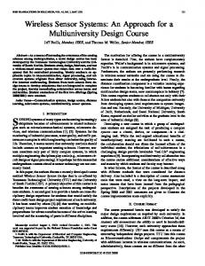
Simulations
The MIMO system performance was simulated in order to show its performance in the Gaussian channel. The QPSK signals were transmitted over four transmit antennas. Four receive antennas received the transmitted signals. Fig. 3 shows the results obtained by simulations. The maximum likelihood detection gives the best results. The degradation of about 3dB is observed when V-BLAST minimum mean square estimation algorithm is used instead. We found out that the MMSE V-BLAST algorithm is very sensitive to the estimated signal to noise ratio. The misestimation of the signal to noise ratio in MMSE V-BLAST [11] leads to a significant degradation of the system performance. When the zero forcing algorithm is used instead of MMSE, an additional increase in the transmitted power by 7dB is required to retain the same BER. The system performance is the worst when the pseudoinverse of the channel matrix is used to detect the transmitted data.
Figure 3. Simulation results
8
Conclusion
The current work in space-time coding is oriented towards the design of space-time trellis codes, multichannel equalisation and their application to WCDMA. Optimal receivers are difficult to implement, therefore fast suboptimal algorithms suitable for high speed networks are searched for. Most of the equalisation and estimation algorithms assume that receivers have perfect symbol timing synchronisation. However, training sequences from the receive antennas lose their orthogonality because of different delays in individual paths. Thus, the imperfect carrier and timing synchronisation lead to significant performance degradation. Optimal symbol timing synchronisation for the MIMO systems remains an unsolved problem. The capacity of the MIMO systems
in frequency selective channel with correlated multipath fading has also to be solved too. We believe that by implementing an appropriate model, including mutual correlation dependencies among paths in frequency selective MIMO subchannels, answers will be given to most of the open issues.
9
References [1] W. C. Y. Lee, Mobile Cellular Telecommunications Systems, Mc Graw-Hill 1995. [2] G. J. Foschiny, M. J. Gans, “On Limits of Wireless Communications in Fading Enviroment when Using Multiple Antennas”, Wireless Personal Communications Vol. 6, No. 3, 311-335, 1998. [3] E. Telatar, “Capacity of Multi-antenna Gaussian Channels”, Rm. 2C-174, Lucent Technologies, Bell Laboratories, USA 07974. [4] V. Tarokh, N. Seshari, R. Calderbank, ”Space-Time Codes for High Data Rate Wireless Communication: Performance Criterion and Code Construction”, IEEE Trans. on Inf. Theory, vol . 44, no. 2, March 1998. [5] S. Alamounti, “A simple transmitter diversity technique for wireless communications”, IEEE Journal on Sel. Area Of Comm., Special Issue, Vol. 16, no. 8, 1998. [6] V. Tarokh, H. Jafarkhani, A. R. Calderbank, “Space-time Block Codes from Orthogonal Designs”, IEEE Trans. on Inf. Theory, Vol. 45, July 1999. [7] J. Balakrishnam, M. Rupp, H. Viswanathan, “Optimal Channel Training for Multiple Antenna Systems”, Proc. Of Conf. On Multi-acces, Mobility and Teletraffic, Duck Key, FL, USA, December 2000. [8] Ch. Komninakis, Ch. Fragouli, A. H. Sayed, R. D. Wesel, ”Multi-Input Multi-Output Fading Channel Tracking and Equalization Using Kalman Estimation”, IEEE Transactions on Signal Processing, Vol. 50, No. 5, p. 1065-1076, May 2002.
[9] A. Bjerke, J. G. Proakis, “Equalization and Decoding for Multiple-Input Multiple-Output Wireless Channels“, EURASIP JASP, Vol. 2002, No. 3, March 2002. [10] G. J. Foschini, “Layered Space-Time Architecture for Wireless Communication in Fading Environment When Using Multi-Element Antennas”, Bell Labs Technical Journal, Autumn 1996. [11] P. W. Wolninsky, G. J. Foschini, G. D. Golden, R. A. Valenzuela, “V-BLAST: An Architecture for Realizng Very High Data Rates Over the Rich-Scattering Wireless Channel”, Bell Labs Report.
Jan Vcelak received B.Sc. in electrical engineering from Czech Technical University (CTU) of Prague. Currently he is Ph.D. student at CTU, the Faculty of Electrical Engineering. Tomaˇz Javornik received his B.Sc., M.Sc., and Ph.D. degrees in electrical engineering from University of Ljubljana, Slovenia, in 1987, 1990 and 1993, respectively. He currently works as a researcher in the Department of Digital Communications and Networks at the Jozef Stefan Institute (JSI). Jan Sykora received his B.Sc. and Ph.D. degrees in electrical engineering from CTU, in 1987 and 1993, respectively. Since 2002 he is associate professor, CTU the Faculty of Electrical Engineering. Gorazd Kandus received B.Sc., M.Sc. and Ph.D. degrees in electrical engineering from University of Ljubljana, Slovenia, in 1971, 1974 and 1991, respectively. He is currently the Head of the Department of Digital Communications and Networks at the JSI and Associate Professor at the Faculty of Electrical Engineering, Computer Science and Information Technology, University of Maribor. Sreˇco Plevel received B.Sc. degree in 2002 at the Faculty of Computer and Information Science, University of Ljubljana. Since 2002 he is employed at the JSI as Junior Researcher.