governing physics in the micro domain such as Van der. Waals forces, electrostatic .... resolution position encoder and a precision gearhead providing 0.1um ...
Seventh International Conference on Control, Automation, Robotics And Vision (ICARCV’02), Dec 2002, Singapore
Multiple Magnification Images Based Micropositioning for 3D Micro Assembly Seok Joo Lee*, Kyunghwan Kim**, Deok-Ho Kim***, Jong-Oh Park***, and Gwi Tae Park* * Department of Electrical Engineering, Korea University 1, 5-Ka, ANAM, SUNGBUK, SEOUL, KOREA ** Wooshin Mechatronics Co., Ltd. 772-2, Daerim-Dong, Yeoungdeoungpo, Seoul 150-070, Korea *** Microsystem Research Center, Korea Institute of Science and Technology P.O.BOX 131, CHEONGRYANG, SEOUL, 130-650, KOREA
Abstract This paper presents micropositioning system using feedback of multiple magnification images from CCD cameras mounted on an optical microscope. In order to guarantee of the accurate micropositioning to micro assembly system, high precise sensors are required. But many kinds of sensors, which are used in macro world, have insufficient resolution and size. The visual data from an optical microscope have vast information, however, the single field-of-view of optical microscope essentially limits the workspace of the micromanipulator and the low depth-of-field makes it difficult to handle micro parts. To overcome these problems and increase and precision of micropositioning system, we use multiple magnification images that have same viewpoint. The use of multiple magnification images reduces the time consuming for handling of micro parts and increases precision of micropositioning. We propose this method for micropositioning system.
1
Introduction
In the past two decades have been developed diverse micro electromechanical devices. The processing techniques for these devices are also equally diverse, and in some cases these methods are not compatible. The needs of high levels of precision and repeatability are required despite the fact that the mechanics of the micro domain have proven to be difficult to model accurately. It is due to the fact that mechanics in the micro domain are substantially different from the macro domain where most manipulation research has been conducted. The governing physics in the micro domain such as Van der Waals forces, electrostatic forces, and surface tension are only approximately known. Therefore accurate estimation and modeling is not possible over entire micro domain. As a result, open loop positioning techniques are not sufficient for the micro domain. A sensor-based micropositioning system is developed in order to guarantee both high precision and repeatability. Visual data from a CCD camera mounted on an optical microscope have very useful information for micromanipulation. They also have many applicable image processing algorithms that have been developed and
914
verified their performance in the past. As a matter of fact, in micro domain most systems use CCD camera mounted on an optical microscope because of the inadequacy of sensors which have suitable size and high-resolution [1][4][6]. However, there exist remarkable differences between highly magnified visual data and general macro visual data. These differences offer both merits and demerits to performance of image processing in the micro domain. Highly magnification images under on optical microscope offer plenty of information for handing micro parts. For instance, surfaces that appear smooth at normal magnification were highly textured under a magnification lens system. Smooth boundaries also appear rugged under a magnification lens. Moreover focused and defocused image data offer meaningful information for calculating difference of heights of numbers of objects, etc. Such elaborate and plenty information makes a vision sensor suitable for the micro domain. But sometimes some of data under an optical microscope offer redundant information and that causes difficulty in image processing such as feature extraction, and boundary extraction, etc. It is natural that the images, which have bigger scale of enlargement, have more precise information. In the same way, using visual data for micromanipulation, the bigger enlargement ratio is more useful for getting precise information about target object. But higher magnification images bring narrower field-of-view and consequently it limits field for object recognition and possible work area. Also slight movement of micro positioner brings large displacement in highly magnified image. So small amount of displacement error causes disappearance of target object in sight. Many researches have been made to solve the problems mentioned above. Those researches have used object lens at microscope or multiple cameras that have different magnification and different viewpoint. The use of multiple object lenses causes large time consuming and difficulty of manipulation. Moreover, new focusing operation is needed at each time of at exchanging the lenses. And in the use of multiple cameras, the complex image calibration process is needed. So it adds calculation load to vision system and also increases calculation time. Accordingly the reliance of result cannot be guaranteed. In this paper we present micro vision system for
dexterous micro assembly, which have ability of getting multiple images simultaneously, and they have same viewpoint but have multiple enlargement ratio. After describing vision system, we propose effective image processing algorithms and micropositioning strategy for using above multiple enlargement visual data. The use of those multiple images makes it possible to overcome the limitation of field-of-view and increase efficiency of micropositioning and its precision. Also reliable visual data can be obtained through the accomplishment of simple image calibration, and it is effective in the recognizing and tracking of multiple object and in the autofocusing for micropositioning. It reduces operation time for micropositioning and increases precision and repeatability of micropositioning system.
2
Micropositioning System
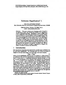
Micro position system is composed of three parts. An optical stereomicroscope and three CCD cameras mounted on stereomicroscope is the first part. The second part is micro XYZ stage. And the last part is a high performance PC that has controller for micro XYZ stage and an image processing board. Fig. 1 below shows the system architecture of micropositioning system.
MZ-12.5 optical microscope is 97mm while general optical microscope has small working distance around 10mm, which restricts the workspace of micromanipulator. The micropositioning XY-stage(M-126.DG of PI co.) is leadscrew-driven translation stage with the travel range of 25mm. Precision crossed roller bearings guarantee straightness of travel of better than 2 µm . It uses a compact closed loop DC motor with shaft-mounted high resolution position encoder and a precision gearhead providing 0.1um minimum incremental motion and designed resolution is 0.0085µm . The micropositioning vertical stage (M-501.1DG of PI co.) uses precisionground re-circulating ballscrew with preloaded nuts, which provide low-friction and backlash-free positioning. It has 12.5mm travel range and designed resolution is 0.005µm . Fig.2 shows software architecture for vision-based micropositioning system. The multi-thread method is used for real time data translation. GUI(Graphic User Interface), image processing and micropositioning stage control threads share their information. OS : WINDOWS 2000 / COMPILER : VISUAL C++ 6.0 MUTIPLE THREAD BASED / DIALOG BASED GUI
slpjhGvG t vGzGT
jjkG j
oU G
GUI THREAD
IMAGE PROCESS THREAD
}U G
}pzpvuGGpup{phspl
pthnlGnyhiGVG}pl~
yniGihukGkp}pzpvu
{hnl{GtvklsGpthnl zlslj{GhukGzh}l
}pzpvuGkh{hG jvu{yvs
pthnlGwyvjlzzpunG kh{hGihzl
{oylhkGjvu{yvs
tvklsGkh{hGihzl
zov~Gviqlj{G {yhqlj{vy
wh{{lyuGth{jopun
jjkG j
jjkG j }GzGJX }GzGJY
MICRO POSITIONER CONTROL THREAD jhsj|sh{l zjhslGmhj{vy {yhuzyh{lGwplsG kh{hG{vGw|szlGkh{h wpkGjvu{yvssly nlulyh{lGz{hnlG tv}punGGjvtthuk
}GzGJZ tGG z
jGwj tGTG kzwGpG kzwG nGG wGi i
Fig. 2. Software Architecture
|GpGJYU oTtGp
3 Micro Vision System
}nhGj }nhGj |G tG}GpG |GpGJXU pGJXU tG}GpGGk Gk
j_[YGG tGzG tG j j
In this section, we define multiple image space and explain autofocusing and recognition algorithms by using multiple magnification images.
Fig. 1. Composition of Micropositioning System The system has optical stereomicroscope (MZ-12.5 of Leica co.) with superior recognition ability for 3D-shaped micro parts, multiple CCD cameras (XC-55 of Sony co.), and a DSP frame grabber (GENESIS of Matrox co.). Obtained visual data from three CCD cameras are fed into the image processing board, and three CCD cameras are synchronized both horizontally and vertically. The optical stereomicroscope has wide range of magnification, high resolution, and long working distance. Also its fieldof-view is larger by 8 times at low magnification and 10 times at high magnification than general optical microscope (Mitutoyo FS60 optical microscope was referred), and it could recognize from a few micrometers to several millimeters. Moreover the working distance of
915
3.1 Multiple Image Space Definition The main characteristic of micro vision system is the system simultaneously offers multiple magnification images that have same viewpoint. They have same cartesian 2D coordination, which are shown Fig.3. y
I 1 ( x0 , y0 )
I1 ( x , y )
y
I 2 ( x0 , y0 )
I2 ( x , y )
y
I 3 ( x0 , y0 )
I3 ( x , y )
Fig. 3. Basic Definition of Image Coordination We define these three image space to I1 ( x , y ) , I 2 ( x , y )
and I 3 ( x , y ) . Each x and y denotes that number of pixels in x-axis and number of lines in an image. Also all of them have same resolution of 640 × 480 × 8bits , and they have different enlargement ratios as I1: I 2 : I 3 = 1.0:1.5:3.0 . y
y
x I '1 ( x0 , y0 )
I ' 2 ( x, y)
I '1 ( x , y )
x
x
I ' 3 ( x0 , y0 )
I ' 3 ( x, y)
x
∑∑
y
x
y
/
Fig. 4. New Definition of Image Coordination As shown in Fig. 4, we redefine the image coordination of Fig. 3 for easy calculation of relationship of multiple input images. After redefining image coordination, we get Eqs (1) and (2). (1) I '1 ( x , y) = I ' 2 (15 . x, 15 . y) (2) I '1 ( x , y) = I ' 3 (3x,3 y) ( where, - 320 < 15 . x < 320 and - 240 < 15 . y < 240
- 320 < 3x < 320 and - 240 < 3 y < 240)
∑∑
Let FX and FY , respectively be filtering results applied to an image along the horizontal and vertical direction. The result of F (m) is focus value at the vertical stage position m. For the fast finding of the best focusing position in the focus range by adjusting the micro stage, we use hill climbing search algorithm [5].
y
I ' 2 ( x0 , y0 )
pass filter, the calculation of focus value can be proceeded by using Eqs (3). (3) F ( m) = FX2 + FY2
/
Input visual data I1 , I 2 and I 3 have close relationship and I 2 , I 3 have more detail information than I 1 . Therefore, visual data I 2 and I 3 will be used for accurate micropositioning while visual data I 1 will be used for the operations which require the large filed-ofview. This selective view offers effective information and incensement of precision to micropositioning system. / /
3.2 Autofocusing In order to visually servo the micromanipulator in executing its task of handling and assembling microstructures under the microscope, an accurate, and automated autofocus system is required [2]. Most of passive autofocus techniques for microscopy have been developed for the biology and medicine areas. In these applications there is only one focal plane, and the samples to be observed are always planar. However, there are two or even more different focal planes in the fieldof-view of microscope: the mounting base onto which parts are placed, the parts themselves, and the gripping device. So, dynamic autofocusing system is needed for obtaining accurate focused image, which focused on concerned focal plane. For this reason we have divided our approach to autofocus into coarse and fine tuning by using multiple magnification images. Coarse tuning is performed in the I 1 region. After defining concerned focal plane at I 1 image, autofocusing is executed. And then we recalculate principal focusing position at the high magnification image of I 3 . The coarse tuning is executed for the fast finding of near position of focused image and also for the determination of the focal plane. And the fine tuning is for the finding of exactly focused position. We use micro vertical stage that has the possible displacement of 1cm. The uses of linear-phase FIR high-
916
3.3 Recognition Algorithm Characteristic points matching and pattern matching methods are widely used for object recognizing algorithm. However, characteristic point matching method needs preprocessing step for characteristic point detection. This preprocessing may cause time delay for computation, so it is improper for real time control. On the other hand, pattern matching method is just the comparison of target image and model image, so pattern matching algorithm becomes fit for object recognizing by the assistance of developed hardware such as high performance DSP, in recent years. Generally, pattern matching is performed by the equation of correlation in the convolution type as below; N
r = ∑ Ii Mi
(4)
i =1
where, r , I i , M i are the correlation value, the pixel value of target image and the pixel value of model image. The correlation operation can be seen as the form of convolution where the pattern-matching model is analogous to the convolution kernel. In fact, ordinary (unnormalized) correlation is exactly the same as the convolution. In this case, the area that has maximum correlation value is the most similar area of model image; so we can find the pattern by calculating the coordinates. Unfortunately, with ordinary correlation, the correlation value r increases if the image gets brighter. In fact, the function reaches a maximum when the image is uniformly white, even though at this point it no longer looks like the model. The solution is to use a more complex, normalized version of the correlation function ; r=
N ∑ IM − ( ∑ I ) ∑ M
(5)
[ N ∑ I − ( ∑ I ) 2 ][ N ∑ M 2 − ( ∑ M ) 2 ] 2
With this expression, the result is unaffected by linear changes (constant gain and offset) in the image or model pixel values. The result reaches its maximum value of 1 the image matches the model exactly, gives 0 where the model and image are uncorrelated, and is negative where the similarity is less than might be expected by chance. To reduce the calculation time, reliable method of reducing the number of computations is to perform a socalled hierarchical search. Basically, a series of smaller, lower-resolution versions of both the target and the model image are produced, and search begins on a more reduced scale[7]. The search starts at low resolution to find likely-
match candidates quickly. The search process iterates on the higher resolutions than that of the formal one sequentially to refine the positional accuracy and make sure that the matches found at low resolution actually are occurrences of the model. Because the position is already known from the previous level, the correlation function is evaluated only at the very small number of locations. But, if the level were too high, original image would be damaged. So the search algorithm must trade off the reduction in search time against the increased chance of not finding the pattern at very low resolution. Above pattern matching algorithm is not suitable for object handling. For handling micro objects by micro gripper, additional image processing algorithm for extract gripping points is needed. We use this pattern matching algorithm only for object positioning.
large field of view for observing the workspace. We use both data for effective micropositioning and for precise micropositioning. Fig. 6 shows the strategy of micropositioning for moving vertical stage. After concerned region is selected at lowly magnified image space, autofocusing algorithm is executed. After finding the exactly focused position, same operation is executed at the highly magnified image space for finding more precisely focused position.
kGG GOXWWGP
//
4
OYP
OXP
Micropositioning
mGG GOXWWGP
O[P
OZP
l GGG GOZWWGP
uGGGG GOZWWGP
4.1 Control Loop In the micro domain, accurate estimation and modeling are not possible due to the different mechanics of macro domain. Therefore, accurate estimation and modeling are not possible over entire micro domain. As a result, open loop positioning techniques are not sufficient for the micro domain. Vision is non-contact sensing modality that provides dense information about the environment and enables recognition of objects. However, because of this intensive information, fast closed loop systems could not be realized until recently with the advent of sufficiently powerful microprocessors. With the advancement in microprocessor’s speed, it becomes possible to incorporate a vision sensor into the closed loop system. Fig. 5 shows closed control loop of micropositioning system./ ref. Image Processing (pattern matching)
Extract Position Data of Micro Parts
-
+
measured position
image data
position vector for micro positioner Visual Servo Control
position error
Fig. 6. Micropositioning strategy for autofocusing Fig. 7 shows micropositioning strategy for moving XYstage. First, system searches the object using lowly magnified image space. It is easier to find than using highly magnified image space. If it succeeds in finding object image processing algorithm calculate its current position and target position, and generate moving trajectory. And move the micro XY-stage using visual feedback data of I 1 . After finishing the operation, the system examines the position of object by using more highly magnified image space I 2 , I 3 . If there exist position errors at the highly magnified image space, the system resumes micropositioning by using highly magnified visual feedback data. This strategy is efficient for high precision of micropositioning.
Camera Mounted On Microscope
Autofocusing
object pose
Fig. 5. Closed control loop for micropositioning
Pattern Matching in the lowest magnification Image space
Position feedback is obtained in the form of visual data from a CCD camera on an optical microscope that is incorporated into closed loop control architecture.
Moving micro XY Stage using visual feedback information Pattern Matching in the higher magnification image space
4.2 Micropositioning Strategy
Moving micro XY Stage using visual feedback information
For micromanipulation, two kinds of micropositioning are needed. One is micropositioning of vertical micro stage for autofocusing, and the other is XY-micro stage positioning for handling of micro objects. Highly magnified image is effective for obtaining precise data about micro objects. But lowly magnified image offers
917
Fig. 7. Micropositioning strategy
5
Experiments and Results
5.1 User Interface The user interface is divided into two parts. The first one shows multiple enlargements images and offers information of recognized micro objects to user. The Fig. 8 shows user interface part 1. The lower part on the right side window is for moving micro XY-stage by shifting and clicking the mouse point to the target area. zGaGG_W
zGaGGXYW
different magnification image. So we search and center the micro object roughly by using I1 image space data. After finished centering operation in I1 image space, the second and the third centering is executed for more precise micropositioning. Fig. 8 shows the example of micropositioning. The initial position of needle type micro object is (162, 118) in I1 image space. And target position is (320, 240). And each magnification of I1 , I 2 / and/ I 3 / are 100, 150 and 300.
zGaGGY[W
OX]YSXX_P
OZYWSY[WP
OZYWSY[WP
OZX_SYZ`P
OZX]SYZ]P
OZYWSY[WP
Fig. 8. User interface 1. Fig.9 shows the second user interface. It has camera control module, image processing control module, and stage control module and also have three sub-windows for showing trajectory of recognized objects.
Fig. 10. Centering of micro object
5.3 Autofocusing Fig. 11 shows the result of calculated focus value using autofocusing algorithm that is described in section 3.2. The graph shows that the focus value is larger when the vertical stage is closer to exactly focused position and graph shows symmetrical figure. The 496th position of vertical stage offers exactly focused image. In this experiment, the stage moves 1000 times per 10um to upper direction. And the image has magnifying power of 100.
OP x 10
Fig. 9. User interface 2.
OP
OP
O P
OP
18
4.5
(c) 4
5.2 Micro Parts Centering Fig. 10 shows the experiment of object centering. Object centering is positively needs for micromanipulation. If the object is out of sight in image region, micro-manipulation is impossible, therefore centered position of a micro object is most effective for micromanipulation. Object recognition is accomplished in whole operation and position information is obtained in real time. For micro object handling, higher magnification image is more effective and has more precise information, but it limits field-of-view. So we use both lowly and highly magnified visual information in micropositioning system. Also the position error exists in
918
3.5 3
2.5 2
(b)
1.5
(d)
1
(a)
0.5
(e)
0 0
100
200
300
400
500
600
700
800
Fig. 11. Focus value of micro image
900
1000
x 10
14
17
For handlings of micro objects, there are many remaining problems to be solved. More precise object recognition algorithm is needed. Development of image processing algorithm for micro image processing is one of serious problem. The different height and overlapping of micro object and micro gripper is have an influence on vision based micropositioning system and micromanipulation. For solving these problems we are doing research about developing image-processing algorithms suitable for micromanipulation.
G G G a G [ _ \
12
G a G Z W W G
10
8
6
G G G a G [ ^ ]
G a G X W W G 4
2
0 0
100
200
300
400
500
600
700
800
900
1000
(a ) F o c u s v a lu e a b o u t w h o le im a g e r e g io n 9
x 10
Acknowledgement
17
G G G a G [ ^ \ 8
The authors wish to acknowledge that this paper is a result of the research accomplished with the financial support of the Microsystem Research Center, Seoul, Korea, which is carrying out one of the 21st Century’s New Frontier R&D Projects sponsored by the Korea Ministry of Science & Technology
G a G Z W W G
7 6 5 4
G G G a G [ _ Y
3
G a G X W W G
2
References
1 0
0
100
200
300
400
500
600
700
800
900
1000
(b ) F o c u s v a lu e a b o u t o b je c t r e g io n
Fig. 12. Experiment result of autofocusing Fig. 12 shows the result of autofocusing. It shows that the different scale of image for the same image, and offers different exact focusing value. So, for more precise focusing, using highly magnified image is needed. And also the graph shows that using object region is more effective for precise focusing. The difference of exact focus value between (a) and (b) is because the background image impacts on the focus value. The exactly focused position is different between image space I 1 and I 2 . The exactly focused image is basis for obtaining precise visual data; that is to say, defocused image itself contains the image processing errors.
6
Conclusions
In this paper we illustrate multiple magnification images based micropositioning system and its architecture. The micro images have different characteristics when they are compared with macro images. The micro image offers more precise information about micro object. That vast visual information provides possibility of vision based micropositioning, but certain information is redundant for object recognition in micropositioning system. Also high enlargement ratio of optical microscope limits field of view. We solve these problems using multiple magnification based micro vision system. Micropositioning operation for micro assembly is divided into two parts. One is micropositioning of vertical micro stage for autofocusing and the other is for X and Y micro stage. For using multiple magnification images effectively, we established the micropositioning strategy and the strategy worked excellently, and as a result, increases precision of micropositioning.
919
[1] Seiji Hata, Ko" ichi Sugimoto, and Ichiro Ishimaru (Kagawa Univ., Japan) “3-D Vision Systems and Its Computer Model for Micro-Operation”, International Symposium on Robotics, pp. 686-691, April 2001 [2] Ng Kuang Chern, N.; Poo Aun Neow; Ang, M.H., Jr., "Practical issues in pixel-based autofocusing for machine vision", Robotics and Automation, 2001. Proceedings 2001 ICRA. IEEE International Conference on, Volume: 3, 2001, Page(s): 2791 -2796 vol.3 [3] Sano, T., Yamamoto, H. “Study of Micromanipulation Using Stereoscopic Microscope”, Instrumentation and Measurement Technology Conference, 2000. IMTC 2000. Proceedings of the 17th IEEE, Volume: 3 , 2000 Page(s): 1227 -1231 vol.3 [4] Bharath Mukundakrishnan, "Design for Visually Sevoed Microassembly" Technical Report, Advanced Microsystems Laboratory Department of Mechanical Engineering University of Minnesota, February 2000 [5] Kang-Sun Choi; Jun-Suk Lee; Sung-Jae Ko, "New autofocusing technique using the frequency selective weighted median filter for video cameras", Consumer Electronics, IEEE Transactions on, Volume: 45 Issue: 3, Aug. 1999, Page(s): 820 –827 [6] Barmeshwar Vikramaditya "Micropositioing Using Active Vision Thechniques", Submitted as partial fulfillment of the requirements for the degree of Master of Science in Mechanical Engineering in the Graduate College of the University of Illinois at Chicago, 1997 [7] Matrox Image Library Users Guide, Matrox Electronic System Ltd., 1997.