Laporan ini membincangkan proses pemesinan aloi titanium menggunakan
proses pemesinan ... Kerja pemesinan aloi titanium dilakukan menggunakan
mesin.
MULTIPLE OBJECTIVE OPTIMIZATION OF ELECTRICAL DISCHARGE MACHINING ON TITANIUM ALLOY USING GREY RELATIONAL ANALYSIS
MUHAMMAD ALIFF NAZREEN BIN NORAZMI
Thesis submitted in partial fulfilment of the requirements for the award of the degree of Bachelor of Mechanical Engineering with Manufacturing Engineering
Faculty of Mechanical Engineering UNIVERSITI MALAYSIA PAHANG
JUNE
2012
vi
ABSTRACT
This report deals with the machining workpiece Titanium Alloy using electrical discharge machining (EDM). The objective of this thesis is to optimize the surface roughness (SR), electrode wear ratio (EWR) and material removal rate (MRR) by using grey relational analysis (GRA) with orthogonal array (OA) and to discuss on the significant result by using Analysis of Variance (ANOVA). The machining of Titanium Alloy workpiece was performed using the EDM machine AQ55L (ATC) and the analysis done using equation for GRA and STATISTICA software for ANOVA. In this study, the machining parameters, namely workpiece polarity, pulse off time, pulse on time, peak current and servo voltage are optimized. A grey relational grade obtained from the grey relational analysis is used to solve the EDM process with the multiple performance characteristics. Optimal machining parameters can then be determined by the grey relational grade as the performance index. Based from the result, the most significant parameter that affects the MRR, EWR and SR was the peak current while significant parameter was pulse off time. Experimental results have shown that machining performance in the EDM process can be improved effectively through this approach.
vii
ABSTRAK Laporan ini membincangkan proses pemesinan aloi titanium menggunakan proses pemesinan nyahcas elektrik (EDM). Objektif tesis ini adalah untuk mengoptimumkan kekasaran permukaan (SR), nisbah kehausan elektrod (EWR), dan kadar penyingkiran (MRR) dengan menggunakan analisis hubungan kelabu (GRA) dengan susunan orthogonal (OA) dan membincangkan keputusan yang signifikan menggunakan analisis perbezaan (ANOVA). Kerja pemesinan aloi titanium dilakukan menggunakan mesin AQ55L (ATC) dan analisis menggunakan persamaan bagi GRA dan perisian STATISTICA untuk ANOVA. Dalam kajian ini, parameter memesin iaitu kekutuban keluli kerja, pulse off time, pulse on time, arus puncak dan servo voltan yang dioptimumkan. Gred hubungan kelabu didapati daripada analisis hubungan kelabu digunakan untuk menyelesaikan pelbagai proses ciri-ciri prestasi. Parameter memesin optimum boleh ditentukan dengan gred hubungan kelabu sebagai indeks prestasi. Daripada keputusan, parameter paling signifikan yang member kesan kepada MRR, EWR and SR adalah arus puncak manakala signifikan parameter adalah pulse off time. Keputusan eksperimen telah menunjukkan bahawa prestasi memesin boleh ditingkatkan dengan efektif melalui kaedah ini.
viii
TABLE OF CONTENTS Page SUPERVISOR’S DECLARATION
ii
STUDENT’S DECLARATION
iii
DEDICATION
iv
ACKNOWLEDGEMENTS
v
ABSTRACT
vi
ABSTRAK
vii
TABLE OF CONTENTS
viii
LIST OF TABLES
xi
LIST OF FIGURES
xii
LIST OF SYMBOLS
xiii
LIST OF ABBREVIATIONS
xiv
CHAPTER 1
CHAPTER 2
INTRODUCTION
1.1
Introduction
1
1.2
Importance of research
2
1.3
Objectives
2
1.4
Problem statement
2
1.5
Project scope
3
LITERATURE REVIEW 2.1
Introduction
4
2.2
Electrical Discharge Machine
4
2.3
Die-sinking EDM
5
2.3.1
Principle of Die-sinking EDM
6
2.3.2
EDM Spark
7
2.3.3
Dielectric Fluid
7
Material Removal Rate (MRR)
8
2.4
ix
2.5
Electrode Wear Ratio (EWR)
9
2.6
Surface Roughness (SR)
9
2.7
EDM process parameters
10
2.7.1
Servo Voltage
10
2.7.2
Peak Current
11
2.7.3
Pulse on and off duration
11
2.7.4
Workpiece Polarity
12
2.7.5
Dielectric Pressure
13
2.8
CHAPTER 3
14
METHODOLOGY
3.1
Introduction
14
3.2
Flow Chart
14
3.3
Experimental Setup
16
3.3.1
Electrode Material
16
3.3.2
Workpiece Material
16
3.3.3
Machine
17
3.4
CHAPTER 4
Grey Relational Analysis (GRA)
Design of experiment
18
3.4.1
18
Design factors selected
3.4.2 Experimental Design
19
3.5
Analysis of Variance
21
3.6
Confirmation Test
21
RESULTS AND DISCUSSION 4.1
Introduction
22
4.2
Orthogonal Array Experiment
22
4.3
Grey relational analysis for the experimental results
24
4.4
Analysis of Variance (ANOVA)
29
4.5 4.6
Confirmation Test Most Significant Factor- Peak Current
31 32
4.7 Significant Factor-Pulse-off Time
36
x
CHAPTER 5
CONCLUSION AND RECOMMENDATIONS
5.1
Introduction
38
5.2
Conclusions
38
5.3
Recommendations
39 40
REFERENCES APPENDICES A
Gantt Chart
43
B
Grey Relational Analysis Experimental and Calculation
44
xi
List of tables
Table No.
Title
Page
2.1
General polarity guidelines
12
3.1
Copper Tungsten properties
16
3.2
Titanium properties
17
3.3
Machining parameters and their respective levels
4.1
Parameter and its level
24
4.2
Results of MRR, EWR and SR in L18 OA
25
4.3
Normalized results
26
4.4
GRCs and GRGs
28
4.5
Response table for the grey relational grade
29
4.6
Results of the Analysis of Variance
31
4.7
Result of the confirmation experiment A2B2C1D2E1F3
33
19
xii
List of Figures
Figure No.
Title
Page
2.1
Schematic diagram of basic EDM System
5
3.1
Flow chart outlining the steps undertaken
15
3.2
AQ55L (ATC) Die-sinking EDM
17
4.1
Grey relational grade plot
30
4.2
Percentage contribution vs Parameters
32
4.3
MRR plot
34
4.4
EWR plot
35
4.5
SR plot
36
xiii
List of Symbols ti
Pulse On-time
to
Pulse Off-time
µs
The duration of time machining
µΩ
Electrical resistivity
s
second
Wb
Weight of workpiece material before machining (g)
Wa
Weight of workpiece material after machining (g)
A
Ampere
μm
Micrometer Normalized value Ideal value
Distinguishing coefficient Total mean of the Grey relational grade Mean of the Grey relational grade at optimal level
q
Number of the machining parameters
xiv
List of Abbreviations EDM
Electrical Discharge Machining
MRR
Material Removal Rate
EWR
Electrode Wear Ratio
V
Voltage
I
Current
SME
Society of Manufacturing Engineering
GRA
Grey Relational Analysis
OA
Orthogonal Array
DOE
Design of Experiment
EWW
Weight of Electrode Use
WRW
Weight of Workpiece Used
ANOVA
Analysis of Variance
GRG
Grey Relational Grade
GRC
Grey Relational Coefficient
MS
Mean Square
D.O.F
Degree of Freedom
SS
Sum of Square
F
Fisher Test
CHAPTER 1
INTRODUCTION
1.1 Introduction
Electrical discharge machining (EDM) is one of the most extensively used non-conventional material removal processes. Its unique feature of using thermal energy to machine electrically conductive parts regardless of hardness has been its distinctive advantage in the manufacture of mould, die, automotive, aerospace and surgical components. In addition, EDM does not make direct contact between the electrode and the workpiece eliminating mechanical stresses, chatter and vibration problems during machining.
The machine used in this study is a AQ55L (ATC) EDM and the workpiece material used is a Titanium Alloy. The important output parameters of the process are the material removal rate (MRR), electrode wear ratio (EWR) and surface roughness (SR). Grey Relational Analysis (GRA) is a method that used to get the desired information based on the relation with incomplete information. GRA require only a limited amount of data to estimate behavior of unknown systems. Lin (1998) presented the use of Grey relational grade to the machining parameters optimization of the electrical discharge machining (EDM) process. By using this method, we can determine and find the suitable parameter to optimize the electrical discharge machine on mild steel workpiece. This project is to investigate the optimum parameter required for MRR, EWR and SR by using GRA.
2
1.2 Importance of research
i.
Improve the quality surface finish of the cut metal.
ii.
Improve efficiency of production process.
iii.
Minimize the cost of production process.
iv.
Enhance the production rate.
1.3 Objective
i.
Optimize material removal rate (MRR), electrode wear ratio (EWR) and the surface roughness (SR), by using GRA with Orthogonal Array (OA).
ii.
Discuss on the significant result by using analysis of variance (ANOVA).
1.4 Problem statement
During the machining process, wear will occur on the electrode. This will affect the efficiency of the machining process and cost during the machining. Thus, to avoid wear and reduce cost, the optimum parameter on the MRR, EWR and SR must be obtain. The optimum parameter will optimize the usage of machine.
3
1.5 Project Scopes
This project will focus on machining parameter and the method used to optimize MRR, EWR and SR. The parameters that would be studied in this project are: i.
Peak current
ii.
Pulse off duration
iii.
Pulse on duration
iv.
Polarity
v.
Servo voltage
This project also focuses on the methods used which are GRA, OA and ANOVA in order to obtain the data. All of the methods used in this project were aimed to evaluate the best and optimum parameter stated above. SR, EWR and MRR could simultaneously satisfy requirements of both quality and as well as productivity with special emphasis on reduction of electrode wear that ensures increase in tool life. The optimal setting ensured minimization of SR and EWR, while maximizing MRR.
CHAPTER 2
LITERATURE REVIEW
2.1
Introduction
This section provides the basic fundamentals of the EDM process, parameters and methods involved in this project. A literature review is a body of text that aims to review the critical points of current knowledge and studies related to the project given.
2.2
Electrical discharge machine (EDM)
Electrical discharge machining (EDM) is one of the most extensively used nonconventional material removal processes. Its unique feature of using thermal energy to machine electrically conductive parts regardless of hardness has been its distinctive advantage in the manufacture of mould, die, automotive, aerospace and surgical components. In addition, EDM does not make direct contact between the electrode and the workpiece eliminating mechanical stresses, chatter and vibration problems during machining. Today, an electrode as small as 0.1 mm can be used to construct holes into curved surfaces at steep angles without drill „wander‟. (S. Kalpajian et al., 2003)
S. Webzell, (2001) states that, the foundation of EDM can be traced as far back as 1770, when the English chemist, Joseph Priestly, discovered the erosive effect of electrical discharges or sparks. Nevertheless, it was only in 1943 at the Moscow University where Lazarenko exploited the destructive properties of electrical discharges for constructive use. They developed a controlled process of machining difficult-tomachine metals by vaporizing material from the surface of metal. The Lazarenko EDM
5
system used resistance–capacitance type of power supply, which was commonly used at the EDM machine in the 1950s and later served as the model for successive development in EDM. (A.L. Livshits et al., 1960)
One of the conventional methods to avoid gap contamination is pressure flushing or suction flushing. Nevertheless, it is not always possible to make holes for flushing in electrodes, and even if possible, a uniform flow rate of the dielectric is difficult to obtain over a large working area. The periodical lifting of the electrode is another conventional method but too often lifting lowers the removal rate and the stagnation points at the bottom gap of the electrode cannot be avoided where arcing is apt to occur.
A self-flushing system which is based on a pumping effect by special movement of the electrode was proposed by Masuzawa et al., 1983. Kremer et a1., 1983 reported superior productivity of ultrasonic imposed EDM where ultrasonic vibration helps particles flow out of the gap smoothly.
2.3
Die-sinking EDM
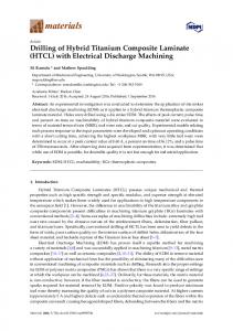
Figure 2.1: Schematic diagram of basic EDM System
6
Die-sinking EDM machines are also known as ram or vertical EDMs. The equipment used to perform the experiments was a die-sinking EDM machine of type AQ55L (ATC). Also, a jet flushing system in order to assure the adequate flushing of the EDM process debris from the gap zone was employed. The dielectric fluid used for the EDM machine was kerosene. Figure 2.1 shows the schematic diagram of a basic EDM system.
Die-sinking EDM, has four sub-systems, namely: i.
DC power supply to provide the electrical discharges, with controls for voltage, current, duration, duty cycle, frequency, and polarity.
ii.
Dielectric system to introduce fluid into the voltage area/discharge zone and flush away work and electrode debris, this fluid is usually a hydrocarbon or silicone based oil.
iii.
Consumable electrode.
iv.
Servo system to control in-feed of the electrode and provide gap maintenance
2.3.1 Principles of Die-sinking EDM
The workpiece is mounted on the table of the machine tool and the electrode is attached to the ram of the machine. A DC servo unit or hydraulic cylinder moves the ram and electrode in a vertical motion and maintains proper position of the electrode in relation to the workpiece. The positioning is controlled automatically and with extreme accuracy by the servo system and power supply. During normal operation the electrode never touches the workpiece, but is separated by a small spark gap. During operation, the ram moves the electrode toward the workpiece until the space between them is such that the voltage in the gap can ionize the dielectric fluid and allow an electrical discharge or spark to pass from the electrode to the workpiece.
7
2.3.2 EDM Spark
Kuneida et al., (2005) state, in EDM, the tool (anode) and the work piece (cathode) are immersed in a dielectric medium separated from each other by a small gap of the order of about 5-10 mm. A controlled spark is generated between the two electrodes by applying a voltage (200 V) which breaks down the dielectric medium causing the voltage falls to about 25-30 V (discharge voltage) and the current to rise to a constant value set by the operator. During the on- time of EDM spark (of the order of microseconds), electrons start flowing from cathode to anode which ionizes the dielectric medium and form a plasma channel between the cathode and anode. The intense heat generated in the plasma channel melts and even vaporizes some of the work and tool material causing material removal. DiBitonto DD, Eubank PT, (1989) shows the molten metal is held back at its place due to the large plasma pressure and as soon as the spark on-time is over (the spark collapse) the dielectric gushes back to fill the void. This sudden removal of pressure results in a violent ejection of the molten metal from the work surface forming small craters at locations, where the material has been removed. Controlled spark discharges between the tool and workpiece give the desired material removal and production of the cavities of desired shape on the work surface.
2.3.3 Dielectric Fluid
Kuneida et al. (2005) stated that for EDM, the dielectric serves to concentrate the discharge energy into a channel of very small cross-sectional area. It also cools the two electrodes, and flushes away the products of machining from the gap. The electrical resistance of the dielectric influences the discharge energy and the time of spark initiation. Dielectric fluid acts as an electrical insulator to help control the spark discharges. Thermal processing is required to be carried out in the absence of oxygen so that the process can be controlled and oxidation avoided.
8
Oxidation often leads to poor surface conductivity of the workpiece hindering further machining. Hence, dielectric fluid should provide an oxygen free machining environment. Moreover, during sparking it should be thermally resistant as well.
Ali Ozgedik et al. (2005) described that the use of kerosene as a dielectric liquid is very common in the published research. Distilled water, water solutions of sugar, glycol, glycerin and polyethylene glycol are also used as dielectric fluids. The use of kerosene gives a higher workpiece removal rate with increasing current compared with the other dielectrics. EWR increases with increasing current for kerosene while it decreases with the other dielectrics. Kerosene dielectric gives lower relative tool wear values compared with the other dielectrics for a low to medium range of current.
The functions of the dielectric fluid are to: i.
Act as an insulator between the tool and the workpiece.
ii.
Act as coolant.
iii.
Act as a flushing medium for the removal of the chips.
2.4
Material Removal Rate (MRR)
Maximum of MRR is an important indicator of the efficiency and cost effectiveness of the EDM process, however increasing MRR is not always desirable for all applications since this may sacrifice the surface integrity of the workpiece. A rough surface finish is the outcome of fast removal rates.
The material removal rate, MRR in EDM is calculated by the following formula:
(2.1)
Where: Wb = weight of workpiece material before machining (g) Wa = weight of workpiece material after machining (g) T = machining times (min)
9
2.5
Electrode Wear Ratio (EWR)
In EDM, the tool wear problem is very critical since the tool shape degeneration directly affects the final shape of the die cavity. The EDM operations, performed using tools designed and produced by considering the geometric tool wear characteristics, reduce the machining errors to a minimum level and result in parts of higher quality and lower cost.
(2.2)
Where: EWW = weight of electrode used (g) WRW = weight of workpiece used (g)
Although other ways of measuring MRR and EW do exist, in this work the material removal rate and electrode wear values have been calculated by the weight difference of the sample and electrode before and after undergoing the EDM process.
2.6
Surface Roughness (SR)
The EDM surface is formed by a series of discrete discharges between the electrode and workpiece, and consequently, an inspection of the machined surface reveals the presence of many craters. This machining technique is applicable to a wide variety of conductive materials irrespective of their mechanical properties, e.g. their hardness, strength, or toughness, etc. Furthermore, since no direct contact occurs between the electrode and the workpiece, the EDM process is suitable for the machining of brittle materials such as ceramic, and for those materials which are not readily machined using traditional machining methods.
10
According to an investigation performed by L.C. Lim (1991), small erosion area (SEA) machining (0.09–0.80 cm2) is one of the most problematic forms of EDM since the integrity of the EDM surface is degraded by the unstable arcing which always occurs during the machining process. The quality of an EDM product is evaluated in terms of its surface integrity, which is characterized by the surface roughness, and by the presence of a white layer, surface cracks, and residual stress. The roughness of the EDM surface is associated with the distribution of the craters formed by the electric sparks. Lim et al., (1991) has reported that only 15% of the molten workpiece material is flushed away by the dielectric. The remaining material re-solidifies on the EDM surface due to the fast cooling rate generated by the dielectric. This recast layer is referred to as the white layer since it is very difficult to etch and because its appearance when observed through an optical microscope is white.
2.7
EDM process parameters
Several parameters requirement should be considered in this EDM process such as servo voltage, peak current, pulse on-duration, pulse off-duration, workpiece polarity and dielectric pressure.
2.7.1 Servo Voltage
Servo voltage in EDM is related to the spark gap and breakdown strength of the dielectric. Before current can flow, the open gap voltage increases until it has created an ionization path through the dielectric. Once the current starts to flow, voltage drops and stabilizes at the working gap level. The preset voltage determines the width of the spark gap between the leading edge of the electrode and workpiece.
The range of voltage available in EDM equipment is between 40 to 400 DC. Higher voltage settings increase the gap, which improve the flushing conditions and help to stabilize the cut. MRR, electrode wear rate (EWR) and surface roughness increases, by increasing open circuit voltage, because electric field strength increases. (Kansal HK, Singh S, Kumar P et al., 2005)
11
2.7.2 Peak Current
The current increases until it reaches a preset level during each pulse on-time, which is known as peak current. Peak current is governed by surface area of cut. Higher peak current is applied during roughing operation and details with large surface area. This is the most important parameter because the machined cavity is a replica of tool electrode and excessive wear will hamper the accuracy of machining. New improved electrode materials like graphite, can work on high currents without much damage. (Ho KH, Newman ST et al., 2003)
2.7.3 Pulse On and Off Duration
In the study, Kansal HK, Singh S, Kumar P et al., (2005) state that, pulse duration is commonly referred to as pulse on-time and pulse interval is called pulse offtime. These are expressed in units of microseconds. Since all the work is done during pulse duration, hence this parameter and the number of cycles per second (frequency) are important. Material removal rate (MRR) depends upon the amount of energy applied during the pulse duration. Increased pulse duration also allows more heat to sink into the workpiece and spread, which means the recast layer will be larger and the heataffected zone will be deeper. Material removal rate tends to decrease after an optimal value of pulse duration.
Pulse interval mainly affects machining speed and stability of cut. Shorter interval results in faster machining operation. However, if the interval is too short, the ejected workpiece material will not be flushed away with the flow of the dielectric fluid and the dielectric fluid will not be deionized. This results in instability of the next spark. Erratic cycling due to unstable spark results in prolonged machining time. At the same time, pulse interval must be greater than the deionization time to prevent continued sparking at one point. Fuller JE (1996)
12
2.7.4 Workpiece Polarity The negative polarity of the tool − polarity gives a lower tool wear than that of + polarity in the range of low to medium discharge current values. At high current settings, the polarity has no significant effect on tool wear. A slight decrease relative wear is observed with increasing current in − polarity. In the case of + polarity, relative wear decreases significantly with increasing current. Relative wear does not vary significantly with current at high settings of current for both polarities. (Lee SH, Li XP et al., 2001)
It is very important to pay attention to the recommended polarity of various electrode-work piece combinations. The wrong polarity can have significant implications on speed, wear, and stability. It is best to consult the specific power supply technology documentation for polarity recommendations. General polarity guidelines are listed in Table 2.1.
Table 2.1: General polarity guidelines
Electrode Material
Polarity
Graphite on Steel: general purpose and Electrode Positive low wear Graphite on Steel: high speed and 20% Electrode Negative wear Graphite on Copper
Electrode Negative
Copper on Steel
Electrode Positive
Copper Tungsten on Steel
Electrode Positive
Copper Tungsten on Carbide
Electrode Negative
13
2.7.5 Dielectric Pressure.
Cogun C et al. (2002) write in their study that, the machining condition turns into an unstable regime when there is no flushing. This condition is called the “static dielectric condition” or “static condition”. Tool wear increases rapidly when the flushing pressure is increased beginning from the static condition. Increasing dielectric pressure at high-pressure settings does not result in a significant increase in tool wear. The increase in dielectric pressure at low-pressure settings results in a significant increase in relative wear, whereas the increase in pressure at high dielectric pressure settings insignificantly affects relative wear.
2.8
Grey Relational Analysis (GRA)
The Grey theory can provide a solution of a system in which the model is unsure or the information is incomplete. It also provides an efficient solution to the uncertainty, multi-input and discrete data problem. The relation between machining parameters and performance can be found out with the Grey relational analysis. (J.L. Deng et al., 1989)
CHAPTER 3
METHODOLOGY
3.1
Introduction This chapter will describe about the overall process of methodology in this
project, from the beginning until end of the project. There are four main processes that start with experimental, collecting the data, result analysis and confirmation test. All the processes will be described in this chapter by the flow chart. During this part, every information and data will be gathered together and concluded according to the objectives and scope of the project.
3.2
Flow Chart
Flow chart is an important step in order to make sure the project can be done on time. Based from the flow chart, the project started with the literature review of the project. Research was made through journals, websites, books and other related sources based on the title given. The flow chart for this project is shown as in Figure 3.1.
The design of experiment is conducted after all the information about the project is gathered. The required parameters need to be defined as a design factor. The experiment start after workpiece, electrode and machine setup was prepared. Then, collect the data of the experiment and analyse it based on the constructed table attached in the appendices.