... William S. Rabinovich, G. Charmaine Gilbreath, Rita Mahon, Mike S. Ferraro, Lee ...... John F. Kline, Joshua Resnick, H.C. Merk, and Michael J. Vilcheck, ...
NRL Release Number 06-1226-2171 Invited Paper
Multiple quantum well-based modulating retroreflectors for inter- and intra-spacecraft communication Peter G. Goetz, William S. Rabinovich, G. Charmaine Gilbreath, Rita Mahon, Mike S. Ferraro, Lee Swingen, Robert J. Walters, Scott R. Messenger, Linda M. Wasiczko, James Murphy, N. Glenn Creamer, Harris R. Burris, Mena F. Stell, Christopher I. Moore, Steven C. Binari, and D. S. Katzer Naval Research Laboratory, 4555 Overlook Ave. SW, Washington, DC, USA 20375 ABSTRACT Free space optics (FSO) can provide high data rates with efficient use of power. However, small platforms may not be able to support the payload requirements of a conventional FSO terminal. An alternative FSO terminal uses a modulating retro-reflector (MRR). MRRs shift most of the power, weight, and pointing requirements to one end of the link. With a MRR configuration, it is possible to establish a two-way FSO link using a single laser transmitter. The MRR terminal of these systems can be small, lightweight, and low power. The MRR maintains the small beam divergence of a conventional optical communications link, but gains the loose pointing advantage of an RF link, reducing the pointing requirements. Communication needs in space present many asymmetric scenarios in which a MRR architecture could be beneficial. This paper describes some of the current capabilities and limitations of MRR systems, as well as applications to space links. An evaluation of the radiation tolerance of modulators is presented. Keywords: Free-space optics, modulating retroreflector, multiple quantum well, radiation tolerance, FSO, MQW, MRR
1. INTRODUCTION Free space optical communication has emerged in recent years as an attractive alternative to conventional RF techniques. Free space optics (FSO) can provide high data rates with efficient use of power due to its high directionality. Narrow beamwidths provide exceptionally high antenna gains that are beneficial to size, weight, and power. They also decrease susceptibility to interference between platforms. However, narrow beamwidths also require highly accurate pointing and tracking. Size, weight, and/or power of a high-quality pointing and tracking system can exceed that of the communications hardware. If a platform is small or has little available power, the requirements of a conventional optical communications link may be prohibitive. An alternative to a conventional FSO terminal is a modulating retro-reflector (MRR). Using a MRR shifts most of the power, weight, and pointing requirements to one end of the link. This allows for asymmetric links between platforms with different capabilities. With a MRR configuration, it is possible to establish a two-way optical link using a single laser transmitter. Such systems can be lightweight and low power. Pointing requirements of the MRR are set by the field of view of the retro-reflector, generally about 10 to 20 degrees per retro-reflector. The retro-reflection is insensitive to platform jitter. Despite the very generous pointing tolerance, the retro-reflected beam has a divergence equal to the diffraction-limit of the retro-reflector (typically about 200 micro-radians). Thus the MRR end of the link maintains the small divergence of a conventional optical communications link, but gains the loose pointing advantage of an RF link. Communication needs in space present many asymmetric scenarios in which a MRR architecture could be beneficial. MRRs open up FSO communications to platforms previously unable to use it, such as nano-satellites. Space provides a nearly ideal environment for FSO from an optics point of view, eliminating the problems of scintillation and atmospheric absorption. As a result, terrestrial systems which are currently in use should have significantly improved ranges in space.
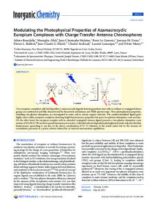
2. MULTIPLE QUANTUM WELL MODULATING RETRO-REFLECTORS (MRRS) A MRR couples a passive optical retroreflector such as a corner-cube or a cat’s eye retroreflector with an electro-optic modulator. Figure 1 shows an unmodulated (CW) laser interrogating a MRR comprised of an absorptive modulator and a retroreflector. If the interrogation beam is within the retro-reflector’s field of view, the beam will return to the interrogator with data impressed on it. Optical MRRs were demonstrated1 before the invention of the laser, but were
Photonics for Space Environments XI, edited by Edward W. Taylor, Proc. of SPIE Vol. 6308, 63080A, (2006) · 0277-786X/06/$15 · doi: 10.1117/12.694907
Proc. of SPIE Vol. 6308 63080A-1
Form Approved OMB No. 0704-0188
Report Documentation Page
Public reporting burden for the collection of information is estimated to average 1 hour per response, including the time for reviewing instructions, searching existing data sources, gathering and maintaining the data needed, and completing and reviewing the collection of information. Send comments regarding this burden estimate or any other aspect of this collection of information, including suggestions for reducing this burden, to Washington Headquarters Services, Directorate for Information Operations and Reports, 1215 Jefferson Davis Highway, Suite 1204, Arlington VA 22202-4302. Respondents should be aware that notwithstanding any other provision of law, no person shall be subject to a penalty for failing to comply with a collection of information if it does not display a currently valid OMB control number.
1. REPORT DATE
3. DATES COVERED 2. REPORT TYPE
JAN 2006
00-00-2006 to 00-00-2006
4. TITLE AND SUBTITLE
5a. CONTRACT NUMBER
Multiple quantum well-based modulating retroreflectors for inter- and intra-spacecraft communication
5b. GRANT NUMBER 5c. PROGRAM ELEMENT NUMBER
6. AUTHOR(S)
5d. PROJECT NUMBER 5e. TASK NUMBER 5f. WORK UNIT NUMBER
7. PERFORMING ORGANIZATION NAME(S) AND ADDRESS(ES)
Naval Research Laboratory,Code 7215, Remote Sensing Division,4555 Overlook Avenue, SW,Washington,DC,20375 9. SPONSORING/MONITORING AGENCY NAME(S) AND ADDRESS(ES)
8. PERFORMING ORGANIZATION REPORT NUMBER
10. SPONSOR/MONITOR’S ACRONYM(S) 11. SPONSOR/MONITOR’S REPORT NUMBER(S)
12. DISTRIBUTION/AVAILABILITY STATEMENT
Approved for public release; distribution unlimited 13. SUPPLEMENTARY NOTES 14. ABSTRACT
Free space optics (FSO) can provide high data rates with efficient use of power. However, small platforms may not be able to support the payload requirements of a conventional FSO terminal. An alternative FSO terminal uses a modulating retro-reflector (MRR). MRRs shift most of the power, weight, and pointing requirements to one end of the link. With a MRR configuration, it is possible to establish a two-way FSO link using a single laser transmitter. The MRR terminal of these systems can be small, lightweight, and low power. The MRR maintains the small beam divergence of a conventional optical communications link, but gains the loose pointing advantage of an RF link, reducing the pointing requirements. Communication needs in space present many asymmetric scenarios in which a MRR architecture could be beneficial. This paper describes some of the current capabilities and limitations of MRR systems, as well as applications to space links. An evaluation of the radiation tolerance of modulators is presented. 15. SUBJECT TERMS 16. SECURITY CLASSIFICATION OF: a. REPORT
b. ABSTRACT
c. THIS PAGE
unclassified
unclassified
unclassified
17. LIMITATION OF ABSTRACT
18. NUMBER OF PAGES
Same as Report (SAR)
11
19a. NAME OF RESPONSIBLE PERSON
Standard Form 298 (Rev. 8-98) Prescribed by ANSI Std Z39-18
restricted to short distances and low data rates. Recent advances in optoelectronic devices and FSO have greatly increased the capabilities of MRR systems. The Naval Research Laboratory has developed MRR systems using multiple quantum well modulators2 for a variety of space as well as terrestrial applications. This discussion deals specifically with multiple quantum well (MQW) modulators. Various other modulator technologies have been used in MRRs and compared elsewhere3.
Nanosat
Mothership
m ea b g m tin ea a b g l ro na er g t i In ds CW urne t Re
W or MQ ulat d mo
tro ctor e R fle re a er m Ca
Laser and telescope Figure 1: MRR system. Electrical signal is impressed onto the incident CW laser beam; data is returned to the interrogating satellite
2.1 Multiple Quantum Well Modulators Since 1998 the Naval Research Laboratory has investigated modulating retroreflectors based on semiconductor multiple quantum well (MQW) electro-optic modulators4. These types of modulators have very high intrinsic switching times, and in practice are limited in their modulation rate only by RC time constant, where R is the electrical resistance and C is the capacitance. Thus the maximum modulation rate is determined by the device capacitance, which is related to the device area, and the lateral resistance, which is determined by the area as well as the electrode design. The design of an MRR link must balance using a large optical aperture to return sufficient light with the degradation in the RC time that comes with large area devices. A MQW modulator is a PIN diode with multiple thin layers of alternating semiconductor alloys in the intrinsic region, as shown in Figure 2. These layers consist of a lower band-gap material, the well, and a higher bandgap material, the barrier. This type of modulator is attractive for modulating retroreflector applications because it can have a large area, and its modulation characteristics are essentially angular and polarization independent. Using InGaAs/AlGaAs MQW structures grown on GaAs substrates, operating wavelengths between 0.8-1.06 µm can be accessed5. Using InGaAs/InAlAs MQW structures grown on InP, the wavelength region around 1.55 µm can be accessed. The modulator is used in a surface-normal orientation to cover the aperture or focal area of the retroreflector. The distance the light travels through the active region is the thickness of the epitaxial layers, which is a few microns. A tradeoff between contrast ratio, optical transmission, tolerable capacitance, and available electronic drivers determines the number of quantum wells, and thus the thickness. Because the semiconductor layers are very thin, the conduction and valence bands are quantized, and the exciton absorption feature at the band-edge becomes narrower in linewidth and enhanced in absorption. The center wavelength of the exciton is determined by the composition of the well material as well as the width of the well. When a reverse bias is applied across the MQW, the electric field changes the quantum well potential, shifting the exciton feature to the red and changing the magnitude of the absorption at any given wavelength. A modulating voltage on the quantum well is then converted into an optical amplitude modulation over about a 10 nm bandwidth, as shown in Figure 3.
Proc. of SPIE Vol. 6308 63080A-2
0 Volts
Light in
0.3
p Contact
20 Volts
-1 MOW(1)
0.2 0.1
0.0
0.96 0.98 1.00 1.02 1.04 1.06 Wavelength (gm)
Figure 3 - Absorption spectra of large area MQW modulator for both 0 V and 20 V applied reverse bias
Figure 2: The layer structure of a MQW modulator
3. MRR LINKS The link equation for MRR systems can be written as an extension of the conventional FSO equation. In addition to the transmitter and receiver terms, additional terms are included to account for the MRR’s antenna gain, optical loss, and modulation efficiency. Because the light completes a round trip, atmospheric attenuation and free space range loss both appear twice. This free space range loss is highly significant for MRR systems, as it causes the optical power to fall off as 1/R4 instead of 1/R2. The MRR acts as both a receiver and transmitter. It intercepts a portion of the light from the interrogator and retroreflects it, and then acts as a transmitter aperture. Assuming the retro-reflector aperture is overfilled, the retro-reflector antenna gain is then the product of the transmitter and receiver antenna gains 4
GMRR
ª SDretro º « O » S ¬ ¼
(1)
Where Dretro is the diameter of the retro-reflector aperture, Ȝ is the wavelength of the light, and S is the Strehl ratio of the retro-reflector optic. As can be seen above, the gain has a fourth power dependence on the diameter of the retroreflector. Since there is also a fourth power dependence on range, doubling the aperture of an MRR approximately doubles its range. The optical modulator at the retro-reflector will have its own optical loss and contrast ratio, both of which affect the returned signal strength. These two parameters can be combined into one figure of merit, the modulation efficiency, defined as
M
e �DOn � e �DOff
e �DOff >C MQW � 1@
(2)
where DOn and DOff are the modulator's double-pass absorption in the on and off state respectively and CMQW is the optical contrast ratio of the MQW. Given an MRR's antenna gain and modulation efficiency, an MRR link can be expressed in terms similar to a conventional optical link as
Psig
PLas GT LT LRTatm GMRR LMRR MLRTatm GRe c Lrec
(3)
where Psig is the retro-reflected signal power, Plas is the laser power, GT is the optical antenna gain of the interrogator's transmit optics, LT is the loss in the transmit optics, LR, is the free space range loss, Tatm is the atmospheric transmission, LMRR is the optical loss of the MRR excluding modulator loss, Grec is the optical antenna gain of the receiver on the interrogator, and Lrec is the optical losses in the receiver. Definitions of the conventional terms are given in reference 6.
Proc. of SPIE Vol. 6308 63080A-3
The strong dependence of the MRR optical antenna gain on aperture motivates using a large aperture retro-reflector. As range is increased, larger apertures are required to make up for the free space range loss. For corner-cube based MRRs, the modulator diameter must equal the retro-reflector aperture. MQW modulators in particular are RC time limited. The capacitance is directly proportional to the area, so larger modulators are slower and more require more power. It is possible to increase the data rate for a given modulator diameter by sub-dividing it into pixels as described in reference 1 and driving the pixels separately, but this does not decrease the power draw. This power consumption can become large for high data rates, and the heating it induces in the MQW may shift the peak operating wavelength and degrade the contrast ratio11 of the modulator.
4. CAT’S EYE MODULATING RETRO-REFLECTORS Given the scaling rules described above there is an obvious problem in achieving long range, high data rate MRR links. These links require high MQW modulation speed, driving one towards smaller modulators, while at the same time requiring a higher retro-reflected optical signal, driving one towards larger optical apertures. This is impossible for a corner-cube based MRR for which the modulator size must equal the optical aperture. A class of optical systems called cat’s eye retro-reflectors can overcome this problem if properly designed. There is no one form of cat’s eye retro-reflector, but all contain some sort of focusing optics and a reflector. If the cat's eye MRR is to operate over a wide field of view, then optics f-number is important. A high f-number optic implies a large modulator in the focal plane. This is because the focal spot will move as the angle of incidence changes. The range of motion of the spot determines the modulator size,
Dmod
f # DretroT retro
(4)
where Dmod is the modulator diameter, f# is the f-number of the cat's eye and Tretro is the FOV in radians that the cat's eye must work over. In order to keep the modulator small, the f-number should be as low as possible while still retaining diffraction-limited performance. Even a sophisticated cat's eye optic will have an f-number of about 2. If the optic is to cover the same field of view as a corner-cube (about 0.5 radians) then Dmod = Dretro, the same situation as with a corner-cube. However, a cat's eye MRR can offer two advantages: If the required FOV is not large a cat's eye MRR can have a small modulator, whereas the modulator size for a corner-cube MRR is independent of the FOV. Second, while the focal spot does wander over a large area for a wide FOV, it only covers a small part of the focal plane at any one time. Thus if the angle of arrival can be determined, and if the modulator is divided into sub-pixels, then only a small part of the modulator needs to be driven at any one time, greatly reducing the power draw. A benefit of the angle dependence of the focal point location is that it allows the MRR to act as either a transmitter or as an angle-of-arrival sensor. This same dependence was used to allow angle division multiplexing for multiple independent point to point links from a single telecentric cat’s eye MRR7. There is no one type of retroreflector ideal for all MRR systems. Each variation has unique characteristics which may be beneficial or disqualifying in different situations. The retroreflector must be chosen based on the specific system for which it is intended. Corner-cube retroreflectors are best for highly asymmetrical links, where small size, light weight, or ruggedness are critical. These attributes also allow a large FOV to be created by arraying. A typical corner-cube retroreflector-based device has been demonstrated8 with links up to 5 Mb/s at 1.6 km, yet the entire package containing modulator, corner-cube retroreflector, mount, window, and drive electronics weighs only 8.5 g (0.3 oz.). This same device has been used in a quincuncial array, increasing the FOV to 60 degrees. The array weighs 85.5g including all drive electronics. Such arrays have been used in links to a UAV9 as well as to a boat moving at 15 knots. CERs are best for links requiring high data rates at long distance, but with less restriction on space, weight, and power. An aspheric curved focal plane CER MRR was used in a 7 km link at 45 Mb/s10, and another modulator has demonstrated 70 Mb/s operation11.
5. RADIATION EFFECTS An important question about the use of such systems in space is the radiation tolerance of the MQW modulator. In most modulating retro-reflector systems the modulator must have optical access to the outside of the spacecraft, which limits
Proc. of SPIE Vol. 6308 63080A-4
the amount of shielding that can be used. In a preliminary study irradiation using 20 MeV protons up to a total exposure level of 6.4 x 10¹⁰ protons cm-2 failed to show performance degradation of InGaAs/AlGaAs MQW modulators. To further investigate this question we examined the effects of proton irradiation on the most important characteristics of MQW modulators12. Three InGaAs/AlGaAs MQW modulators were subjected to a stepped bombardment of 1 MeV protons. Two of the modulators were unbiased during the irradiation; the third was at a 15V reverse bias during the irradiation. The reverse leakage (dark) current, optical contrast ratio, peak operating wavelength, and the absorption spectrum were measured for increasing radiation exposure levels. 5.1 Radiation levels tested compared to Low Earth Orbit exposure It is important to put the levels of irradiation exposure into perspective in terms of radiation exposure levels typically encountered in the space environment. A low earth orbit is specifically chosen, as that is a primary target application for these MQW modulators. A circular 1,111 km orbit, inclined 60 degrees with respect to the Equator will be assumed. Applying the formalism of Summers, et al.13, the proton radiation environment experienced by a GaAs-based device after one year in this orbit is equivalent to a value of displacement damage dose (Dd) of about 1.5x10⁹ (MeV/g). This assumes a 25 Pm thick glass (SiO2) window covering the modulator. The 1 MeV proton fluences experienced by the QW modulators can be converted to Dd by multiplying by the appropriate value of nonionizing energy loss (NIEL), which is 0.5402 MeV cm2/g in this case. The results are shown in Table 1. The irradiation levels studied here are equivalent to many years in Earth orbit, indicating that the present experiments significantly over-tested the devices. This was purposefully done to ensure that all of the damage modes in the devices were exercised. Thus, the QW modulators will be expected to operate with essentially no degradation for the duration of a standard space mission. Furthermore, these devices can be expected to operate satisfactorily in more harsh radiation environments such as medium Earth Orbits (MEO). The cumulative fluence, equivalent displacement damage dose (Dd), and equivalent number of years in LEO orbit for each irradiation increment are shown in Table 1. Table 1 - Comparison of irradiation levels of the present experiments with those experienced in Low Earth Orbit
Equivalent Fluence Dd (cm-2) (MeV/g) 8 x 10¹¹ 4.32 x 10¹⁰ 4 x 10¹² 2.16 x 10¹¹ 4 x 10¹³ 2.16 x 10¹² 1 x 10¹⁴ 5.40 x 10¹² 4 x 10¹⁴ 2.16 x 10¹³
Equivalent number of years in LEO Orbit 28.0 140.2 1402 3,506 14,024
5.2 Measured effects of radiation The reverse leakage (dark) current increased linearly with increasing particle fluence, as shown in Figure 4. The most likely mechanism for the dark current increase is radiation-induced point defects within the bulk GaAs material, which forms the p-i-n diode junction. These defects give rise to defect energy levels within the band-gap that act as trapping and recombination centers. The linear increase in dark current is a result of the fact that these defects are introduced linearly with increasing fluence. The optical contrast ratio was relatively stable with irradiation, as shown in Figure 5. No degradation was observed until fluences higher than 1014 cm-2, which has been shown to be an extremely high level of irradiation in comparison to the radiation environment in Earth orbit (Table 1). At the highest fluence level, there is a distinct decrease in contrast ratio; however the device continues to operate.
Proc. of SPIE Vol. 6308 63080A-5
35
1.6
30
Contrast Ratio ǻ/I (%)
Rev Dark Current (µA)
1.8
1.4 1.2 1.0 0.8 0.6 0.4 0.2
25 20 15 10 5 0
0.0 0
1
2
3 14
4
0
5
-2
1E+14
2E+14
3E+14
4E+14
-2
Proton Fluence (x10 cm )
Proton Fluence (cm )
Figure 4 - Reverse leakage current measured at 20 V reverse bias after irradiation by increasing 1 MeV protons fluences. The data is seen to increase nearly linearly with fluence.
Figure 5 - Contrast ratio response to 1 MeV protons. Data for individual modulators are shown as points. Average values at each fluence level are shown as hollow squares.
The absorption spectra with the modulators reverse biased at various values were recorded after each irradiation using a Fourier Transform Infrared (FTIR) spectrometer. In Figure 6, the peak exciton wavelength of the MQW modulators is shown as a function of proton fluence. A significant shift in wavelength is only evident at the highest fluence level. The irradiation caused a slight decrease in the magnitude of the exciton absorption peak and a small shift of the peak to lower wavelengths. The exciton peak also appears to be somewhat broader after irradiation. Shown in Figure 7 is the difference in absorption spectra at 0 and 20 V applied reverse bias, measured before and after irradiation at a fluence of 1014 cm-2. 988.5 988.0
0.1 Change in Absorbance
987.5 987.0 986.5 986.0
0.0
-0.1
985.5 -0.2
985.0 0
1E+14
2E+14
3E+14
4E+14
5E+14 0.95
Figure 6: Effect of 1 MeV protons on peak exciton wavelength of MQW modulators. X-axis is proton fluence in cm-2, y-axis is wavelength in nm.
1.00 1.05 Wavelength (microns)
1.10
Figure 7: Effect of 1 MeV Protons on the absorption spectrum. Black = before exposure; Red = after 1014/cm2 protons.
5.3 Significance of radiation effects on MQW modulator and system link budget Although this semiconductor epitaxial structure is similar to that of semiconductor light emitting diodes (LED), laser diodes, and photodiodes, its electrical operation is quite different. LEDs and laser diodes are operated under forward
Proc. of SPIE Vol. 6308 63080A-6
electrical biases, with the majority of the current in the device flows from p-contact through the intrinsic layer and out the n-contact. In contrast, MQW modulators act as a capacitor, with large AC current flow onto and off of the capacitor plates, but minimal current through the device. Photodiodes also operate under reverse bias, but they are much more sensitive to reverse leakage (dark) current than MQW modulators. In contrast to the above devices, none of the observed degradations have a major impact on the modulator or system performance. The reverse leakage current increased by a factor of 9 to 1.5 µA. This is a significant increase, however the drive current for the same modulator requires is approximately 60 mA with each cycle, so even highly degraded reverse leakage currents are not a problem. We routinely operate similar modulators with a reverse leakage currents of tens of microamps with no noticeable penalty. The degradation in contrast ratio, which decreases the Modulation Efficiency M term of Equation (3), would add less than 1 dB of loss to the overall link budget. This would cause a decrease in maximum range on the order of 10%, depending on the particular link. The broadening of the excitonic peak which comes with the decrease in contrast ratio actually somewhat increases the operating temperature range. The slight shift in wavelength is within the normal operating range, and would not require any compensation if enough margin is built into the system. If desired, the wavelength shift could be compensated for with temperature control or with a tunable laser source. 5.4 Difference in radiation response of InGaAs/InAlAs coupled well modulators These radiation experiments were carried out on InGaAs/AlGaAs square well modulators. We have since changed our standard modulator structure to an InGaAs/InAlAs coupled well structure2. With the change in materials, we might expect to see a difference in radiation behavior. Being a smaller bandgap, a larger dark current and larger radiationinduced increase in dark current is expected. However, as discussed above, our operational parameters are fairly insensitive to radiation effects. In particular, dark current increases are not very significant to the operation of the modulators. Displacement damage effects may be more significant in the InGaAs/InAlAs devices but are still expected to be a very small. Charge trapping and dopant neutralization (carrier removal) effects are typically the displacement damage effects of primary concern. Charge trapping reduces the minority carrier diffusion length, but the MRR operation is nearly insensitive to this. Carrier removal in III-V materials typically converts p-type material to n-type, but experimental measurements will be required to confirm this for InGaAs/InAlAs system. In any event, some of the stability in contrast ratio appears to have benefited from carrier removal effects in our InGaAs/AlGaAs modulators. As can be seen from the data, the contrast ratio actually increased after the first and second irradiation steps before decreasing, which could be attributed to carrier removal. Subsequent measurements of capacitance with similar devices supported this view.
6. APPLICATIONS IN SPACE Several potential applications in space have been investigated to take advantage of the asymmetry allowed by the MRR architecture. Both corner-cube retroreflector and cat’s eye retroreflector MRRs have potential applications. If extremely loose pointing requirements are required, arrays of corner-cube retroreflector MRRs would be most appropriate. To cover 360 degrees with a single axis of rotation, 12 MRRs would maintain a signal level at least 50% of a single MRR at normal incidence. If full spherical coverage is needed for a satellite with no attitude control, high index of refraction corner-cubes would increase the field of view, such that no more than 30 MRRs would be needed for omni-directional coverage. Based on the weight and power draw of our current corner-cube based MRRs capable of several km links, the total weight of devices plus drive electronics would be less than 300 g, with total power draw on the order of 250 mW at 1 Mb/s. Power draw would decrease approximately linearly with data rate if lower data rates are acceptable. Cat’s eye retroreflector MRRs could be used if a long distance is required with high data rate. These MRRs are heavier and more complex, so they would only be appropriate in situations where there is less difference in size, weight, and power capacity between the two platforms. One possibly scenario for MRR systems would be in planetary exploration. Data could be returned to a central base station from a variety of small, low-powered data collectors, as shown conceptually in Figure 8. Naval Research Laboratory MRRs were used in a demonstration of this type of architecture on a Mars Rover testbed14. Several specialized space applications have been investigated at the Naval Research Laboratory, which are significantly different from typical terrestrial MRR applications. These include using MRRs serving dual roles, either for both a communication link and for ranging, or both as a transmitter and receiver.
Proc. of SPIE Vol. 6308 63080A-7
Two separate approaches to use MRRs as dual-use devices for both optical communication and navigation aids were demonstrated. In one approach, an array of eight MRRs was placed on the target spacecraft platform15. Each MRR was modulated with a unique code sequence, allowing for individual discrimination of the returned composite signal from a single photodetector on the pursuer platform. A beam from the pursuer platform illuminated the array of MRRs. The target’s relative position vector and aspect angles were derived from the relative intensities of the modulated signal returns from each retroreflector on the target array. Signal discrimination was achieved by passing the aggregate photon return through a set of matching filters tuned to each unique retroreflector modulation code. Utilization of MQW cornercube retroreflectors enabled the target array to be populated with devices that require only milliwatts of power, are light and compact, and are radiation hard. The sensor system provided high-bandwidth optical communication, centimeterlevel relative positioning, and arc-minute-level relative orientation of the target platform with minimal sacrifice in target size, weight, and power. Experimental results using a dual-platform, multi-degree-of-freedom robotics testbed provide verification and demonstration of the concept, highlighting its potential for applications such as interspacecraft rendezvous and capture, long-baseline space interferometry, and formation flying.
Figure 8: Artist's conception of central data collection using MRRs
A second approach included the use of time-of-flight for ranging along with optical communication. An array of five MRRs was located on the target spacecraft16. Spacecraft navigation information was determined by using the MRR array to impose five distinct modulation frequencies on the optical transmit beam, and analyzing the received signal on the pursuer spacecraft to extract target attitude and range data, while simultaneously establishing an interference-free communication channel between the target and pursuer spacecraft. The interrogator was adapted for simultaneous ranging and video transfer using the modulating retroreflector laser communication link. The interrogator demonstrated ranging accuracy on the order of a few mm. To the best of our knowledge, this was the first report of simultaneous ranging and data transfer over an optical link. Another use envisioned for MRRs in space would be for optical tagging to identify remotely located consumables or other objects17. The work demonstrated that a tag could be identified out of a crowded environment. The method allowed additional information, such as geolocation or container content, to be sent with alternating data streams without affecting acquisition. A very different use of cat’s eye MRRs did not use the asymmetry property of the system, but rather the angular dependence of cat’s eye modulators. The purpose was to create a free-space optical implementation of MIL-STD-1553 for intra-spacecraft communication7. Free-space optics could eliminate the mass and moment of inertia of traditional wiring harnesses, allow higher data rates, allow insertion of new instruments without new cabling, and is inherently insensitive to RF interference. Because the MQW modulators use a p-i-n structure, the same device was used both as a modulator for transmitting data and as a photodiode for receiving data. This was demonstrated with three MRRs. The
Proc. of SPIE Vol. 6308 63080A-8
angular dependence allowed multiple simultaneous bidirectional links between MRRs, with beams from different directions being focused on different pixels in an array. Each pixel operated as both a photodetector and as a modulator. Two-way communication between a single MRR and two identical MRRs were accomplished simultaneously with the first reported use of the angle division multiplexing capability of cat’s eye MRRs.
7. POTENTIAL RANGE IN SPACE WITH CURRENT TERRESTRIAL SYSTEMS Space systems will have much in common with systems already developed for terrestrial use. It is important to note the current state of the art, as well as point out the differences between the space environment and MRR systems used in the atmosphere. The most advanced terrestrial system reported to date is a 7 km, 45 Mb/s marine link from ship to shore using a cat’s eye modulating retroreflector with a 5 W laser10. The link budget is shown in Table 2. The system operates with a link margin of 6-8 dB, in part to account for scintillation effects which are not present in space. Atmospheric transmission losses which account for 3 dB of loss for the round trip are also not present in space. Taking these into account, the same system operating in space would have an additional 10 dB in the link budget. Applying this additional margin to the range loss would allow -220 dB in each direction. This results in a comparable range in space of 12 to 13 km with no changes to our current system. Table 2: State-of-the-art 7 kilometer terrestrial cat’s eye link budget
Term Transmit Power
Parameter 5 Watts
Transmitter loss
Formula Measured
dB 37 dBm
Measured
-1.0
32
Transmitter antenna gain, Gaussian beam underfilling transmit aperture
Full angle e-2 divergence Tdiv = 300 microradians
2 T div
Range loss (interrogator)
Range, R = 7 Km O�= 1550 nm
ª� O º�2 «� ¬�4 SR »� ¼�
Atmospheric transmission
85.5 dB
16 km visibility
MRR Modulation efficiency, M MRR loss
Coupled-well modulator Loss due to anti-reflection coating
MRR T/R Antenna gain, Gretro
Dretro = 1.6 cm S = 0.4
Range loss (retro return)
7 Km
Atmospheric transmission
16 km visibility
e
�DOff
>CMQW �1@
Measured
-215.1 -1.5 -7.5 -0.7
4
ª�SD º� «� retro »� S ¬� O ¼� ª� O º�2 «� ¬�4 SR »� ¼�
177 -215 -1.5
2
ª�SDrec º� «� ¬� O »� ¼�
Receiver antenna gain
Drec = 15 cm
Receiver loss
Fiber coupling loss
-1
Predicted received power
0.28 PW
-35.5 dBm
Actual received power
0.4 PW
-34 dBm
Proc. of SPIE Vol. 6308 63080A-9
108
With only minor changes, the current system could be used at even longer ranges. The above calculations ignore the potential of using smaller beam divergences in space. Due to the effects of scintillation, our current terrestrial system uses a beam divergence on the laser of 300 microradians in order to ease pointing requirements. Without scintillation, a beam divergence of 30 microradians would be reasonable. This would add an additional 20 dB to the link. If this is added to the above effects, the allowable range loss would be -230 dB in each direction, comparable to a range in space of approximately 39 km. The above calculations were done with a cat’s eye MRR with a Gretro of 177 dB. If such high data rates are not needed, a 1 cm corner-cube retroreflector could be used with a link budget penalty of approximately 7 dB. This would allow a simpler, smaller, lighter, and lower power system to be used at ranges in the low 10’s of km.
8. CONCLUSIONS FSO communication using the MRR architecture is quite well-suited to the space environment. The asymmetric nature of MRR links corresponds with the situation in space, where platform often have different power and weight budgets, and many platforms are extremely limited in these areas. MRRs are extremely low in power, size, and weight, as well as being very radiation tolerant. Altering MQW modulator materials and designs are unlikely to cause any significant problems with radiation tolerance because of the electrical operation of these devices, although further studies would be prudent to investigate the carrier removal effects in particular. Space provides a nearly ideal environment for FSO from an optics point of view, eliminating the problems of scintillation and atmospheric absorption. Several possible applications have been presented.
REFERENCES 1. Harry Stockman, “Communications by Means of Reflected Power,” Proc. of the IRE, pp. 1196-1204, Oct. 1948. 2. T. H. Stievater, W. S. Rabinovich, Peter G. Goetz, R. Mahon, and S. C. Binari, “A surface-normal coupledquantum-well modulator at 1.55 µm,” IEEE Photon. Technol. Lett., vol. 16, no. 9, pp. 2036-2038, September 2004. 3. Maha Achour, “Free-space optical communication by retromodulation: concept, technologies, and challenges,” Proc. SPIE, vol. 5614, pp. 52-63, 2004. 4. G. Charmaine Gilbreath, W.S. Rabinovich, Rita Mahon, D.S. Katzer, K. Ikossi-Anasatasiou, Michael R. Corson, John F. Kline, Joshua Resnick, H.C. Merk, and Michael J. Vilcheck, “Modulating retroreflector architecture using multiple quantum wells for free space optical communications”, Proc. SPIE Vol. 3491, p. 581-586, December 1998. 5. D.S. Katzer, W.S. Rabinovich, K. Ikossi-Anastasiou, and G.C. Gilbreath, “Optimization of buffer layers for InGaAs/AlGaAs PIN optical modulators grown on GaAs substrates by molecular beam epitaxy”, J. Vac Sci. B 18, 16091613 (2000). 6. Stephen G. Lambert and William L. Casey, Laser Communications in Space, Artech House, Boston, p. 94ff., 1995. 7. Peter G. Goetz, W. S. Rabinovich, Timothy J. Meehan, D. S. Katzer, Steven C. Binari, Eric E. Funk, G. Charmaine Gilbreath, R. Mahon, Lee Swingen, John Rende, Eugene Waluschka, Gary Lepore, and Anthony Phan, “Modulating retroreflector implementation of MIL-STD-1553 protocol with free-space optics,” IEEE Aerospace Conf. Proc., Big Sky, MT, March 8-15, 2003 vol. 4, pp. 1799 – 1808. 8. Rita Mahon, Harris R. Burris, William S. Rabinovich, G. C. Gilbreath, Peter G. Goetz, Christopher I. Moore, Timothy J. Meehan, Mena F. Stell, Michael J. Vilcheck, Jennifer L. Witkowsky, Lee Swingen, Michele R. Suite, Eun Oh, and Jeffrey P. Koplow; “Free-space optical communication link at 1550 nm using multiple-quantum-well modulating retroreflectors in a marine environment,” Proc. SPIE, 5160, 456 (2004). 9. G. C. Gilbreath, W. S. Rabinovich, T. J. Meehan, M. J. Vilcheck, R. Mahon, Ray Burris, M. Ferraro, I. Sokolsky, J. a. Vasquez, C. S. Bovais, K. Cochrell, K. C. Goins, R. Barbehenn, D. S. Katzer, K. Ikossi-Anastasiou, and Marcos J. Montes, “Large Aperture Multiple Quantum Well Modulating Retroreflector for Free Space Optical Data Transfer on Unmanned Aerial Vehicles,” Opt. Eng., 40: (7) 1348-1356 (2001). 10 W. S. Rabinovich, R. Mahon, P. G. Goetz, L. Swingen, J. Murphy, M. Ferraro, R. Burris, M. Suite, C. I. Moore, G. C. Gilbreath, and S. C. Binari, “45 Mbps Cat's Eye Modulating Retro-reflector link over 7 Km,” SPIE Annual Meeting, Free-Space Laser Communications VI, Conference 6304, San Diego, CA, 13-17 August, 2006.
Proc. of SPIE Vol. 6308 63080A-10
11. W. S. Rabinovich, P. G. Goetz, R. Mahon, L Swingen, J. Murphy, G. C. Gilbreath, S. Binari, and E. Waluschka,
“Performance of cat’s eye modulating retro-reflectors for free-space optical communications,” Proc. SPIE Vol. 5550, 104 (2004). 12. Peter G. Goetz, W. S. Rabinovich, Robert J. Walters, Scott R. Messenger, G. Charmaine Gilbreath, Rita Mahon, M. Ferraro, Kiki Ikossi-Anastasiou, and D. Scott Katzer, “Effects of Proton Irradiation on InGaAs/AlGaAs Multiple Quantum Well Modulators,” IEEE Aerospace Conf. Proc., Paper no. 5.0402, Big Sky, MT, March 10-17, 2001. 13. G. P. Summers, E. A. Burke, and M. A. Xapsos, Radiation Measurements, 24, 1 (1995). 14. H. Hemmati, C. Esproles, W. Farr, W. Liu, and P. Estabrook, “Retro-modulator links with a mini-rover,” Proc. SPIE Vol. 5338, pp. 50 – 55, 2004. 15. N. Glenn Creamer, G. Charmaine Gilbreath, Timothy J. Meehan, Michael J. Vilcheck, John A. Vasquez, William S. Rabinovich, Peter G. Goetz, and Rita Mahon, “Interspacecraft Optical Communication and Navigation Using Modulating Retroreflectors”, AIAA Journal Of Guidance, Control, and Dynamics, vol. 27, no. 1, pp. 100-106, Jan-Feb, 2004. 16. Linda M. Wasiczko, Harris R. Burris, N. Glenn Creamer, Rita Mahon, Christopher Moore, Lee Swingen, James Murphy, Mena Stell, Brad E. Pinney, Peter Goetz, William J. Scharpf, William S. Rabinovich, and G. Charmaine Gilbreath, “Optical communication and navigation for spacecraft docking using modulating retroreflectors,” Proc. SPIE Vol. 5892, 58920E, 2005. 17. G. C. Gilbreath, Timothy J. Meehan, W. S. Rabinovich, Michael J. Vilcheck, Rita Mahon, Mena Ferraro, John A. Vasquez, Ilene Sokolsky, D. Scott Katzer, K. Ikossi-Anastasiou, and Peter G. Goetz, “Retromodulator for Optical Tagging for LEO Consumables,” IEEE Aerospace 2001, Paper no. 5.0403, Big Sky, MT, March 10-17, 2001.
Proc. of SPIE Vol. 6308 63080A-11