using an ellipsoidal mirror and a projector. The method can change in- cident angles without a mechanical drive. Moreover, it is shown that the dynamic range of ...
Multiplexed Illumination for Measuring BRDF Using an Ellipsoidal Mirror and a Projector Yasuhiro Mukaigawa, Kohei Sumino, and Yasushi Yagi The Institute of Scientific and Industrial Research, Osaka University
Abstract. Measuring a bidirectional reflectance distribution function (BRDF) requires long time because a target object must be illuminated from all incident angles and the reflected light must be measured from all reflected angles. A high-speed method is presented to measure BRDFs using an ellipsoidal mirror and a projector. The method can change incident angles without a mechanical drive. Moreover, it is shown that the dynamic range of the measured BRDF can be significantly increased by multiplexed illumination based on the Hadamard matrix.
1
Introduction
In recent years, the measurement of geometric information (3D shapes) has become easier by using commercial range-finders. However, the measurement of photometric information (reflectance properties) is still difficult. Reflection properties depend on the microscopic shape of the surface, and they can be used for a variety of applications such as computer graphics and inspection of painted surfaces. However, there is no standard way for measuring reflection properties. The main reason for this is that the dense measurement of BRDFs requires huge amounts of time because a target object must be illuminated from every incident angle and the reflected lights must be measured from every reflected angle. Most existing methods use mechanical drives to rotate a light source, and as a result, the measuring time becomes very long. In this paper, we present a new method to measure BRDFs rapidly. Our system substitutes an ellipsoidal mirror for a mechanical drive, and a projector for a light source. Since our system completely excludes mechanical drive, high-speed measurement can be realized. Moreover, we present an algorithm that improves the dynamic range of measured BRDFs. The combination of a projector and an ellipsoidal mirror can produce any illumination. Hence, the dynamic range is significantly increased by multiplexing illumination based on the Hadamard matrix, while the capturing time remains the same as for normal illumination.
2
Related Work
If the reflectance is uniform over the surface, the measurement becomes easier by merging the BRDFs at every point. Matusik et al.[1] measured isotropic BRDFs by capturing a sphere. Anisotropic BRDFs can also be measured by Y. Yagi et al. (Eds.): ACCV 2007, Part II, LNCS 4844, pp. 246–257, 2007. c Springer-Verlag Berlin Heidelberg 2007 �
Multiplexed Illumination for Measuring BRDF
247
Table 1. Comparison of major BRDF measuring devices Device Camera Light source Density of BRDF Li [5] mechanical rotation mechanical rotation dense Dana [10] fixed mechanical translation dense M¨ uller [6], Han [12] fixed fixed sparse Our system fixed fixed dense
capturing a plane [2] or a cylinder[3]. Marschner et al.[4] measured the BRDFs of general shapes using a 3D range sensor. However, these methods cannot measure specially varying BRDFs. The most straightforward way to measure BRDFs is to use a gonioreflectometer, which allows a light source and a sensor to rotate around the target material. Li et al.[5] have proposed a three-axis instrument. However, because the angle needs to be altered mechanically, the measurement of dense BRDFs takes a long time. To speed up the measurement, rotational mechanisms should be excluded. By placing many cameras and light sources around the target object, BRDFs can be measured for some of the angle combinations of the incident and reflective directions. M¨ uller et al.[6] have constructed a system including 151 cameras with a flash. However, dense measurement is physically difficult. In the optics field, some systems that utilize catadioptric devices have been proposed. Davis and Rawling[7] have patented a system using an ellipsoidal mirror to collect the reflected light. Mattison et al.[8] have developed a handheld instrument based on the patent. The patent focuses only on gathering reflected light, and does not mention the control of the incident direction. Although Ward[9] used a hemispherical half-mirror and a fish-eye lens, it requires a rotational mechanism for the light source. Although Dana[10] used a paraboloidal mirror, a translational mechanism for the light source remains necessary. To avoid using mechanical drive, some systems include catadioptric devices. Kuthirummal et al.[11] used a cylindrical mirror and Han et al.[12] combined a projector and several plane mirrors similar to those used in a kaleidoscope. However, these systems can measure only sparse BRDFs because measurable incident and reflective angles are quite discrete. We, on the other hand, propose a new system that combines an ellipsoidal mirror and a projector. Since our system completely excludes a mechanical device, high-speed measurement is realized. The system can measure dense BRDFs because both lighting direction and viewing direction are densely changed.
3 3.1
BRDF Isotropic and Anisotropic BRDFs
To represent reflection properties, a BRDF is used. The BRDF represents the ratio of outgoing radiance in the viewing direction (θr , φr ) to incident irradiance from a lighting direction (θi , φi ), as shown in Fig.2(a).
248
Y. Mukaigawa, K. Sumino, and Y. Yagi
When a camera and a light source are fixed, the rotation of an object around the surface normal changes the appearance of some materials. Such reflection is called anisotropic reflection, and typical materials of this type are brushed metals and cloth fabrics such as velvet and satin. To perfectly describe anisotropic reflection, the BRDF should be defined by four angle parameters. On the other hand, the appearance does not change according to the rotation around the surface normal for many materials. Such reflection is called isotropic reflection. If isotropic reflection can be assumed, the BRDF can be described using only three parameters, θi , θr , and φ (φ = φi − φr ). If the number of parameters can be reduced from four to three, then the measuring time and data size can be significantly reduced. 3.2
Problems with a 4-Parameter Description
There are two major problems associated with a 4-parameter description: data size and measuring time. First, let us consider the data size. If the angles θr , φr , θi , and φi are rotated at one degree intervals, and the reflected light is recorded as R, G, and B colors for each angle, then the required data size becomes 360×90×360×90×3 = 3, 149, 280, 000 bytes. The size of 3GB is not impractical for recent PCs. Moreover, BRDFs can be effectively compressed because they include much redundancy. Therefore, data size is not a serious problem. On the other hand, the problem of measuring time remains serious. Since the number of combinations of lighting and sensing angles becomes extremely large, a long measuring time is required. If the sampling interval is one degree, the total number of combinations becomes 360 × 90 × 360 × 90 = 1, 049, 760, 000. This means that it would require 33 years if it takes one second to measure one reflection color. Of course the time can be shortened by using a high-speed camera, but the total time required would still remain impractical. While the problem of data size is not serious, the problem of measuring time warrants consideration. In this paper, we straightforwardly tackle the problem of measuring time for 4-parameter BRDFs by devising a catadioptric system.
4 4.1
BRDF Measuring System Principle of Measurement
An ellipsoid has two focal points. All rays from one focal point reflect off the ellipsoidal mirror and reach the other focal point. This property is used for measuring BRDFs. The target object is placed at the focal point, and a camera is placed at the other focal point. Since rays reflected in all directions from the target object converge at a single point, all the rays can be captured at once. The most significant characteristic of the system is that an ellipsoidal mirror is combined with a projector. The projector serves as a substitute for the light source. The projection of a pattern in which only one pixel is white corresponds to the illumination by a point light source. Moreover, changing the location of the white pixel corresponds to rotating the incident angle. Since the change
Multiplexed Illumination for Measuring BRDF
249
Object Mirror
Black Plate
Ellipsoidal Mirror
N
θr
Image Plane
Ellipsoidal Mirror
Half Mirror φr
θi
φi
Beam Splitter
Projector
Camera
Image Plane Camera
Object
Projector
(a) Vertical setup
(b) Horizontal setup
y
y
x
z
z
(c) Mirror for vertical setup
x
(d) Mirror for horizontal setup
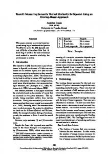
Fig. 1. The design of the BRDF measuring device
of the projection pattern is faster than mechanical rotation, rapid and dense measurement can be achieved. 4.2
Design of the Measuring System
Based on the principle described in the previous section, we developed two BRDF measuring devises that have differently shaped ellipsoidal mirrors. One is a vertical setup in which a target material is placed vertically to the long axis as shown in Fig.1(a). The shape of the mirror is an ellipsoid that is cut perpendicularly to the long axis as shown in Fig.1(c). The other is a horizontal setup in which a target material is placed horizontally to the long axis as shown in Fig.1(b). The shape of the mirror is an ellipsoid that is cut parallel and perpendicularly to the long axis as shown in Fig.1(d). The major optical devices are a projector, a digital camera, an ellipsoidal mirror, and a beam splitter. The illumination from the projector is reflected on the beam splitter and the ellipsoidal mirror, and finally illuminates a single point on the target object. The reflected light on the target object is again reflected by the ellipsoidal mirror, and is recorded as an image. The vertical setup has merit in that the density of the BRDF is uniform along φ because the long axis of the ellipsoid and the optical axes of the camera and projector are the same. Moreover, this kind of mirror is available commercially because it is often used as part of a usual illumination device. However, target materials must be cut into small facets to be placed at the focal point. On the other hand, the horizontal setup has merit in that the target materials do
250
Y. Mukaigawa, K. Sumino, and Y. Yagi φ=0
N incoming
outgoing
θr
θi
φ=60
φ=300 φ=270
φ=90 θ=30 θ=60
φ=240
φr
φ=30
φ=330
φi
(a) Four angle parameters
φ=210
φ=180
φ=150
φ=120
φ=240
φ=300 φ=0 φ=60 θ=90 φ=330 φ=30 φ=90 φ=120 θ=60
φ=270
θ=30
θ=90
(b) Vertical setup
(c) Horizontal setup
Fig. 2. Angular parameters of BRDF. (a) Four angle parameters. (b)(c) Relationship between the angles (θ, φ) and the image location.
not have to be cut. Hence, the BRDF of cultural heritages can be measured. However, the mirror must be specially made by the cutting operation. 4.3
Conversion Between Angle and Image Location
The lighting and viewing directions are specified as angles, while they are expressed as 2-D locations in the projection pattern or the captured image. The conversion between the angle and the image location is easy if geometric calibration is done for the camera and the projector. Figures 2 (b) and (c) illustrate the relationship between the angle and the image location for the vertical and horizontal setup, respectively.
5
Multiplexed Illumination
In this section, the problem of low dynamic range inherent in the projectorbased system is clarified, and this problem is shown to be solved by multiplexed illumination based on the Hadamard matrix. 5.1
Dynamic Range Problem
There are two main reasons for low dynamic range. One of these is the difference in intensities for specular and diffuse reflections. If a short shutter speed is used to capture the specular reflection without saturation, diffuse reflection tends to be extremely dark as shown in Fig.3(a). Conversely, a long shutter speed to capture bright diffuse reflection creates saturation of the specular reflection as shown in Fig.3(b). This problem is not peculiar to our system, but is common in general image measurement systems. The other reason is peculiar to our system that uses a projector for illumination. Generally, the intensity of the black pixel in the projection pattern is not perfectly zero. A projector emits a faint light when the projection pattern is black. Even if the intensity of each pixel is small, the sum of the intensities converging on one point cannot be ignored. For example, let us assume that the contrast ratio of the projector is 1000 : 1 and the size of the projection pattern
brightness
brightness
(a)
angle
(b)
angle
251
Specular Diffuse Sum of black projection
brightness
Multiplexed Illumination for Measuring BRDF
(c)
angle
Fig. 3. The problem of low dynamic range
is 1024 × 768. If 10 pixels in a projection pattern are white and the others are black, the intensity ratio of the white pixels to the black pixels is 10 × 1000 : (1024 × 768 − 10) × 1 = 1 : 79.
(1)
Thus the intensity of the black pixels is larger than one of the white pixels. This means that the measured data include a large amount of unnecessary information which should be ignored as shown in Fig. 3(c). By subtracting the image that is captured when a uniform black pattern is projected, this unnecessary information can be eliminated. As only a few bits are required to express the necessary information, a radical solution is required. 5.2
Multiplexed Illumination
Optical multiplexing techniques from the 1970s have been investigated in the spectrometry field[13]. If the spectrum of a light beam is measured separately for each wavelength, each spectral signal becomes noisy. Using the optical multiplexing technique, multiple spectral components are simultaneously measured to improve the quality. In the computer vision field, Schechner et al.[14] applied the multiplexing technique to capture images under varying illumination. In this method, instead of illuminating each light source independently, the multiplexed light sources are simultaneously illuminated. From the captured images, an image that is illuminated by a single light source is calculated. Wenger et al.[15] evaluated the effects of noise reduction using multiplexed illumination. We briefly describe the principle of multiplexed illumination. Let us assume that there are n light sources, and that s denotes the intensities of a point in the images when each light source turns on. The captured images are multiplexed by the weighting matrix W . The intensities m of the point by the multiplexed illumination are expressed by m = W s. (2) The intensities of the point under the single illumination can be estimated by s = W −1 m.
(3)
In our BRDF measuring system, a projector is used instead of an array of light sources. Hence the weighting matrix W can be arbitrarily controlled. It is
252
Y. Mukaigawa, K. Sumino, and Y. Yagi
known that if the component of the matrix W is −1 or 1, the Hadamard matrix is the best √ multiplexing weight[13]. In this case, the S/N ratio is increased by a factor of n. The n × n Hadamard matrix satisfies H Tn H n = nI n ,
(4)
where I n denotes an n × n identity matrix. In fact, as negative illumination cannot be given by a projector, the Hadamard matrix cannot be used directly. It is also known that if the component of the matrix W is 0 or 1, the S-matrix is the best√ multiplexing weight[13]. In this case, the S/N ratio is increased by a factor of n/2. The S-matrix can be easily generated from the Hadamard matrix. Hence, the projection pattern is multiplexed using the S-Matrix. Since the illumination can be controlled for each pixel using a projector, n becomes a large number and dramatic improvement can be achieved.
6 6.1
Experimental Results BRDF Measuring Systems
We constructed BRDF measuring systems named RCGs (Rapid Catadioptric Gonioreflectometers) as shown in Figs.4 (c) and (d). The RCG-1 includes a PointGrey Flea camera, an EPSON EMP-760 projector, and a Melles Griot ellipsoidal mirror as shown in Fig.4 (a). The RCG-2 includes a Lucam Lu-160C camera and a TOSHIBA TDP-FF1A projector. The ellipsoidal mirror for the RCG-2 is designed so that BRDFs can be measured for all angles of θ within 0 ≤ φ ≤ 240 as shown in Fig.4 (b).
Ellipsoidal mirror
Plate mirror
Object
(a)
(b)
Beam splitter
Projector Camera
(c) RCG-1 (vertical setup)
(d) RCG-2 (horizontal setup)
Fig. 4. The BRDF measuring systems
Multiplexed Illumination for Measuring BRDF
(a) velvet
(b) satin
(c) polyurethane
253
(d) copper
Fig. 5. Target materials
(a)
(b)
(c)
(d)
Fig. 6. BRDF of velvet and satin. (a)(b) examples of captured images, (c)(d) rendering result from measured BRDFs.
6.2
Measurement of Velvet and Satin
In this section, the results of measured BRDFs using the RCG-1 are shown. The target objects are velvet and satin, both of which have anisotropic reflections, as shown in Figs.5(a) and (b). First, the measuring time is evaluated. The sampling interval was set to one degree. The pattern corresponding to the lighting directions θi = 30 and φi = 250 was projected, and the reflected images were captured, as shown in Figs.6 (a) and (b) for velvet and satin, respectively. It is noted that some BRDFs could not be measured because the ellipsoidal mirror of the RCG-1 has a hole at the edge of the long axis. 360 × 90 = 32400 images were captured for each material. The measuring time was about 50 minutes. Figures 6 (c) and (d) are generated images of a corrugated plane that have the measured BRDFs of velvet and satin. The rendering process for this corrugated shape fortunately does not require the missing data. It can be seen that the characteristics of anisotropic reflection are reproduced. 6.3
Measurement of a Polyurethane Sphere
To evaluate the effectiveness of the multiplexed illumination, the isotropic BRDF of a polyurethane sphere was measured as shown in Fig.5(c). In this case, the lighting direction is varied by 1-DOF rotation because of the isotropic reflection. That is, the azimuth angle φi is fixed, and the elevation angle is varied 0 ≤ θi ≤ 180. Figure 7(a) shows an example of multiplexed illumination by a 191 × 191 S-matrix, and (b) shows the captured image after subtracting an image of projecting a black pattern. The captured images of the lighting direction θi = 10, φi = 270 were compared under several conditions. Figures 8(a) and (b) show the distribution of the reflected light without multiplexing. (a) is a single captured image, while (b) is
254
Y. Mukaigawa, K. Sumino, and Y. Yagi
(a)
(b)
Fig. 7. An example of the multiplexed illumination. (a) Projected pattern multiplexed by a 191 × 191 S-Matrix, and (b) the captured image.
(a) Single illumination without averaging
(b) Single illumination with averaging
(c) Multiplexed illumination (d) Multiplexed illumination without averaging with averaging Fig. 8. The reflected light of the lighting direction (θl = 10, φl = 270)
the average of ten captured images. The captured images are very noisy even with the averaging process. Figures 8(c) and (d) show the results with multiplexing. A sequence of multiplexed illumination patterns were projected, and the distribution of the reflected light corresponding to the same lighting direction is estimated. As before, (c) is the result without averaging, while (d) is the result with averaging ten images. Obviously, the noise is dramatically decreased in the multiplexed illumination. To find the spatial distribution of the reflected light, the changes in intensity of y = 60, x = 30 − 200 are plotted as shown in Fig.9. (a) shows the intensities without averaging, while (b) shows those with averaging ten images. In the graphs, blue and red lines represent the distribution with and without multiplexing, respectively. It is interesting that the result of multiplexing without averaging is more accurate than the result of the single illumination with averaging. While the time taken for capturing images is ten times greater for the averaging process, the multiplexed illumination can improve accuracy without increasing the capturing time. Figure 10 shows rendered images of a sphere and a corrugated surface using the BRDF measured by multiplexed illumination with averaging. Compared with the real sphere, the distribution of the specular reflection is slightly wide. One of the reasons is that the reflected light on the ellipsoidal mirror does not converge
Multiplexed Illumination for Measuring BRDF brightness 1.6
255
brightness 1.6 single at once multiplexed at once
1.4 1.2
single average multiplexed average
1.4 1.2
1
1
0.8
0.8
0.6
0.6
0.4
0.4
0.2
0.2
0
0
-0.2
-0.2
-0.4 30 40 50 60 70
80 90 100 110 120 130 140 150 160 170 180 190 200 pixel
(a) without averaging
-0.4 30 40 50 60 70
80 90 100 110 120 130 140 150 160 170 180 190 200 pixel
(b) with averaging ten images
Fig. 9. The distribution of the intensities
(a)
(b)
(c)
(d)
Fig. 10. Rendering results of the pink polyurethane sphere
perfectly on the target material because the alignment of the optical devices is not perfect. Since the target object is a sphere, the normal direction varies if the measuring point is different. As a result, the wide specular reflections may appear to be generated incorrectly. Unnatural reflections were observed in the upper area in Figures 8(c) and (d). This problem may be caused by the cutting operation error of the ellipsoidal mirror. Therefore, the BRDF of θ = 65 is substituted for the missing data of θ > 65. One of our future aims is to improve the accuracy of the optical devices. 6.4
Measurement of a Copper Plate
The isotropic BRDFs of a copper plate were measured as shown in Fig.5(d). Metal is the most difficult material for which to measure the BRDFs accurately, because the intensity levels of specular and diffuse reflections are vastly different. Figure 11 shows the rendering results of a corrugated surface using the measured BRDFs. (a) represents the results of a single illumination, while (b) represents those of multiplexed illumination. Since a fast shutter speed is used when measuring BRDFs to avoid saturation, the captured images are very dark. Hence, the rendering results are brightly represented in this figure. In the rendered images of (a) and (b), incorrect colors such as red or blue are observed. These incorrect colors seem to be the result of magnifying noise during the brightening process. On the other hand, noise can be drastically decreased in the rendered images of (c) and (d) using multiplexed illumination.
256
Y. Mukaigawa, K. Sumino, and Y. Yagi
(a)
(b)
(c)
(d)
Fig. 11. Comparison of the rendered results of the copper plate. (a) and (b) Single illumination. (c) and (d) Multiplexed illumination.
Although the dynamic range of the measured BRDFs is suitably widened, some noise is still observed in the rendered images. Ratner et al.[16] pointed out the fundamental limitation of Hadamard-based multiplexing. The dynamic range problem can also be reduced by incorporating the use of several images captured with varying shutter speeds[17], while the capturing time increases.
7
Conclusion
In this paper, we proposed a new high-speed BRDF measurement method that combines an ellipsoidal mirror with a projector, and solved the low dynamic range problem by applying multiplexed illumination to pattern projection. Two BRDF measuring systems were developed, which include differently shaped ellipsoidal mirrors. The proposed systems can measure complex reflection properties including anisotropic reflection. Moreover, the measuring time of BRDFs can be significantly shortened by the exclusion of a mechanical device. This paper focuses only on the BRDF measuring speed of the developed systems. The accuracy of the measured BRDFs needs to be evaluated. For the evaluation, we are attempting to compare the measured BRDFs and the ground truth using reflectance standards for which reflection properties are known. This research was partially supported by the Ministry of Education, Science, Sports and Culture, Grant-in-Aid for Young Scientists (A).
References 1. Matusik, W., Pfister, H., Brand, M., McMillan, L.: A Data-Driven Reflectance Model. In: Proc. SIGGRAPH 2003, pp. 759–769 (2003) 2. Karner, K.F., Mayer, H., Gervautz, M.: An image based measurement system for anisotropic reflection. Computer Graphics Forum (Eurographics 1996 Proceedings) 15(3), 119–128 (1996) 3. Lu, R., Koenderink, J.J., Kappers, A.M.L.: Optical Properties (Bidirectional Reflection Distribution Functions) of Velvet. Applied Optics 37(25), 5974–5984 (1998) 4. Marschner, S.R., Westin, S.H., Lafortune, E.P.F., Torrance, K.E., Greenberg, D.P.: Image-Based BRDF Measurement Including Human Skin. In: Proc. 10th Eurographics Workshop on Rendering, pp. 139–152 (1999) 5. Li, H., Foo, S.C., Torrance, K.E., Westin, S.H.: Automated three-axis gonioreflectometer for computer graphics applications. In: Proc. SPIE, vol. 5878, pp. 221–231 (2005)
Multiplexed Illumination for Measuring BRDF
257
6. M¨ uller, G., Bendels, G.H., Klein, R.: Rapid Synchronous Acquisition of Geometry and Appearance of Cultural Heritage Artefacts. In: VAST2005, pp. 13–20 (2005) 7. Davis, K.J., Rawlings, D.C.: Directional reflectometer for measuring optical bidirectional reflectance, United States Patent 5637873 (June 1997) 8. Mattison, P.R., Dombrowski, M.S., Lorenz, J.M., Davis, K.J., Mann, H.C., Johnson, P., Foos, B.: Handheld directional reflectometer: an angular imaging device to measure BRDF and HDR in real time. In: Proc. SPIE, vol. 3426, pp. 240–251 (1998) 9. Ward, G.J.: Measuring and Modeling anisotropic reflection. In: Proc. SIGGRAPH 1992, pp. 255–272 (1992) 10. Dana, K.J., Wang, J.: Device for convenient measurement of spatially varying bidirectional reflectance. J. Opt. Soc. Am. A 21(1), 1–12 (2004) 11. Kuthirummal, S., Nayar, S.K.: Multiview Radial Catadioptric Imaging for Scene Capture. In: Proc. SIGGRAPH2006, pp. 916–923 (2006) 12. Han, J.Y., Perlin, K.: Measuring Bidirectional Texture Reflectance with a Kaleidoscope. ACM Transactions on Graphics 22(3), 741–748 (2003) 13. Harwit, M., Sloane, N.J.A.: Hadamard Transform Optics. Academic Press, London (1973) 14. Schechner, Y.Y., Nayar, S.K., Belhumeur, P.N.: A Theory of Multiplexed Illumination. In: Proc. ICCV 2003, pp. 808–815 (2003) 15. Wenger, A., Gardner, A., Tchou, C., Unger, J., Hawkins, T., Debevec, P.: Performance Relighting and Reflectance Transformation with Time-Multiplexed Illumination. In: Proc. SIGGRAPH2005, pp. 756–764 (2005) 16. Ratner, N., Schechner, Y.Y.: Illumination Multiplexing within Fundamental Limits. In: Proc. CVPR2007 (2007) 17. Debevec, P., Malik, J.: Recovering High Dynamic Range Radiance Maps from Photographs. In: Proc. SIGGRAPH1997, pp. 369–378 (1997)