ARTICLES
Multipurpose microfluidic probe DAVID JUNCKER*†, HEINZ SCHMID AND EMMANUEL DELAMARCHE Zurich ¨ Research Laboratory, IBM Research GmbH, 8803 Ruschlikon, ¨ Switzerland *Present address: Micro and Nanosystems, ETH Zurich, ¨ 8092 Zurich, ¨ Switzerland † e-mail:
[email protected]
Published online: 24 July 2005; doi:10.1038/nmat1435
Microfluidic systems allow (bio)chemical processes to be miniaturized with the benefit of shorter time-to-result, parallelism, reduced sample consumption, laminar flow, and increased control and efficiency. However, such miniaturization inherently limits the size of the solid objects that can be processed and entails new challenges such as the interfacing of macroscopic samples with microscopic conduits. Here, we report a microfluidic probe (MFP) that overcomes these problems by combining the concepts of ‘microfluidics’ and of ‘scanning probes’. Here, liquid boundaries formed by hydrodynamic forces underneath the MFP confine a flow of processing solution and replace the solid walls of closed microchannels. The MFP is therefore mobile and can be used to process large surfaces and objects by scanning across them. We illustrate the versatility of this concept with several examples including protein microarraying, complex gradient-formation, multiphase laminar-flow patterning, erasing, localized staining of cells and the contact-free detachment of a single cell. Many constraints imposed by the monolithic construction of microfluidic channels can now be circumvented using an MFP, opening up new avenues for microfluidic processing.
icrofluidic systems are extraordinary in reducing sample consumption, speeding up reaction rates and improving efficiency while allowing for parallelization1–8 . Microconduits form the heart of microfluidic systems in providing the microfluidic space where mass transport is enhanced because of reduced diffusion distances and where laminar flow prevails6–10 . However, high flow resistances, the difficulty of introducing the samples into microconduits and the clogging of the microfluidic systems with samples or impurities limit their practical use. For example, if large surfaces need to be processed, microfluidics become unpractical because for centimetre-long channels the flow resistance is excessively large and does not allow one to flush sufficient quantities of liquids or to exchange solutions within the microchannels. Moreover, large objects, for example, tissue slices, cannot be enclosed within a microchannel and up to now could not be processed with microfluidics. Here, we present an approach where the microfluidic flow is locally created on the sample surface and confined by liquid boundaries in the gap formed between an MFP—described in detail below—and the surface. This approach circumvents the need for inserting the sample into a closed microchannel by replacing solid walls with liquid boundaries that are formed by hydrodynamic forces. Thus, a microfluidic flow can be created locally on any object or surface in a geometrically open space and moved to a random location or scanned along an arbitrary path by moving the MFP. Let us consider a mesa immersed in a fluid that has a microscopic aspiration aperture at its middle. The aspiration of fluid into the aperture will generate a hemispherical flow field around the aperture. Positioning the mesa parallel to a surface defines a gap in which the aspiration of the immersion fluid generates a radial flow field between the two surfaces. If the gap is sufficiently small, it forms a microfluidic space where turbulences are suppressed and the flow field is laminar9 . On adding a second aperture in the mesa, a fluid can be injected into the flow field of the immersion fluid. We define as an MFP a chip with a mesa that has both an aspiration and an injection aperture. A processing solution injected into the gap and aspirated downstream into the aspiration aperture can now be confined entirely if the geometrical parameters as well as the flow rates of both the injected solution and of the aspirated surrounding liquid are properly adjusted. That is, if the injection flow rate (QI ) is
M
nature materials ADVANCE ONLINE PUBLICATION www.nature.com/naturematerials © 2005 Nature Publishing Group
1
ARTICLES QI
a
QA
QA/QI
Processing solution
2.5
4
8
16
4 µm
MFP
3
S
y
z Gap
y Transparent substrate Injection aperture
Mesa b
Aspiration aperture
10 µm
Gap
Surrounding medium 50 µm
L
x
100 µm
W QI
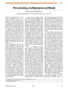
Figure 2 Fluorescence micrographs of patterns of fluorescently labelled proteins deposited on glass using an MFP. The gap between the MFP and the glass surface, the MFP geometry and the ratio QA /QI of the flow rates determine the pattern shape on the surface. The MFP used here had 20× 20 µm2 apertures separated by S = 30 µm and is outlined in the first quadrant, with dotted lines showing the apertures and mesa, a dashed line showing the confinement envelope of the flow and an arrow indicating the flow direction. For increasing gaps, the highest ratio QA /QI for which the microjet still makes contact with the surface decreases. By adjusting the parameters, it is still possible to obtain an effective confinement despite the relatively large gaps.
QA
x y
c
20 µm
Figure 1 MFP and HFC. Sketches of, a, a cross-sectional and b, a bottom view of an MFP in a surrounding medium and over a substrate. The surrounding medium is aspirated into an aperture at a flow rate QA (blue area, blue flow lines) and exerts a hydrodynamic pressure on a stream injected through a second aperture at a rate QI < QA . The stream is deflected, confined and focused into a microjet (green area, red flow lines) and guided into the aspiration aperture. c, Fluorescence micrograph of the apertures in an MFP and of a hydrodynamically confined microjet recorded through a transparent glass substrate for 8 s. The aqueous microjet contained fluorescein (green) and fluorescent beads 2.5 µm wide (red) that show the shape and flow lines, respectively, whereas the surrounding medium (water) appears black. The apertures of the MFP are 20× 20 µm2 , S = 30 µm, the gap is 10 µm, QI = 0.44 nl s−1 and the ratio QA /QI = 2.5, resulting in a relatively wide microjet shape.
sufficiently smaller than the aspiration flow rate (QA ), the injected solution is hydrodynamically deflected and focused into a microjet by the concentric flow field and then directed into the aspiration aperture. Under these conditions, a liquid boundary formed by the surrounding medium confines the injected processing solution. We define this phenomenon as hydrodynamic flow confinement (HFC; Fig. 1). A real-time fluorescence movie of the HFC in a gap formed between the mesa of a microfluidic probe and a substrate surface is shown as Supplementary Information Video S1. HFC bears similarities to hydrodynamic focusing7 because a first fluid is being enclosed and focused by a second one. However, HFC is 2
not constrained by the walls of a microchannel, but occurs instead in a geometrically open space. Therefore, if the ratio QA /QI falls below a critical value, defined as the confinement limit, the confinement is lost and the injected fluid leaks into the surrounding medium. The hydrodynamic focusing strength, which is mainly determined by the ratio QA /QI , can be adjusted, and, for small gaps, the microjet can be forced to impinge on the surface. The variation of QA and QI , in conjunction with the gap size, can be used to fine-tune the shape and size of the impingement area on the surface. Thus, a stream of processing solution can be used to flush the surface and either deposit or remove material locally. The confinement and focusing properties of HFC were analysed experimentally by injecting a solution containing fluorescently labelled proteins that adsorbed on the proximal substrate while systematically varying the ratio QA /QI and the gap between the MFP and the substrate (Fig. 2). Here, the injection rate was kept constant, QI = 0.44 nl s−1 , and only QA was varied. Interestingly, the confinement limit, which is slightly below QA /QI = 2.5, is relatively insensitive to the gap, and the patterns of adsorbed protein are well defined even for gaps larger than the separation distance between the apertures (gap = 50 µm versus separation S = 30 µm). A remarkable feature of HFC is that, even for large gaps, conditions can be found in which the microjet flushes the surface over an area that is smaller than the footprint of the apertures (see Fig. 2, third row and fourth column). The dimensionless Reynolds number Re is a measure of the ratio between inertial forces and viscous forces11 and is defined as 2RH · ρ · v , Re = η where RH is the hydraulic radius, ρ is the density of the liquid, v is the average flow speed and η is the viscosity. The value Re = 2,000 is the empirical limit between laminar flow (Re < 2,000) and turbulent flow (Re > 2,000). The calculated flow speed for a large gap of 50 µm, and 1.1 nl s−1 aspiration flow rate (the minimum value used in the experiments shown here) is 275 µm s−1 at the edges of the aspiration aperture and, for S = 30 µm, is 59 µm s−1 at the far edge of the injection aperture. The corresponding Reynolds
nature materials ADVANCE ONLINE PUBLICATION www.nature.com/naturematerials © 2005 Nature Publishing Group
ARTICLES a
Clamping rod
Clamping screw
Clamped Si chip
Microposts
b
Glass capillaries
Mesa Bonded PDMS connection block
100 µm
Figure 3 Manipulation of an MFP using a slender clamping rod. a, Close-up view of the MFP, composed of a microfabricated 3× 7 mm2 silicon chip with a bonded PDMS block that together form the probe head, an aluminium manipulator rod and glass capillaries for the transport of liquids. The silicon chip features a large central mesa with the injection and aspiration apertures. The PDMS block has two openings for receiving the fused-silica glass capillaries, which are simply plugged in. The PDMS forms a tight liquid seal. Below the PDMS, microchannels guide the liquid towards the injection and aspiration apertures etched vertically through the silicon chip. The silicon chip is clamped at the edges with an aluminium manipulator rod such that the mesa and the four microposts are the most salient structures. The microposts serve as mechanical buffers to prevent damage to the mesa in the event of a contact with the processed surface. b, Micrograph of the mesa of an MFP showing the two 20× 20 µm2 apertures, which are separated by 30 µm here. The width of the mesa is ∼220 µm and its elevation varies between 20 and 50 µm depending on the chip.
numbers are Re = 0.017 and Re = 0.08 at the aspiration aperture and at radius r = 60 µm, respectively, and these corroborate the experimental observations of laminar-flow conditions. The P´eclet number is a measure of the convective versus diffusive transport12 and helps one evaluate whether diffusion can broaden the hydrodynamically confined microjet: Pe =
2RH v , Dn
where Dn is the diffusion constant of the solute; the lower the flow speed, the larger the broadening. In our case, the lowest aspiration flow rate was QA = 1.1 nl s−1 . The average flow speed in the concentric flow field generated between the mesa and substrate by the aspiration flow from the outside towards the inside equals the flow rate divided by the annular cross-section. The injection flow rate can be considered as a local perturbation and is neglected in this calculation. The cross-section A of the channel at the aspiration aperture is the perimeter of the aperture (4 × 20 µm) multiplied by the gap G = 50 µm, that is, 4 × 103 µm2 . The cross-section increases linearly with increasing distance from the aspiration aperture and takes the value of the circular perimeter for radius r multiplied by the gap G. The larger the gap and the radius, the larger the cross-section (and the slower the flow), which at the far edge of the injection aperture (for S = 30 µm and r = 60 µm) is 1.88 × 104 µm2 . For the two cross-sections discussed above, the average flow speeds are 275 and 59 µm s−1 , respectively. The hydraulic radius is defined as RH = 2A/P where P is the perimeter. The perimeter takes the value of 2 × 2πr , corresponding to the perimeter of the circle on the substrate and on the mesa of the MFP. There are no lateral sidewalls and the perimeter is therefore equivalent to that of a slit of length 2πr. Interestingly, we find that here RH = G and, because v = f (G−1 ), Pe is independent of the gap G for HFC. For IgGs with a typical diffusion constant Dn = 4 × 10⁻¹¹ m2 s−1 , the P´eclet number is Pe = 690 at the aspiration aperture and Pe = 147 at r = 60 µm. The convective
500 µm
50 µm
Figure 4 Fluorescence micrograph of a protein array that was patterned using an MFP. The array features 1,384 spots spaced 80 µm apart and was written with the microjet flowing from bottom to top, as in Fig. 2. The upper elements of each block were designed as segments (connecting two spots) for demonstration purposes. One protein was a TRITC-labelled goat IgG (red) and the other a rabbit IgG. After completion of the array, rabbit antibodies were stained with FITC-labelled anti-rabbit IgG (green). The inset shows the high quality of the sites, where no drying artefacts can arise. Some of the artefacts on the right of the array (green) are attributed to contact between the MFP and the substrate, which is due to the microscopic size of the gap and the unevenness of the glass slide over such a large area.
transport is more than two orders of magnitude larger than the diffusive transport, which therefore does not markedly enlarge the microjet. The experimental conditions used here are characterized by low Reynolds and high P´eclet numbers, which both contribute to the efficient confinement of the microjet and inhibit diffusion of solute from one stream to the other6 . The confinement of the microjet and solutes remains efficient even for a gap of 50 µm. The dimension of the smallest spots reflects the size (20 µm) and separation of the two apertures, and may in principle be reduced further by simply reducing these dimensions. The laminar flow below the MFP under these experimental conditions is such that the flow path of a particle from a specific location within the dispensing aperture to the aspiration aperture is quasi-deterministic. These properties are consistent with analysis of the flow using finiteelement-model calculations (T. Hocker, unpublished results). The simultaneous injection and aspiration of a solution for processing under immersion conditions is not new in itself, and has been applied for many years in physiology for in vivo perfusion and sampling using dual glass pipettes13,14 . There, the goal is to perfuse the brain regardless of diffusive leakage; for surface processing, however, the confinement of the dispensed solution is crucial15 . The geometry of pipettes is however not linear (they are concentric), which precludes the formation of a liquid boundary
nature materials ADVANCE ONLINE PUBLICATION www.nature.com/naturematerials © 2005 Nature Publishing Group
3
ARTICLES a
c
b
500 µ
m
100 µm
80 µm Proteins removed from surface
Figure 5 Advanced surface processes enabled by using an MFP. a, Fluorescence intensity profile of a 4× 4 array of fluorescently labelled proteins deposited on a glass surface with a surface-density gradient. The MFP was first moved from left to right to form one gradient, then quickly shifted one line down, then from right to left and so on. The gradient of proteins on the surface reflects the velocity gradient of the MFP. b, Fluorescence micrograph of a dodecahedron written using FITC-labelled IgGs (rabbit) that precipitated at the interface between the laminar microjet and the immersion medium. c, Localized removal of material from a substrate using an MFP. The fluorescence micrograph reveals TRITC-labelled goat IgGs that were first adsorbed homogeneously onto a glass slide from solution, and subsequently removed from specific areas using a stream of solvent solution delivered using an MFP. The MFP was displaced along a pattern similar to that in Fig. 4.
with the focusing properties that characterize HFC. Thus, the pattern produced with pipettes is much larger than the size of the dispensing aperture and the fluid is easily leaked as a result of a displacement in any direction. In contrast, the laminar flow field of HFC defined between the two co-planar surfaces of the MFP mesa and the substrate produces a strong focusing that allows the writing of arbitrary patterns with sharp contrast by drawing the MFP across the surface as if it were a pen. Consequently, we manipulated the MFP using a slender clamping rod (Fig. 3). Unlike a pen, the MFP operates in proximity to the surface (without mechanical contact), in a surrounding medium, and with a continuous delivery and removal of reagents. The injection–aspiration of the processing stream and the wide gap between the MFP and the surface during operation sets it apart from other scanning probe lithography approaches16–19 . Another important difference between MFP and other approaches is the magnitude and importance of hydrodynamic effects that come into play when moving the MFP because of the co-planar geometry. When the substrate is scanned relative to the MFP (which is what we usually did), a laminar drag, a so-called Couette flow20 , develops between the mesa of the MFP and the surface, and is superposed on the concentric flow field. Controlled use of this effect allows the processing of isolated areas of a surface with a simple stop-and-go movement. Indeed, when the substrate is moved in the direction of the microjet flow, the microjet is viscously dragged towards the aspiration aperture. At the same time, the surface boundary layer of immersion liquid forms a barrier layer during the brief passage under the microjet and protects the surface from the microjet. A high-density array of antibodies was swiftly formed on a glass by taking advantage of these hydrodynamic phenomena (Fig. 4). Excerpts of the computer-controlled procedure are shown in real time in the Supplementary Information Video S2. The array was ‘spotted’ with a high throughput using a single MFP programmed to diagonally align the elements of the pattern while leaving some areas unpatterned. The two first spots of each block in the array are connected by one back-and-forth movement. When the substrate is moved against the direction of the microjet, the Couette flow opposes the flow direction of the microjet. Moderate velocities broaden the space enclosed by the liquid boundaries, and molecules in the microjet can adsorb to the surface and, as shown 4
here, connect two spots. Thus, without requiring a valving system for interrupting the flow and without a need to retract the MFP, each protein subarray was patterned in less than 15 min with ∼300 nl of solution and with a final surface density of >15,000 spots cm−2 . Each spot was formed in 0.3 s, using only 130 pl of solution. A 2–5 µm gap between the MFP and surface to ensure a high mass transport and a rapid adsorption of the proteins to the surface were key to these figures of merit. Compared with conventional spotting techniques such as pin-spotting and drop-on-demand (that is, the inkjet technique)21 , the sample consumption of the MFP is similar, whereas the spot uniformity and density are superior. With the conventional techniques the droplets are left on the substrate without control, tend to spread on deposition, then stagnate, and evaporate because they are in contact with air. The results are relatively ill defined aggregates of biomolecules on surfaces22 that nevertheless have important applications in biology and medicine, as shown by numerous experiments done using biochips. In contrast, patterning using an MFP does not expose them to drying effects, which yields high-quality spots and enables sequential flushing with different reagents to carry out highly reproducible biological assays8,23 . The processing of large objects and surfaces, or of molecules bound to large surfaces within a microfluidic space, is evidently highly desirable and is now possible using an MFP. Many processes that were impossible to perform have become feasible with an MFP, whereas others that were difficult and inefficient have become much easier and more efficient. In the following sections, we present five additional and distinct examples of advanced processes that were enabled or enhanced by the introduction of the MFP. Microscale gradients are useful for optimizing reaction conditions24,25 , and for studying cell behaviour and migration in response to a surface gradient (haptotaxis)26 and to a stationary gradient in solution (chemotaxis)27 —for instance in recent experiments on the differentiation of human stem cells28 . These applications are however limited by the necessity of having closed, complex microfluidic systems that are required to create even relatively simple microscale gradients24,25,27,28 . The continuous variation of the scanning velocity of the MFP represents an alternative for adjusting the density of proteins adsorbing to a
nature materials ADVANCE ONLINE PUBLICATION www.nature.com/naturematerials © 2005 Nature Publishing Group
ARTICLES a
a
b 0 min
Selected cell MFP
Substrate
c
d 4 min
8 min
b
20 µm
100 µm
Figure 6 Contact-free processing of selected adherent cells performed using an MFP under immersion conditions. a, Differential interference contrast image of fixed fibroblast cells. An MFP was used to locally treat the cells and is represented by a scheme to scale with the injection and aspiration aperture. A red shaded area represents the confined microjet that contained 100 µg ml−1 of fluorescent dye (DiI). b, Fluorescent micrograph of the same area as in a, showing the cells that were labelled with dye. The MFP was moved so as to write ‘CELLS’; the passage from one letter to the next was done without interrupting the flow simply by a rapid movement of the MFP, which was sufficient to avoid staining of the underlying cells. The joystick-controlled procedure was completed within three minutes. The inset is a composite image of the interference contrast image and the fluorescent micrograph that shows the shape and the distribution of dye in the cells.
surface and for forming continuous microscale gradients. For slow velocities, the microjet flushes the surface for sufficient time to saturate it with proteins, but with increasing velocity the density of adsorbed protein becomes lower. Here, we patterned a ‘microarray’ of 16 surface gradients, each ∼500 µm long, by varying the velocity of an MFP (with a separation of 240 µm between the two apertures) continuously 16 times in series at 16 distinct locations (Fig. 5a). The MFP was displaced perpendicularly to the flow direction and the velocity controlled manually using a joystick. With this method, the composition, geometry and slope of the gradient can be varied arbitrarily by adjusting the velocity and many gradients can be produced rapidly side by side on a single substrate, as is illustrated by the gradient array. The MFP thus offers additional flexibility for the design and the rapid making of multiple gradients compared with closed microfluidic systems, while achieving similar resolutions. A reaction between two substances dissolved in two adjacent, parallel laminar streams is naturally localized close to the interface6,7 and has been used for the microfabrication of metallic wires within microchannels29 . Such a reaction can also be produced using HFC. We created a laminar flow with two phases to precipitate fluorescently labelled proteins that were dissolved in the microjet (5 mM sodium acetate buffer, pH 6.0) at the interface to the surrounding medium (deionized water). We found that the amount of precipitation on the surface could be adjusted by varying the ratio QA /QI , the gap between surface and MFP, and by displacing the
Figure 7 Selective detachment and collection of a single living cell from a surface. a, Schematic cross-section of the MFP, the flow lines and cells (an outline of the microjet is shown in c). b, A single, adherent fibroblast cell within a cell culture was selected (black arrow) and detached from the substrate by flushing a jet containing 1.25% of trypsin (and fluorescein for visualization) over the cell. The surrounding medium was a physiological solution supporting the growth of the cells. Images b–d show the initial state of the cell, the cell in a contracted form and the surface after detachment of the cell, respectively. The neighbouring cells were still adherent after 20 min of fluid aspiration into the MFP, indicating that trypsinization remained local.
MFP; the direction of displacement could either enhance or reduce the precipitation when moving along or against the direction of the microjet flow, respectively. The displacement of the MFP thus leaves a trail of precipitated proteins on the surface, which we used to draw lines in the shape of a dodecahedron (Fig. 5b). The prominent ridges were written by moving the substrate in the direction of the microjet and show a thin, bright precipitation pattern corresponding to the position below the aspiration aperture that is superposed on the wider pattern corresponding to the footprint of the microjet. The faint, hidden edges were drawn moving into the direction opposite to that of the microjet, with a larger gap, a higher speed and a greater ratio QA /QI . Instead of the surrounding medium, a second microjet, dispensed through a second aperture and flowing parallel to the first microjet, might form the second phase and define a linear interface of precipitation running from the two adjacent injection apertures to a single aspiration aperture. The width of the precipitation line is a function of flow velocity, diffusion constants and reaction rates, and may be considerably less than the size of the apertures29 . Each microjet injected into the laminar flow field of HFC forms a local perturbation, and if there are multiple injected microjets they may affect one another; the operation conditions for a specific application using many microjets in parallel may thus lie within a narrow process window and may require optimization by numerical modelling and by experimentation. Using an MFP with either one or multiple microjets, arbitrary lines of precipitated material of variable thickness may be drawn using metals29 , biopolymers and possibly electrically conducting and semiconducting polymers, and may for example be laid out as functional electrical circuits30 . In contrast to conventional wet-patterning techniques, the MFP can also be used in subtractive processes29 , as is illustrated by the desorption of adhering proteins from a glass slide—Fig. 5c and Supplementary Information Video S3—exemplifying the concept
nature materials ADVANCE ONLINE PUBLICATION www.nature.com/naturematerials © 2005 Nature Publishing Group
5
ARTICLES of ‘erasing’. The injected processing solution had a high pH, contained a surfactant and contained a high concentration of salt, all of which contributed to the rapid detachment of the proteins from the surface. The MFP can thus be used for both ‘positive’ and ‘negative’ patterning. The negative patterning may be extended to etching a substrate and to removing any soluble substance—and even non-soluble ones, as will be shown below. The efficient focusing of the microjet by HFC with large gaps is essential for the contactless processing of cells in culture (which do not form an ideal planar surface) with single-cell resolution, and can for example be used for local staining (Fig. 6). An MFP with 40 × 40 µm2 apertures separated by 24 µm was positioned 15–20 µm above a substrate covered with fixed cells, and used to flush a solution containing a carbocyanine dye that labels cell membranes by inserting its two long (18 carbon atoms) hydrocarbon chains into the lipid bilayers. The selective detachment and collection of a single living cell from a surface is also possible (Fig. 7). An MFP was used to flush a solution containing trypsin over an adherent fibroblast cell. Trypsinization is a standard technique for hydrolysing cell-adhesion peptides and for retrieving cells that are cultured on a surface, but one that hitherto had only been used on the whole-culture scale, which is typical of conventional cell-handling procedures. The two examples above demonstrate the delivery of a bio(chemical) with high spatial resolution above a single cell and indicate the applicability of this approach to the study of cell dynamics, chemotaxis, cell polarity, spatially and temporally regulated signalling, drug screening and so on31 , with the benefit of a local microfluidic space, yet without the need to abandon well established cell culture procedures. Many phenomena that occur within a microfluidic space and which so far could only be studied within solid, closed microchannels can now be created and observed in a geometrically open space, and exploited for new purposes. We have hence extended microfluidics to lithography, with both the ‘writing’ and ‘erasing’ modes, to collecting cells and to controlling reactions locally at liquid–liquid and liquid–solid interfaces, using ‘open’ laminar-flow processes. There are additional processing possibilities, such as first detaching selected substances or objects from surfaces and then depositing them at a new location, for example, on a sensor surface, by simply reversing the aspiration flow. The multipurpose MFP may also be enhanced further, for example by including a distance sensor32 or by integrating multiple, higher-resolution injection and aspiration apertures. We hypothesize that the future applications of the MFP and laminar-flow processing will be not only in biology, as illustrated by the examples in this work, but also in physics, chemistry and materials sciences. The MFP probably provides a serious alternative to the inkjet technique for patterning delicate organic layers used in polymer electronics and displays30,33 . We suggest that this work is a starting point for the development and use of multipurpose MFPs in various areas of science and engineering.
METHODS MFP FABRICATION The MFPs were fabricated in double-side-polished silicon wafers (Siltronix, Geneva, Switzerland) using photolithography and a deep-reactive-ion etcher (AMS200, Alcatel) in a three-step procedure similar to the one described in ref. 34. Diced MFP chips were bonded with a poly(dimethylsiloxane) (PDMS) interface block before use. The silicon chip was affixed to a rod, Fig. 3, and mounted on the z-axis. The substrate area to be processed was covered with a few millilitres of solution (surrounding medium) and the MFP lowered into this solution to a position corresponding to the desired gap. Two syringe pumps were connected through fused-silica glass capillaries to the silicon chip and were used to control QI and QA . Because of the low flow rates used, replenishment of solution proved unnecessary, except to compensate for evaporation. The PDMS interface block was fabricated by casting PDMS (Sylgard 184, Dow Corning, Midland, Michigan) into a micromould composed of two structured poly(methyl methacrylate) (PMMA) elements, a polished steel plate forming the bottom, and two capillaries (each inserted into one of the two vias—access holes—in the steel plate) serving as place holders for the fluidic connection holes. The PDMS was cured in an oven at 60 ◦ C for at least 1 h. The PDMS block was bonded to a silicon chip by activating both parts in air plasma (100-E, Tepla, Feldkirch, Germany), at 1 mbar for 24 s at 230 W, and joining the two together using a home-made mechanical alignment aid.
6
EXPERIMENTAL SETUP Liquid flow was driven by syringe pumps (Genie, Kent Scientific) mounted with syringes (Hamilton) having capacities of 1 and 10 µl for injecting and aspirating, respectively. The syringes were connected with adapters and finger-tight fittings (Upchurch Scientific) to fused-silica glass capillaries with 360 µm outer diameter and with 50 and 100 µm internal diameters. At the other end, the capillaries were inserted into the PDMS interface block of the MFP. A home-made carrier was mounted onto the inverted microscope. Two motorized axes (Limes 90, OWIS, Germany) were used for positioning the carrier in x and y, and one axis was used for positioning for the MFP in z. The axes were computer controlled (L-step, OWIS, Germany). The substrate (usually a glass slide) was clamped into the home-made carrier using two leaf springs. The horizontality of the substrate was adjusted using micrometer screws arranged in a three-point support configuration on the carrier. The mesa of the MFP was also aligned with the substrate by means of an adjustable tilt stage (Melles Griot).
IMAGING SETUP AND PROCEDURES The flow fields and patterns were viewed using an inverted microscope (Eclipse TE300, Nikon). Images were recorded either with a cooled, low-noise CCD (charge-coupled device) camera (Sensicam, PCO, Germany) or a ‘consumer’ camera (Nikon Coolpix 990, Sony DCR-PC 330E, used for obtaining both still images and videos) for colour images. Larger areas were imaged using a microarray scanner (BA4F, Lavision-Biotec, Germany). Black-and-white images were coloured and joined together digitally (Image Pro 5, Media Cybernetics, USA).
EXPERIMENTAL PROCEDURES Chemicals were from Fluka and proteins from Sigma, unless otherwise indicated. In the experiments shown in Fig. 2, goat immunoglobulin G (IgG) labelled with fluorescein isothiocyanate (FITC, green) was dissolved in phosphate buffer saline (PBS, BupH, Pierce) at 1 mg ml−1 and an APTS glass slide was used as the substrate. In Fig. 3a, a hydrogel-coated slide (HCX, Xantec GmbH, Germany) served as the substrate. This slide featured an NHS-activated carboxylated hydrogel. Proteins in solutions with low pH and salt concentration first adsorb to the carboxylated groups of the hydrogel and subsequently react with the NHS group of the gel matrix. IgGs labelled with tetramethylrhodamine isothiocyanate (TRITC, red) were prepared as a 3 mg ml−1 solution in 10 mM phosphate buffer, pH 6.0, and flushed in the microjet across the substrate. The same buffer also served as the surrounding medium. Non-labelled anti-goat rabbit IgGs were patterned using the same concentration and buffers. After quenching the NHS groups, the slide was incubated for 30 min with 200 µg ml−1 FITC-labelled anti-rabbit goat IgGs in PBS buffer containing 1% bovine serum albumin (BSA). After thorough rinsing and drying according to the manufacturer’s specifications, the slide was imaged. For the gradient array of Fig. 4b, 1 mg ml−1 TRITC-labelled goat IgGs were dissolved in 10 mM phosphate buffer, pH 6.0, which also served as the surrounding medium. The dodecahedron of Fig. 4c was drawn with FITC-labelled goat IgGs dissolved in 5 mM acetate buffer, pH 6.0, and with water as the surrounding medium. The prominent edges of the polyhedron were drawn with a gap of 10 µm with varying velocities and with manual interruption of the flow. To generate the homogeneous fluorescent protein layer patterned in the experiment of Fig. 5a, a hydrogel-coated slide (HC, Xantec, Germany) was activated according to the manufacturer’s specifications and incubated for 15 min with 1 mg ml−1 TRITC-labelled goat IgGs in 10 mM phosphate buffer, pH 6.0. The proteins were then selectively removed with a microjet of 0.1 M carbonate buffer at pH 11.5 with 1 M NaCl and 0.2% Triton-X, and with 50 µg ml−1 fluorescein for flow visualization. Fibroblast cells (NIH 3T3 line) were kept under standard culturing conditions in Dulbecco’s modified Eagle’s medium (DMEM) containing Glutamax I (GIBCO Life Technologies) and sodium pyruvate, supplemented with 10% heat-inactivated fetal bovine serum (Sigma Aldrich) and 1% antibiotic/antimycotic solution (GIBCO Life Technologies). The cells were plated on glass coverslips at least 24 h before the experiments at a seeding density of approximately 10,000 cells cm−2 . For the experiment, the same medium, but without the serum supplement, was used to cover the adherent cells. The working stage had been enhanced with heating mats and temperature sensors to adjust the temperature on the glass slide. A PBS microjet containing 1.25% trypsin and 0.02% EDTA, as well as 1 µg ml−1 fluorescein for visualization, was used to detach the fibroblast cells adhering to the cover slip.
Received 16 March 2005; accepted 20 May 2005; published 24 July 2005. References 1. Nguyen, N. -T. & Wereley, S. T. Fundamentals and Applications of Microfluidics (Artech House MEMS Series, Artech House, Boston, 2002). 2. Reyes, D. R., Iossifidis, D., Auroux, P. -A. & Manz, A. Micro total analysis systems. 1. Introduction, theory, and technology. Anal. Chem. 74, 2623–2636 (2002). 3. Auroux, P. -A., Reyes, D. R., Iossifidis, D. & Manz, A. Micro total analysis systems. 2. Analytical standard operations and applications. Anal. Chem. 74, 2637–2652 (2002). 4. Hansen, C. & Quake, S. R. Microfluidics in structural biology: smaller, faster ... better. Curr. Opin. Struct. Biol. 13, 538–544 (2003). 5. Kopp, M. U., de Mello, A. J. & Manz, A. Chemical amplification: continuous-flow PCR on a chip. Science 280, 1046–1048 (1998). 6. Hatch, A. et al. A rapid diffusion immunoassay in a T-sensor. Nature Biotechnol. 19, 461–465 (2001). 7. Knight, J. B., Vishwanath, A., Brody, J. P. & Austin, R. H. Hydrodynamic focusing on a silicon chip: mixing nanoliters in microseconds. Phys. Rev. Lett. 80, 3863–3866 (1998). 8. Juncker, D. et al. Autonomous microfluidic capillary system. Anal. Chem. 74, 6139–6144 (2002). 9. Brody, J. P., Yager, P., Goldstein, R. E. & Austin, R. H. Biotechnology at low Reynolds numbers. Biophys. J. 6, 3430–3441 (1996). 10. Delamarche, E. et al. Microfluidic networks for chemical patterning of substrates: design and application to bioassays. J. Am. Chem. Soc. 120, 500–508 (1998). 11. Streeter, V. L., Wylie, E. B. & Bedford, K. Fluid Mechanics 9th edn 260–262 (McGraw-Hill, Singapore, 1998). 12. Stroock, A. D. et al. Chaotic mixer for microchannels. Science 295, 647–651 (2002). 13. Myers, R. D. An improved push-pull cannula system for perfusing an isolated region of the brain. Physiol. Behav. 5, 243–246 (1970). 14. Kottegada, S., Imtiazuddin, S. & Shippy, S. A. Demonstration of low flow push-pull perfusion. J. Neurosci. Methods 121, 93–101 (2002). 15. Feinerman, O. & Moses, E. A picoliter ‘fountain-pen’ using co-axial dual pipettes. J. Neurosci. Methods 127, 75–84 (2003). Erratum. ibid 128, 197 (2003). 16. Meyer, E., Hug, H. J. & Bennewitz, R. Scanning Probe Microscopy: The Lab on a Tip (Springer, Berlin, 2004). 17. Bard, A. J. & Mirkin, M. V. Scanning Electrochemical Microscopy (Marcel Dekker, New York, 2001). 18. Ginger, D. S., Zhang, H. & Mirkin, C. A. The evolution of dip-pen nanolithography. Angew. Chem. Int. Edn Engl. 43, 30–45 (2003). 19. Bruckbauer, A. et al. Multicomponent submicron features of biomolecules created by voltage controlled deposition from a nanopipet. J. Am. Chem. Soc. 125, 9834–9839 (2003). 20. Kundu, P. K. & Cohen, I. M. Fluid Mechanics 2nd edn 274–277 (Academic, San Diego, California, 2002). 21. Rose, D. in Microarray Biochip Technologies (ed. Schena, M.) 19–38 (Eaton Publishing, Natick, Massachusetts, USA, 2000).
nature materials ADVANCE ONLINE PUBLICATION www.nature.com/naturematerials © 2005 Nature Publishing Group
ARTICLES 22. McQuain, M. K., Seale, K., Peek, J., Levy, S. & Haselton, F. R. Effects of relative humidity and buffer additives on the contact printing of microarrays by quill pins. Anal. Biochem. 320, 281–287 (2003). 23. Wolf, M., Juncker, D., Michel, B., Hunziker, P. & Delamarche, E. Simultaneous detection of C-reactive protein and other cardiac markers in human plasma using micromosaic immunoassays and self-regulating microfluidic networks. Biosen. Bioelectron. 19, 1193–1202 (2004). 24. Caelen, I. et al. Formation of gradients of proteins on surfaces with microfluidic networks. Langmuir 16, 9125–9130 (2000). 25. Fosser, K. A. & Nuzzo, R. G. Fabrication of patterned multicomponent protein gradients and gradient arrays using microfluidic depletion. Anal. Chem. 75, 5775–5782 (2003). 26. Smith, J. T. et al. Measurement of cell migration on surface-bound fibronectin gradients. Langmuir 20, 8279–8286 (2004). 27. Jeon, N. L. et al. Neutrophil chemotaxis in linear and complex gradients of interleukin-8 formed in a microfabricated device. Nature Biotechnol. 20, 826–830 (2002). 28. Chung, B. G. et al. Human neural stem cell growth and differentiation in a gradient-generating microfluidic device. Lab on a Chip 5, 401–406 (2005). 29. Kenis, P. J. A., Ismagilov, R. F. & Whitesides, G. M. Microfabrication inside capillaries using multiphase laminar flow patterning. Science 285, 83–85 (1999). 30. Sirringhaus, H. et al. High-resolution inkjet printing of all-polymer transistor circuits. Science 290, 2123–2126 (2000).
31. Takayama, S. et al. Selective chemical treatment of cellular microdomains using multiple laminar streams. Chem. Biol. 10, 123–130 (2003). 32. Oberti, S., Stemmer, A., Juncker, D., D¨urig, U. & Schmid, H. Microsqueeze force sensor useful as contact-free profilometer and viscometer. Appl. Phys. Lett. 86, 063508 (2005). 33. Shimoda, T., Morii, K., Seki, S. & Kiguchi, H. Inkjet printing of light-emitting polymer displays. Mater. Res. Soc. Bull. 28, 821–828 (2003). 34. Juncker, D. et al. Soft and rigid two-level microfluidic networks for patterning surfaces. J. Micromech. Microeng. 11, 532–541 (2001).
Acknowledgements We thank U. Drechsler and R. Stutz for technical assistance, W. Riess, B. Michel and M. Despont for discussions, T. Hocker for performing finite-element-model simulations, G. Csucs ´ for providing the cells and P. F. Seidler for support. Correspondence and requests for materials should be addressed to D.J. Supplementary Information accompanies this paper on www.nature.com/naturematerials.
Competing financial interests The authors declare that they have no competing financial interests.
nature materials ADVANCE ONLINE PUBLICATION www.nature.com/naturematerials © 2005 Nature Publishing Group
7