IEEE TRANSACTIONS ON IMAGE PROCESSING, VOL. 7, NO. 9, SEPTEMBER 1998
1283
Multiresolution 3-D Range Segmentation Using Focus Cues Changhoon Yim, Member, IEEE, and Alan C. Bovik, Fellow, IEEE
Abstract—This paper describes a novel system for computing a three-dimensional (3-D) range segmentation of an arbitrary visible scene using focus information. The process of range segmentation is divided into three steps: an initial range classification, a surface merging process, and a 3-D multiresolution range segmentation. First, range classification is performed to obtain quantized range estimates. The range classification is performed by analyzing focus cues within a Bayesian estimation framework. A combined energy functional measures the degree of focus and the Gibbs distribution of the class field. The range classification provides an initial range segmentation. Second, a statistical merging process is performed to merge the initial surface segments. This gives a range segmentation at a coarse resolution. Third, 3-D multiresolution range segmentation (3-D MRS) is performed to refine the range segmentation into finer resolutions. The proposed range segmentation method does not require initial depth estimates, it allows the analysis of scenes containing multiple objects, and it provides a rich description of the 3-D structure of a scene. Index Terms—Bayesian estimation, depth-from-focus, multiresolution range segmentation, 3-D segmentation.
I. INTRODUCTION
T
HE OBJECTIVE of segmentation is to partition an image or scene into homogeneous regions [1]. In intensity image segmentation, regions are discovered using properties of the image intensity levels [2], [3]. In range image segmentation, regions are computed from range values [2], [4], [5]. The purpose of range image segmentation is to obtain more compact and structured descriptions of surfaces and objects for interpreting range images. In previous range image segmentation methods, it has generally been assumed that the range data is already available from some range finding techniques (e.g., laser range finder, stereo). These range image segmentation methods require the range information as prior knowledge and have generally been limited to applications involving small depth ranges. Recently much research has been applied to the problem of computing surface depths from focus cues [6]–[14]. Focus Manuscript received February 7, 1997; revised November 11, 1997. This work was supported by the Army Research Office under Contract DAAH 049510494. The associate editor coordinating the review of this manuscript and approving it for publication was Prof. Jeffrey J. Rodriguez. C. Yim was with the Laboratory for Vision Systems, Department of Electrical and Computer Engineering, The University of Texas at Austin, Austin, TX 78712-1084 USA. He is now with the HDTV and Multimedia Laboratory, Sarnoff Corporation, Princeton, NJ 08543-5300 USA (e-mail:
[email protected]). A. C. Bovik is with the Laboratory for Vision Systems, Department of Electrical and Computer Engineering, The University of Texas at Austin, Austin, TX 78712-1084 USA (e-mail:
[email protected]). Publisher Item Identifier S 1057-7149(98)06388-X.
is an attractive source for depth information, since it has no correspondence problem as in stereo [15]. Focus cues can be efficiently used for measuring depth when the initial ranges are not available, for example, in a multimodal active vision system. However, most methods use focus cues for measuring depth at just one image point or for recovering a depth map only for a single object. Little research has been performed on the extended three-dimensional (3-D) reconstruction problem of computing multiple depth ranges or multiple object surfaces using focus cues. In this paper, we consider simultaneous range segmentation and 3-D reconstruction using focus cues. The range segmentation strategy partitions a scene into 3-D regions having different depth ranges, in order to produce a description of the 3-D structure of the objects in the scene, using focus information, without requiring initial depth estimates of the objects. The proposed range segmentation method unfolds into three steps: an initial range classification process, a merging process, and finally, a 3-D multiresolution range segmentation strategy. Each stage of the algorithm is developed within a Bayesian statistical framework, as summarized next. The approach taken here computes depth from multiple camera focus positions. The number of focus positions is necessarily limited, and so we first perform a range classification stage to obtain quantized range estimates from focus information. Correct range estimates are difficult to obtain from a finite set of focus positions. In [16], we proposed a range classification algorithm using focus cues in a multiresolution framework. Here we extend this work by casting the problem as a Bayesian estimation problem. The approach is related to the work of several previous authors. Geman et al. [17] proposed a statistical framework for partitioning images into homogeneous regions. They employed a Markov random field (MRF) to model image fields. An important feature of the MRF’s is that the conditional distribution of a site in the field, given all other sites, is only dependent on its neighbors. By the MRF-Gibbs equivalence property [17]–[19], the probability that the MRF is in a certain state can be calculated using the local energies. It is a Bayesian approach, and it provides a maximum a posteriori (MAP) estimate for range classification. The MRF statistical framework has been effectively utilized in many image classification and segmentation methods [17]–[28]. We perform range classification by combining two paradigms: focus cues and Bayesian estimation [29]. A criterion function computed from focus information provides
1057–7149/98$10.00 1998 IEEE
1284
IEEE TRANSACTIONS ON IMAGE PROCESSING, VOL. 7, NO. 9, SEPTEMBER 1998
a basic method for measuring the distribution of ranges in each region of a scene. A Bayesian estimate is obtained by modeling the class field as a Markov random field. An energy functional of the Gibbs distribution of the class field is defined using the MRF-Gibbs equivalence property. To combine these two paradigms, we define a combined energy functional in terms of the energy functional from the criterion function values for focus measure and the energy functional of the Gibbs distribution of the class field. The combined energy functional is minimized by a modified simulated annealing method which yields the range classification. The range classification provides quantized range estimates. After the range classification stage, we define initial surface segments as connected 3-D surface regions having the same range class values. Hence, the range classification also provides an initial range segmentation. Once the range classification is performed, it becomes possible to construct cohesive surfaces through a merging process, which combines the initial segments from the range classification result. This gives a 3-D range segmentation at a coarse resolution. In the merging process, we use Gaussian Markov random fields (GMRF’s) to model the 3-D vectors of each surface segment. GMRF models have been frequently used for the segmentation of texture images [20], [25], [28], and color images [27]. Finally, we complete and refine the range segmentation taken from the merging process, via a 3-D multiresolution range segmentation (3-D MRS). Multiresolution techniques have been efficiently used for many image segmentation methods [3], [18], [19]. In this final stage, we use multiresolution Markov random fields to model the field of segment indices, range classes, and the 3-D vectors in the surface segments. Using the MRF-Gibbs equivalence relationship, we define energy functionals using segment indices and the 3-D vectors. We also define an energy functional using the criterion function values. A combined energy functional is defined as the weighted summation of these energy functionals, which are constructed over multiple resolutions. The proposed 3-D MRS algorithm first performs range segmentation at the coarsest resolution and proceeds progressively to finer resolutions. The proposed range segmentation method does not require initial depth estimates, and it provides a rich description of the 3-D structure of a scene. II. DEPTH
FROM
FOCUS CUES
For a thin lens, if a point on an object is focused, then the Gaussian lens law holds [6], [9], [12], [15]: (1) is the distance of the point from the lens, is the where image plane distance from the lens, and is the focal length of the lens. According to geometric optics, the intensity within the blur circle is approximately a constant. However many factors must be accounted for to get a more accurate modeling of the blurring function. These factors include diffraction effects, sampling errors from digitization, and chromatic aberration
[13], [30]. It has been frequently argued that net effect is effectively described by a two-dimensional (2-D) Gaussian function [7], [11]–[13], [30], [31]: (2) where is a spread parameter which controls the amount of defocusing. can be modHence, a blurred or defocused image and eled as the linear convolution of a focused image [6], [7], [12], [13], [31]: a Gaussian function (3) From (3), if an image is defocused, then it is lowpass filtered, and high-frequency components in the image are removed or deemphasized. Thus a defocused image will have a smaller amount of high-frequency content than a focused image of the same scene [6]. Hence, in principle, it should be possible to find the focused image by computing the high-frequency content of multiple images taken at different focus positions. After the focused image and the corresponding image plane can be calculated from distance are found, the distance (1). To measure the high-frequency contribution, we need a criterion function that is maximized for the focused image. In (1), the distance is a continuous function of the image To make the problem feasible, we plane distance for quantize in a finite number of steps, meaning that we grab a finite number of images with different image plane distances. Then is also quantized into a finite number of steps. Focus cues yield depth measurements over each image region. The comparison is performed on each image region using different images taken with different image plane distances. By finding the image that maximizes a criterion function, it is possible to estimate the depth of that image region from (1). Krotkov proposed measuring depth using focus cues at a single image point [9]. Krotkov searches the image plane distance that creates an exact focus by a Fibonacci search strategy. The critical problem of Krotkov’s approach is that it can find the depth at only a single image point. This is very limited information, and furthermore, we do not have any prior knowledge about what point at which to measure the depth. Darrel and Wohn [6] developed a depth from focus method using an image sequence of a scene by varying the image plane distance. They build Gaussian and Laplacian pyramids in the calculation of depth. As a criterion function for focus measure, they use the absolute value of the Laplacian image. After the Laplacian pyramid is generated, the associated absoluteLaplacian criterion function from the multiple images having different image plane distances are compared in order to compute a depth estimate. Nayar and Nakagawa propose getting a dense depth map from focus [11], [12]. They use several images with different focus positions as in Darrel and Whon [6]. In their approach, the focal setting is modified by varying the object distance instead of image plane distance of (1). The experimental results include single objects displaying microscopic texture and a very small range of depth. They propose the summodified-Laplacian as a criterion function in their experiments
YIM AND BOVIK: MULTIRESOLUTION 3-D RANGE SEGMENTATION
1285
[11], [12]. The peak focus point is estimated by a Gaussian interpolation method. The method appears effective for shape reconstruction over a small depth range, but has not been demonstrated on scenes containing multiple objects or over a large range of depths. Subbarao and Choi recently proposed a shape-from-focus method that is based on a focused image surface concept [14]. The focused image surface of an object is defined as the surface formed by the set of points at which the object points are focused. In their experiments, they used a sequence of images taken using different image plane distances to reconstruct the shape of an object. This method also assumes a single object surface, and is dependent on the assumption that the images contain sufficient high-frequency content everywhere in the scene to measure the focus accurately. Regions missing the necessary high frequency content result in computed surface errors. Little research has been performed on the problem of 3D reconstruction involving multiple objects or multiple depth ranges, using focus cues. Here we consider range segmentation using focus cues. The objective of range segmentation is to partition a scene into 3-D regions with different depth ranges to produce a description of the 3-D structure of the scene involving multiple objects, without initial estimates of object depths.
To measure the amount of remaining high-frequency components, we propose to use a highpass function defined in by the frequency domain
(6) Since the function has a shape complementary to that of a Gaussian, we call this function the anti-Gaussian function. We argue that the anti-Gaussian function effectively measures the high-frequency content after the defocusing operation be the anti-Gaussian filtered image is performed. Let Then for a defocused image (7) is the inverse Fourier transform of Note where that we propose (6) as a method for capturing high frequencies, not as a mechanism to strictly invert the blur. That is, we do not seek that A highpass filtered image can be computed as the difference between the original image and a lowpass filtered version of the image. Multiplying the original image by an amplification factor and then subtracting the lowpass image from it yields a high-boost filter [1]: (8)
III. CRITERION FUNCTION FOR FOCUS MEASURE A defocused image is modeled as the convolution of a focused image and a lowpass filter function as in (3). To find the focused image and subsequently measure depth, a criterion function is required to assess the degree of high-frequency content over the spans of images taken with different focus positions. Krotkov compared several criterion functions experimentally [9]. The functions studied are the Tenengrad (the sum of the gradient magnitude), the sum of the magnitude of Fourier transform, certain types of highpass filtering, histogram entropy, and the sum of modulus difference. Krotkov concluded that of these, the Tenengrad gives the best result. Now consider the defocusing operation of (3) in the freLet and quency domain represent the Fourier transforms of and respectively. Then (4) If we model the lowpass filter function for defocusing as a Gaussian function in (3), then (5) is increased, the system is more In (4) and (5), as defocused. Hence, a focused image retains its high-frequency components while a defocused image loses them. An effective criterion function for focus measure should quantify the remaining high-frequency content after the defocusing operation is performed as in (4).
The general process of subtracting a blurred image from an original, as expressed in (8), is called unsharp masking [1]. The anti-Gaussian filter implements the highpass filter by subtracting the Gaussian filtered version of the image from the original image. Hence, the anti-Gaussian filter is a kind of unsharp masking where the lowpass filter is the Gaussian filter and the amplification factor is 1 in (8). High frequencies are emphasized at the expense of lower frequencies, but in a controlled manner. For a focus measure, we propose to use a spatial summation of the squared anti-Gaussian filtered images. We call this function sum-square-anti-Gaussian (SSAG) function. The SSAG in function for measuring the degree of focus of a region an image is defined as for
(9)
is a threshold value. This threshold operation is where performed to reduce noise effects and is also performed in other criterion functions (e.g., Tenengrad [9]). When a region contains adequate high-frequency content (e.g., edge or texture regions), the focus measure function effectively assesses the amount of high-frequency content in images taken at different focus positions. In such cases, the criterion function becomes large and yields reliable range estimates. However, when a region contains a small amount of high-frequency content, it is difficult to compare the highfrequency content between images at different focus positions, due to noise effects. This effect becomes more severe as the region size is reduced.
1286
IEEE TRANSACTIONS ON IMAGE PROCESSING, VOL. 7, NO. 9, SEPTEMBER 1998
(a) Fig. 1.
(b)
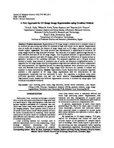
Two images of an image sequence with eight different focus positions. (a) I3 : (b) I7 :
IV. RANGE CLASSIFICATION A. Range Classification: Problem with different Assume that we take images image plane distances. The object distance from the lens can be calculated from the image plane distance by the Gaussian lens law (1). In practical situations, we do not obtain depth by (1) because we do not know the real image plane distance accurately. It is preferable to build a look-up table for depth corresponding to each image plane location. If we take images with different image plane distances, we obtain the depths experimentally. To compute range corresponding from focus, we obtain the index yielding the best among the images, instead of finding the range directly. We call this index the range class value. We can obtain quantized depth or range from the range class value. Now consider a region in the set of images. The process to one of the range of range classification maps a region Let and represent class values in the real depth and the estimated depth value of region respectively. represent the range class value of region Then Let and in range classification. In other words, if a region has a range class from the range classification, then the region has value Hence, depth is quantized in the estimated depth value the range classification process. denote the criterion function values of the th Let image. Range quantization using focus cues is computed as (10) Thus, the range class value of region is found by comparing for thus the criterion function values providing an initial range classification. Region is defined to be focus measurable, if it satisfies (11) If region is focus measurable, then we can find the correct range class value of just using the criterion function values, i.e., using focus cues, and there is no difficulty obtaining range classification using focus cues. In this case, we can simply
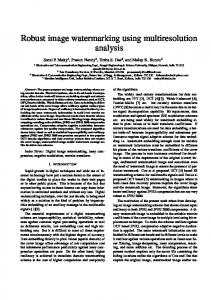
perform range classification from the range quantization using focus cues as in (10). If a region does not contain enough high-frequency content, then this region may not be focus measurable. This case typically occurs at homogeneous regions in images. In practice, many regions in the scene are not focus measurable. Now we show some examples of range classification through range quantization using focus cues. Range quantization using focus cues is defined in (10). In these examples, we collect eight images defined by eight different focus positions, i.e., with different image plane distances. These images are labeled as Fig. 1 shows two of these images with different focus positions. We perform range quantization using different criterion functions in different resolutions, i.e., in different region sizes. We show range quantization examples using two kinds of criterion functions for focus measure: Tenengrad and SSAG. We perform range quantization in several region sizes. Among them, we show range quantization results in two region sizes: 32 and 16 16. Fig. 2(a) and (b) show the range 32 quantization results in regions of 32 32 pixel blocks using Tenengrad and SSAG, respectively. Fig. 2(c) and (d) show 16 pixel the range quantization results in regions of 16 blocks using Tenengrad and SSAG, respectively. In Fig. 2, each region represented by each distinct gray level corresponds to one range class. In these results, we can see that no criterion function for focus measure gives perfect range quantization results at any resolution. As the region size becomes larger, we obtain more robust range quantization result while losing resolution. On the other hand, as the region size becomes smaller, errors in range quantization increase significantly. From these examples, we conclude that there are limitations on range classification through range quantization just using focus cues. We need a new approach to solve this problem. We propose a statistical approach, which uses the posterior distribution of range classes. It employs an MRF model to achieve range classification. B. Statistical Model for Range Classification Let represent a field of the focus criterion function values for the th image. Let represent a field of range classes. Then
YIM AND BOVIK: MULTIRESOLUTION 3-D RANGE SEGMENTATION
1287
(a)
(b)
(c)
(d)
Fig. 2. Range quantization using different criterion functions in different region sizes. (a) Tenengrad (32 (16 16). (d) SSAG (16 16).
2
2
points or sites in take values in the set where is the number of classes. This value corresponds to the number of images with different focus positions. For an MRF, the conditional We use an MRF to model distribution of a site in the field given all other sites is only dependent on its neighbors. In order to define an MRF, the be the set neighborhood system must first be defined. Let be the set of neighbors of a of neighbors of site and site with coordinate We will use a four-neighborhood system in which the are given by neighbors of coordinate
The four-neighborhood system is also known as the first-order is a subset of or nearest-neighbor system [17]. A clique then and sites in such that if and are two points in are neighbors [18], [17]. so that We assume a common state space for all Let be the set of all possible configurations. A Gibbs distribution is a probability measure on with the following representation:
The energy function
2 32). (b) SSAG (32 2 32). (c) Tenengrad is defined as [17], [18]: (13)
is a function where denotes the set of cliques for with the property that depends only on those on of for which Such a family coordinates is called a potential. The MRF-Gibbs equivalence property [17]–[19] provides a simple and practical way of specifying MRF’s. The probability that the MRF is in a certain state can be calculated using the local energies. By the MRF-Gibbs equivalence, if is formulated as a Gibbs distribution, then will have the properties of an MRF. Since we use the four-neighborhood system, the only cliques in the energy function for are pairs of horizontally and vertically adjacent sites. The unless is a clique, in which potentials, case (14) Then (15)
(12) is a normalizing constant, and is the temperature where is called the energy function. [17], [19].
is a constant. We set where four-neighborhood system, is normalized so that functional
In the Then the energy
1288
IEEE TRANSACTIONS ON IMAGE PROCESSING, VOL. 7, NO. 9, SEPTEMBER 1998
is the energy functional defined by the MRF modeling of This measures the similarity of range classes across the image space. represent the criterion function value of site Let assuming range class From the criterion function values, we can find the most likely range class value of site as (16) Equation (16) represents the range quantization using focus cues as in (10). This is the basic rule for measuring ranges be the maximum criterion function using focus cues. Let i.e., values of site
Then is the desired criterion function value satisfying (16). by the criterion funcWe define an energy functional tion values (17) is normalized so that The energy functional This functional has the minimum value 0 when i.e., is the class value that has the maximum is the value in the criterion function value at site energy functional defined by the criterion function values. This measures the degree of closeness to good focus. in (15), (17), we From the energy functionals define the combined energy functional (18) is where is a constant between zero and one. Then The combined energy also normalized so that has information both from the class field functional defined by the MRF and from the field of criterion function values. The value in (18) determines the weight on the energy and As the value is increased, there functionals and less will be more weight on the energy functional and vice versa. As weight on the energy functional explained in Section III, larger criterion function values are more reliable data for measuring focus. Using this information, we assign the value in an adaptive fashion. We assign the value of of site based on the maximum criterion function of site as (19). value
C. Modified Simulated Annealing Simulated annealing is a kind of stochastic relaxation method for minimizing an energy function as a function of the state [18]. It works by generating a chain of these is found by allowing the states. The minimum of temperature to fall slowly as the chain is generated. Standard simulated annealing algorithm begins in an arbitrary state and then successively generates candidate state at time transitions at random [32]. Given the state one randomly chooses another configuration and computes A transition is the energy change accepted with the following probability: if otherwise. As the temperature is decreased, the probability of transition is decreased. the state at site is a random variable At time with values in For generating samples, we use the Gibbs sampler [17]. In a Gibbs sampler, only one site undergoes a and can possible change at each epoch, so that be the sequence differ in at most one coordinate. Let in which the sites are visited for replacement. The sequence that is actually used is the one corresponding to a raster scan [17]. As a result, all sites are visited at each iteration. Instead of visiting all sites as in standard simulated annealing, only selected sites are visited at each iteration. In doing so, we define stable sites and unstable Only unstable sites are visited for replacement at each iteration. In the range classification algorithm, we define two types of stable sites. First, if the maximum value of the criterion in function value of site is greater than the threshold then this site is deemed stable. Second, if (19), i.e., a site has the same class value as all of its neighbors, i.e., for all then the site is also regarded as stable. The first case uses the criterion function values. As explained in Section III, large criterion function values are reliable data for measuring focus. The second case uses the If the class values of neighbors of MRF model of field is minimum only site are the same, then the energy is the same as these values. Assume that when for all Then
(19) is a threshold. The value is chosen large enough where of site such that if the maximum criterion function value is greater than then the range quantization by (16) value provides a reliable range classification. However, if is chosen too large, then the values will become small, and the combined energy functional is mainly dependent on in (18). The range classification is obtained by minimizing over all configurations It is a nonlinear optimization problem that can be solved with relative efficiency using a modified simulated annealing method.
If a site is not stable, then it is defined to be unstable. In the modified simulated annealing method, only unstable sites are visited at each iteration, and unstable sites are updated after each iteration. If the number of unstable sites is decreased at each iteration, the amount of computation for the simulated annealing process is greatly reduced. The initial state supplied to the simulated annealing process is often of critical importance [18]. In standard simulated annealing, the initial state is frequently assigned at random. In modified simulated annealing for range classification, the initial state of the classes of sites is determined by (16).
YIM AND BOVIK: MULTIRESOLUTION 3-D RANGE SEGMENTATION
1289
V. MERGING PROCESS
(21)
The range classification provides an initial range segmentation. After the range classification is performed, a merging process is performed to create surface segments, thus yielding a 3-D range segmentation at a coarse resolution. In the merging process, we use 3-D vectors in a world coordinate system (WCS). The 3-D vectors in the WCS are obtained using the 3-D mapping process given in Section V-B. For the merging process, we use a GMRF to model the field of 3-D vectors of a segment. The approach taken is similar to those taken for the successful segmentation of texture images [20], [25], [28] and color images [27]. A. Range Interpolation The range class values from the range classification process provide quantized range estimates. In the merging process, we use interpolated range values instead of quantized range values to attain greater range resolution. To obtain interpolated range values, we require an appropriate interpolation operation. Nayar and Nakagawa use Gaussian functions to interpolate the criterion function values [12]. They express the criterion function using the Gaussian model. The Gaussian interpolation method [12] uses only three criterion and when is the best function values, focused image. Subbarao and Choi interpolated range values by quadratic and cubic polynomial fitting [14]. They also use three criterion function values. For the interpolation using three criterion function values, we should first obtain the index for best focusing, i.e., the range class value. Here, we use cubic spline interpolation to interpolate the criterion function values. First, the cubic spline interpolation is performed to interpolate the criterion function values. Then the location that has the maximum value among the interpolated criterion function values gives the interpolated range value. This method uses all the criterion function values for the range interpolation. We can apply this method even though the range class value is not available. In range interpolation, if a site is not focus measurable, we assign the average value of the range values of the neighborhood having the same range class value. B. 3-D Mapping from Ranges represent the coordinates of (3-D) vectors Let with respect to the center point of the camera position in a represent row world coordinate system (WCS), and let and column coordinates in the sequence of images. Let represent the image coordinates with respect to the center point and represent the in the image plane of the camera. Let number of pixels in the images in the horizontal and vertical and be the image plane directions, respectively, and size of the camera in the horizontal and vertical directions, and respectively. Then the relationship between is (20)
There is a minus sign in (21) because the row coordinate values in the images are indexed from top to bottom. The and is relationship between (22) is the focal length of the camera. where given the image We have estimates of the object distance values can be plane distance as explained in Section II. The preestimated and stored as a look-up table for the range values. and to By (20)–(22), the mapping functions from are (23) (24) C. Statistical Model for Merging Process GMRF’s are a special case of Markov random fields [27], [33]. GMRF models have been extensively used for the segmentation of texture images [20], [25], [28]. Recently, Panjwani and Healey used the GMRF model for the segmentation of textured color images [27]. In this paper, a criterion for the merging process is developed as a similarity measure between segments using the GMRF model. The GMRF is defined from the conditional probability density function of each segment. denote a 3-D Let vector representing a location in a WCS at image coordinate In and correspond to and respectively, in the WCS of Section V-B. Let denote in segment If then the field of represents the 3-D vector at in segment We model as a GMRF. or represent a 3-D vector in segment Let Let and denote the mean of and in segment respectively. represents the conditional probability density in segment and it has the Gaussian function of distribution
(25) is a zero mean where denotes the correlation Gaussian random vector and where in segment Each component of matrix of for is defined as
(26)
where the where
’s are the model parameters and denotes the set of neighbors of coordinate
1290
IEEE TRANSACTIONS ON IMAGE PROCESSING, VOL. 7, NO. 9, SEPTEMBER 1998
If we use the four-neighborhood system, then The ’s in (26) are the model parameters representing the weights on the and neighborhood information of the 3-D vectors in the directions, respectively. We assume the same weights on the and neighborhood information of the 3-D vectors in the directions. Hence, we set where for Let
be the expected value of Then
(27) in segment
for
(28) is a diagonal matrix. For the GMRF model, let Note that be the vector of the and the parameters in segment D. Merging Criteria and Algorithm The criterion that we use for merging is based on the pseudolikelihood and bears resemblance to the approach used by Panjwani and Healey for color texture image segmentation [27]. For a segment modeled by a GMRF, the pseudolikelihood is given by of segment
(29) is the product of the conditional The function probability densities of the 3-D vectors in segment Let represent the initial surface segments and be two adjacent from the range classification. Let be a segment obtained by merging segments, and let and We model and by GMRF’s and respectively. Let with parameter vectors be the ratio of the pseudolikelihood before the merge and the pseudolikelihood after the merge. Then
(30) This equation is simplified to (31) is near one, this indicates that If the value of have similar 3-D vectors For the convenience of computation, a function defined as
and is (32)
Since
is a diagonal matrix,
can be simplified [27] to
(33) represents the determinant of and and where represent the cardinality of segments and respectively. The merging criteria that we use are as follows. First, segments for merging should be spatially adjacent. Second, segments for merging should be adjacent in their range class values. Third, the log of the pseudolikelihood ratio for merging should be less than a threshold. The segment pairs satisfying all these three criteria are to be merged. The conditions for the first and second criteria can be easily obtained from the coordinate values and the range class values of segments. The condition for the third criterion is obtained by the GMRF model of each segment. The pseudolikelihood ratio represents the similarity of 3-D vectors between segments. The merging algorithm can be summarized as follows. 1) Find and number initial segments. 2) Find the cardinality of each segment. in each segment by 3) Calculate each component of of each segment by (28). (26), and 4) For each pair of segments, check whether it satisfies the first and second criterion. 5) For each segment pair that is found in 4), calculate the log of the pseudolikelihood ratio by (33), and determine whether it is to be merged by the third criterion. 6) Perform the merging for each segment pair to be merged. In 1), each segment is defined as a connected region in images having the same range class values. The order of numbering is arbitrary. We numbered the segments from the segment with lower range class values to the segment with higher range class values. VI. 3-D MULTIRESOLUTION RANGE SEGMENTATION The merging process provides a 3-D range segmentation at the coarsest resolution. To refine the range segmentation into finer resolutions, we perform a 3-D MRS. For 3-D MRS, we use multiresolution Markov random fields to model the field of surface segment indices, range classes and the 3-D vectors in segments. Using the MRF-Gibbs equivalence, we define energy functionals using segment indices and the 3-D vectors. We also define an energy functional using the criterion function values. A combined energy functional is defined as the weighted summation of these energy functions. The combined energy functional includes information from the criterion function values, the segment indices and the 3-D vectors. To create a multiresolution framework, the energy functionals are defined over multiple resolutions. Threedimensional range segmentation is performed over multiple resolutions by a coarse-to-fine strategy. A. Statistical Model for 3-D MRS The 3-D MRS algorithm begins the process of range segmentation at the coarsest resolution and uses the result as
YIM AND BOVIK: MULTIRESOLUTION 3-D RANGE SEGMENTATION
1291
an initial condition for range segmentation at the next finer resolution. The initial state of the 3-D MRS is obtained by the merging process performed at the coarsest resolution. In a multiresolution framework, each resolution corresponds to a level in a quad tree. A lattice point at one resolution corresponds to four points at the next finer resolution. The mapping from pixel coordinates at the th resolution level to th level can be formally points at the previous coarser written as [18] (34) denotes the floor function. Also, will denote where with itself times. the composition of the function denotes the field of range classes at resolution level Sites in take values in the set where is denotes the field of segment the number of range classes. If there are segments, sites indices at resolution level take values in the set The number of in is obtained after the merging process. segments denotes the field of the criterion function values of the th image at resolution level represents the criterion function value of the range class value of site at level Then (35) is the set of sites at the next finer resolution where which map to This means that the criterion function value at can be represented as the summation of the criterion level function value at level Let denote the 3-D vector in The value of the 3-D vector WCS of site at level depends on the value of and it can be represented as a function of In denotes the object distance or the depth range. represent the object distance of site with segment Let Then index value
Here and correspond to and respectively, in the WCS in Section V-B. Hence and can be calculated from and the coordinate value of site by the 3-D mapping method. Let denote the field of the 3-D vectors We use multiresolution MRF’s to model and at each level We define energy functionals under the Bayesian framework at each level. From the criterion function values, we can find the range of site as class value (36) Let at level
be the maximum criterion function value of site i.e., (37)
The energy functional function values at level
of site is defined as
from the criterion
(38) in the denominator is for normalization. Then is normalized so that By the MRF-Gibbs equivalence, the probability distribution is formulated as a Gibbs distribution. Let of field represent the potential functional of site at level The unless is a clique, in which potentials, case
where
(39) The energy functional is of
defined by the MRF modeling (40)
where
is a constant at level We set Then is normalized so that
Let represent the potential functional of at level The potentials unless is a clique, in which case, (41) represents the Euclidean norm. Hence, where is a Euclidean distance between site and site where is a clique. from the 3-D vector The energy functional at level is defined as the MRF modeling of
by (42)
where
is a normalization factor. We set
as (43)
is also normalized so that Then, The combined energy functional is defined as
at level (44)
where with
and
are constants between zero and one (45)
Then
is also normalized so that
The (for values in (44) determine the weight on the energy functionals and As the value becomes larger, there will be more weight on the while less weight on other energy energy functional is the energy functional defined by the functionals. criterion function values measuring the degree of closeness to good focus. As explained in Section III, larger criterion
1292
IEEE TRANSACTIONS ON IMAGE PROCESSING, VOL. 7, NO. 9, SEPTEMBER 1998
function values are more reliable data for measuring focus. The values are selected adaptively using the criterion function of site based value information. We assign the value of of site on the maximum criterion function value
(46)
where
is a threshold at level
The threshold value is determined to be proportional Since the size to the number of pixels in a block at level is the number of pixels in a of a block at level is The threshold value block at level at level can be represented in terms of the threshold value at level (0): (47) Let
where
is a constant between zero and one. Then
The value determines the weight on the energy functionals and and this value can be assigned arbitrarily. This means that we assign In experiments, we set from the 3-D more weight on the energy functional from the segment vectors than on the energy functional indices. B. 3-D MRS Algorithm The optimization criteria we use for finding the best range is segmentation at level (48) the state of site The state represents the We call We assume range class value and segment index of site a common state space so that for all Let be The range the set of all possible configurations at level is obtained by minimizing segmentation at level over all configurations It is an optimization problem, and we solve it by the modified simulated annealing method at each level. In the multiresolution range segmentation algorithm, we use the state information from the previous level and from the neighbors. To use the state information from the previous level, the initial state of range classes and segment indices at each level is obtained by replicating the state of the previous level: (49) Then
Hence, the initial condition of
is obtained as (50)
and values are to be calculated from and The the coordinate value of site In standard simulated annealing for optimization, the state of a site undergoes a random change at each epoch. If there are segments and range classes, there are possible states for each epoch. To use the state information of the neighbors, the state of each site is to be changed to only one neighbor state at each epoch in the modified simulated annealing. For can be changed to only one of with site The 3-D MRS algorithm can be summarized as follows. and the 1) Determine the coarsest resolution level finest resolution level 2) Compute for the levels . 3) Perform the range classification at level 4) Perform the merging process at level 5) Perform the 3-D multiresolution range segmentation at Set level 6) Compute an initial state for and from and for each block. set 7) Compute through the minimization of (44) by If the modified simulated annealing method at level stop. Otherwise, return to 6). VII. EXPERIMENTAL RESULTS The range segmentation method described in this paper was implemented using a camera system named Texas Active Vision Testbed (TAVT). The TAVT was built for active vision research using two cameras, and is described in [34]. Since the depth-from-focus method uses single camera, we use one of these two cameras for image acquisition. The image acquisition hardware employs Panasonic WV-CD 50 CCD camera with a nominal pixel resolution of 480 512 pixels. The RS-170 analog video signal leaving the camera is digitized using a Datacube Digimax framegrabber with an acquisition rate of 1/30 s for a full video frame. The lens used in this research is the Nikon SLR grade lens. The focal length of the lens is 35 mm. The experiments were performed using C programming language on a Sun Workstation. We experimented with this range segmentation method on several scenes containing multiple depth ranges. For each scene, we use an image sequence with eight different image plane distances. These images are labeled as We first make the images into blocks. In these experiments, 32 blocks. In other words, we use level 5 as we use 32 the coarsest resolution level. The criterion function values are computed in each block of each image by (9). The threshold in (9) is determined experimentally as a small value value to reduce the noise effects, and the same value is used in all the experiments. Fig. 1 shows two images of an image sequence with eight different focus positions. This scene contains multiple objects with multiple depth ranges. Fig. 3(a) represents the initial
YIM AND BOVIK: MULTIRESOLUTION 3-D RANGE SEGMENTATION
1293
(a)
(c)
(b)
(d)
Fig. 3. (a) Range quantization using focus cues. (b) Range classification result. (c) Interpolated range values. (d) 3-D display of the interpolated range values.
range classification through the range quantization using focus cues as (16). There are some range classification errors in regions that have small high-frequency content such as in homogeneous regions. Fig. 3(b) shows the range classification result. In Fig. 3(a) and (b), each region represented by each distinct gray level corresponds to one range class. Fig. 3(c) represents the interpolated range values by the cubic spline interpolation method. For blocks that are not focus measurable, we assigned the average value of the range values of the neighborhood having the same range class value. Fig. 3(d) represents the 3-D display of the 3-D vectors obtained from the interpolated ranges in Fig. 3(c). In Fig. 3(d), the arrow represents the viewing direction of the camera to the 3-D space. Fig. 4(a) shows the 3-D display of the initial range segmentation from the range classification result. Each segment is displayed by different symbols. Fig. 4(b) shows the initial Each segment is a range segmentation result displayed on connected region in images having the same range class values. The object at the right side is located in two range classes in the range classification and is composed of four segments in the initial range segmentation. Fig. 4(c) is the 3-D display of the range segmentation result after the merging process. Fig. 4(d) shows the range segmentation result displayed on
In Fig. 4(c), we can see how the objects are located in the WCS and segmented into different objects or different depth ranges. This gives a description of the 3-D structure of a scene. Fig. 4(d) shows that objects in different depth range are segmented into different segments. Note that the object at the right side, which is located in two range classes in the range classification and is composed of four segments in the initial range segmentation, is merged into one object in the merging process. This result is obtained at a coarse resolution 32 blocks. using 32 To refine the segmentation into finer resolutions, we perform the 3-D MRS described in Section VI. In the 3-D MRS, we and Fig. 5(a) represents the 3-D set display of the final 3-D MRS result at level 2. In the 3-D MRS, range segmentation and 3-D reconstruction is performed simultaneously. Fig. 5(b) shows the corresponding 3-D MRS result at level 2 displayed on In this result, there are some errors in the computed boundary shapes. There are two reasons for these errors. These are the insufficiency of the amount of high-frequency content in some locations (that are not focus measurable) and the geometrical distortion arising in defocused images. High-frequency content is the most important information for range classification and for range segmentation using
1294
IEEE TRANSACTIONS ON IMAGE PROCESSING, VOL. 7, NO. 9, SEPTEMBER 1998
(a) (a)
(b) (b) Fig. 5. (a) Three-dimensional display of final 3-D MRS result at level 2. (b) Final 3-D MRS result at level 2 displayed on I3 :
(c)
(d) Fig. 4. (a) Three-dimensional display of the initial range segmentation from the range classification result. (b) Initial range segmentation displayed on I3 : (c) Three-dimensional display of the range segmentation result after the merging process. (d) Range segmentation result displayed on I3 :
focus information. High-frequency content contributes to the criterion function values for focus measure. The criterion function values are used in the range quantization, in the range classification and in the 3-D MRS steps. If a region is homogeneous and does not contain a sufficient amount of high frequency content, then this region can create errors in the range quantization, in the range classification and in the 3-D MRS steps. If this region is surrounded by regions having the same range classes, then the error in the range quantization would be corrected in the range classification step, because the energy functional defined by the MRF model contains the range class information of the neighborhood. However, if this region is located in the boundary area between different range classes, then the error in the range quantization may not be corrected in the range classification. Similarly, if a region does not contain a sufficient amount of high-frequency content and is located in the boundary area between different segments with different ranges, then this region might be segmented incorrectly in the 3-D MRS. This effect becomes more severe as the region size becomes smaller, i.e., as the resolution level becomes lower. Once an error has occurred in the 3-D MRS at a high level, then this error would be propagated to the corresponding regions at lower levels. In Fig. 3(b), most errors in the range quantization are corrected in the range classification except at one block in the middle. This block corresponds to the “table” below the “bunny” having the same range class as
YIM AND BOVIK: MULTIRESOLUTION 3-D RANGE SEGMENTATION
(a)
1295
(b)
(c)
(d)
(e)
(f)
(g)
(h)
(i)
Fig. 6. (a) One image of an image sequence with eight different focus positions. (b) Range quantization using focus cues. (c) Range classification result. (d) 3-D display of the initial range segmentation. (e) Initial range segmentation displayed on I3 : (f) Range segmentation result after the merging process displayed on I3 : (g) 3-D display of the final 3D MRS result at level 2. (h) Final 3-D MRS result at level 2 displayed on I3 : (i) Final 3-D MRS result at level 2 displayed on I7 :
the background in Fig. 1. This block does not contain sufficient high-frequency content and is located in the boundary area of different range classes. The region corresponding to this block is also incorrectly segmented in the 3-D MRS. Because this region contains small high-frequency content and is located on the boundary area of different segments with different depth ranges, errors are propagated to the following lower levels. Fig. 6(a) shows one image of an image sequence taken with eight different focus positions. Fig. 6(b) represents the initial range classification through the range quantization process. There are some classification errors in regions that have little high-frequency content such as in homogeneous regions. Fig. 6(c) shows the range classification result. Note
that the object at the lower left side is located in four range classes. Fig. 6(d) shows the 3-D display of the initial range segmentation from the range classification result. Each segment is displayed by different symbols. Fig. 6(e) shows the initial range segmentation result displayed on The object at the lower left side is composed of four segments. Fig. 6(f) shows the range segmentation result after the merging Note that the object at the lower process displayed on left side, which is located in four range classes in the range classification, is merged into one object in the 3-D merging process. Fig. 6(g) represents the 3-D display of the final 3-D MRS result at level 2. Fig. 6(h) shows the corresponding 3-D MRS result at level 2 displayed on
1296
IEEE TRANSACTIONS ON IMAGE PROCESSING, VOL. 7, NO. 9, SEPTEMBER 1998
(a)
(b)
(c)
(d)
(e)
(f)
Fig. 7. (a) One image of an image sequence with eight different focus positions. (b) Range classification result. (c) 3-D display of the initial range segmentation. (d) Initial range segmentation. (e) Range segmentation result after the merging process. (f) Final 3-D MRS result at level 2.
There are geometrical distortions in defocused images [6], [13]. The geometrical distortions are due to the magnification effect of a lens system. Because of geometrical distortion, point locations in images for the same object point in the WCS may not be the same if the image plane distances are different. Hence image features are shifted in images with different image plane distances by the geometrical distortion. The use of larger windows or larger regions for focus measure would reduce the geometrical distortion problem at the cost of decreased spatial resolution [10]. In Fig. 6(h), the boundary shape between the upper part of the radio and the background looks a little shifted. The boundary is slightly shifted to the inside of the radio in most areas, and the boundary is located at the correct position in just a few places. These errors are due to the geometrical distortion. Fig. 6(i) shows the range In Fig. 6(i), the segmentation result at level 2 displayed on boundary is located at the correct position in most places, and is slightly shifted to the outside of the radio in a few spots, contrary to the case in Fig. 6(h). Fig. 7 shows another experimental result. Fig. 7(a) shows of an image sequence with one image, different focus positions. In this scene, the object at the left side is located in multiple range classes as in Fig. 6. Fig. 7(b) shows the range classification result. Fig. 7(c) shows the 3D display of the initial range segmentation from the range
classification result. Each segment is displayed by different symbols. Fig. 7(d) shows the initial range segmentation result displayed on The object at the left side is segmented into eight segments in the initial range segmentation. This scene has a more complex structure for the merging process than that of Fig. 6. Fig. 7(e) shows the range segmentation result Note that the object after the merging process displayed on at the left side, which is located in four range classes in the range classification and is composed of eight segments in the initial range segmentation, is merged into one object in the 3-D merging process. Fig. 7(f) represents the final 3-D MRS There are some boundary result at level 2 displayed on errors between the right side of the radio and the background. The boundary is slightly shifted relative to the background. These errors occur because there is not sufficient amount of high-frequency content in this local region. Fig. 8 shows another result. In this scene, we use ten images with different focus positions. Fig. 8(a) shows one image, of the image sequence with different focus positions. Fig. 8(b) shows the initial range segmentation result after the range The object at the bottom is classification displayed on composed of four segments. Fig. 8(c) represents the final 3-D MRS result at level 2 displayed on In these experimental results, the 3-D MRS method effectively segments a scene into different depth ranges or different
YIM AND BOVIK: MULTIRESOLUTION 3-D RANGE SEGMENTATION
(a)
1297
(b)
(c)
Fig. 8. (a) One image of an image sequence with ten different focus positions. (b) Initial range segmentation. (c) Final 3-D MRS result at level 2.
(a)
Fig. 10.
(b) Fig. 9. (a) One image of an image sequence with eight different focus positions. (b) Final 3-D MRS result at level 2.
objects. The range segmentation provides a rich description of the 3-D structure of a scene. Now we present an example of depth measurement. Fig. 9(a) shows one of the images with different focus positions. In this example, we use eight images with different focus positions. The object displayed in the bottom in images in Fig. 9(a) is located at about 100 cm from the camera. The background is located at about 367 cm from the camera. Fig. 9(b) shows the final 3-D MRS result at level 2. The object in the front in Fig. 9(b) is mapped between 90 and
Graph of the look-up table as depth versus range class value.
110 cm. The background in Fig. 9(b) is mapped between 304 and 367 cm. The background that is located at larger distance results in larger errors in depth measurement. Overall, the range segmentation method provides coarse depth estimates of objects in the scene with some errors. The reasons for these errors in depth measurement are as follows. • Small number of images with different image plane distances: We use eight images with different image plane distances. To obtain a more accurate depth measurement, we need to use larger number of images with different focus positions. • Calibration problem: A look-up table is used to obtain depth from the range class values. Fig. 10 shows the graph of the look-up table as depth versus range class value. There are eight quantized range class values corresponding to eight images. There are nine interpolated range class values between quantized range class values. Hence there are 71 interpolated range class values in the look-up table. To build the look-up table, we first measure distances at about ten locations with different depth and find the corresponding image plane locations, i.e.,
1298
IEEE TRANSACTIONS ON IMAGE PROCESSING, VOL. 7, NO. 9, SEPTEMBER 1998
the corresponding interpolated range class values. The look-up table was built by interpolating these measured depth points through the range class values. This look-up table may contain some errors and this is the calibration problem. If we can obtain more accurate look-up table of the lens system, then we will obtain more accurate depth measurement by the range segmentation method. • Nonlinear relationship between depth and range class value: In Fig. 10, there is a nonlinear relationship between depth and range class value. As the range class value becomes larger, the interval between depth becomes larger and the error in depth measurement becomes larger. In the result, the object in the front is located at between 90 and 110 cm corresponding to 4.5 and 5.0 in range class values, and the background is located at between 304 and 367 cm corresponding to 7.0 and 7.3 in range class values. When the range class value is large, small errors in range class value result in large errors in depth measurement. VIII. CONCLUSION This paper presents a new range segmentation paradigm using focus cues. In range segmentation, a scene is segmented into 3-D regions representing connected object surfaces with different depth ranges, producing a rich description of the 3-D structure of the scene. The range segmentation is composed of three steps: a range classification, a merging process, and a 3-D multiresolution range segmentation. First, range classification is performed to obtain quantized range estimates. The range classification is performed by combing two paradigms: focus cues and Bayesian estimation. To combine these two paradigms, a combined energy functional from the criterion function values for focus measurement and from the Gibbs distribution of the class field is defined. The range classification results in quantized range estimates, and it also provides an initial range segmentation. Second, a merging process is performed to merge initial segments from the range classification result. In the merging process, GMRF’s are used to model the fields of 3-D vectors of a segment. The pseudolikelihood ratio between segments is defined from the GMRF’s, and is used as a merging criterion. After the merging process, an object that is located in multiple range classes and is composed of multiple segments in the initial range classes and is composed of multiple segments in the initial range segmentation, is merged into one object. The merging process gives a 3-D range segmentation at the coarsest resolution. Third, 3-D multiresolution range segmentation (3-D MRS) is performed to refine the range segmentation into finer resolutions. In the 3-D MRS, multiresolution MRF’s are used to model the fields of segment indices, range classes, and the 3-D vectors in segments. Using the MRF-Gibbs equivalence, energy functionals from segment indices and the 3-D vectors are defined. Also, an energy functional from the criterion function values is defined. A combined energy functional is defined as the weighted summation of these energy functionals. The combined energy functional includes information from the criterion function values, the segment indices and the 3-D vectros. To
create a multiresolution framework, the energy functionals are defined over multiple resolutions. The proposed 3-D MRS algorithm first performs range segmentation at the coarsest resolution and proceeds progressively to finer resolutions. This paper presents a complete procedure to obtain highresolution range segmentation given a finite number of images taken with different focus positions. The proposed range segmentation method does not require initial depth estimates and is applicable for scenes containing multiple objects with multiple depth ranges. The range segmentation provides a rich description of the 3-D structure of a scene. The limitations of the range segmentation method in this paper are as follows. • Dependence on high-frequency content: If a scene does not contain enough high-frequency content in most part of the scene, then the range segmentation method may not work. • Depth quantization effect: If two disconnected objects are located in the same depth range and are spatially adjacent in images, then the range segmentation method cannot separate them into different objects. • Scene should be static: If either any object or the camera is moving, then the range segmentation method may not work correctly because of registration problem. • Spatial resolution and object size: If any object in the scene is smaller than one image block at the coarsest resolution, then the object may be lost in the range segmentation steps. To overcome these limitations, some future researches could be performed as follows. First, some research can be performed to overcome the dependence on high-frequency content. The integration with other depth cues (e.g., stereo) can be explored. Also, the integration with other features such as intensity, edges, and textures can be performed. Second, some research can be performed to reduce the depth quantization effect. One simple way is just taking a larger number of images with different image plane distances. Another way is to take images using an active vision strategy. If an object is located in a certain depth range (this information can be provided after the range classification step), then we can control the focus position of the lens and take more images with smaller interval of image plane distances. In this way, we can reduce the depth quantization effect. Third, if a camera system is developed to take images with different focus positions simultaneously, then the range segmentation method can be applied to the cases of moving objects or moving cameras. There are interesting issues remaining regarding the more complete and efficient implementation for range segmentation. We present three steps for range segmentation: range classification, merging process, and 3-D MRS. There may be many other more complete and efficient ways for each of these steps, which can be explored in future research. For example, a statistical method is employed using the MRF model for each of these steps. To make the algorithm perform faster, some deterministic methods can be explored.
YIM AND BOVIK: MULTIRESOLUTION 3-D RANGE SEGMENTATION
REFERENCES [1] R. G. Gonzalez and R. E. Woods, Digital Image Processing. Reading, MA: Addison-Wesley, 1992. [2] P. J. Besl and R. C. Jain, “Segmentation through variable-order surface fitting,” IEEE Trans. Pattern Anal. Machine Intell., vol. 10, pp. 167–192, Mar. 1988. [3] L. M. Lifshitz and S. M. Pizer, “A multiresolution hierarchical approach to image segmentation based on intensity extrema,” IEEE Trans. Pattern Anal. Machine Intell., vol. 12, pp. 529–540, June 1990. [4] T. J. Fan, G. Medioni, and R. Nevatia, “Segmented descriptions of 3-D surfaces,” IEEE J. Robot. Automat., vol. 3, pp. 527–538, Dec. 1987. [5] M. A. Wani and B. G. Batchelor, “Edge-region-based segmentation of range images,” IEEE Trans. Pattern Anal. Machine Intell., vol. 16, pp. 314–319, Mar. 1994. [6] T. Darrel and K. Wohn, “Pyramid based depth from focus,” in Proc. IEEE Int. Conf. Computer Vision and Pattern Recognition, 1988, pp. 504–509. [7] J. Ens and P. Lawrence, “An investigation of methods for determining depth from focus,” IEEE Trans. Pattern Anal. Machine Intell., vol. 15, pp. 97–108, 1993. [8] P. Grossmann, “Depth from focus,” Pattern Recognit. Lett., vol. 5, pp. 63–69, 1987. [9] E. Krotkov, Active Computer Vision by Cooperative Focus and Stereo. Berlin, Germany: Springer-Verlag, 1989. [10] H. N. Nair and C. V. Stewart, “Robust focus ranging,” in Proc. IEEE Int. Conf. Computer Vision Pattern Recognition, 1992, pp. 309–314. [11] S. K. Nayar, “Shape from focus systems,” in Proc. IEEE Int. Conf. Computer Vision Pattern Recognition, 1992, pp. 302–308. [12] S. K. Nayar and Y. Nakagawa, “Shape from focus,” IEEE Trans. Pattern Anal. Machine Intell., vol. 16, pp. 824–831, Aug. 1994. [13] A. P. Pentland, “A new sense of depth of field,” IEEE Trans. Pattern Anal. Machine Intell., vol. PAMI-9, pp. 523–531, July 1987. [14] M. Subbarao and T. Choi, “Accurate recovery of three-dimensional shape from image focus,” IEEE Trans. Pattern Anal. Machine Intell., vol. 17, pp. 266–274, Mar. 1995. [15] N. Ahuja and A. L. Abbott, “Active stereo: Integrating disparity, vergence, focus, aperture, and calibration for surface estimation,” IEEE Trans. Pattern Anal. Machine Intell., vol. PAMI-15, pp. 1007–1029, Oct. 1993. [16] C. Yim and A. C. Bovik, “Range segmentation using focus cues,” in Proc. IEEE Int. Symp. Computer Vision, Nov. 1995, pp. 329–334. [17] S. Geman and D. Geman, “Stochastic relaxation, Gibbs distributions, and the Bayesian restoration of images,” IEEE Trans. Pattern Anal. Machine Intell., vol. PAMI-6, pp. 721–741, Nov. 1984. [18] C. Bauman and B. Liu, “Multiple resolution segmentation of textured images,” IEEE Trans. Pattern Anal. Machine Intell., vol. PAMI-16, pp. 689–700, July 1994. [19] J. Liu and Y.-H. Yang, “Multiresolution color image segmentation,” IEEE Trans. Pattern Anal. Machine Intell., vol. 16, pp. 689–700, July 1994. [20] F. S. Cohen and D. Cooper, “Simple parallel hierarchical and relaxation algorithms for segmenting noncausal Markov random fields,” IEEE Trans. Pattern Anal. Machine Intell., vol. 9, pp. 195–219, Mar. 1987. [21] H. Derin and H. Elliott, “Modeling and segmentation of noisy and textured images using Gibbs random fields,” IEEE Trans. Pattern Anal. Machine Intell., vol. PAMI-9, pp. 39–55, Jan. 1987. [22] H. Derin, H. Elliott, R. Cristi, and D. Geman, “Bayes smoothing algorithms for segmentation of binary images modeled by Markov random fields,” IEEE Trans. Pattern Anal. Machine Intell., vol. PAMI-6, pp. 707–720, Nov. 1984. [23] I. Y. Kim and H. S. Yang, “A systematic way for region-based image segmentation based on Markov random field model,” Pattern Recognit. Lett., vol. 15, pp. 969–976, Oct. 1994. [24] S. Lakshmanan and H. Derin, “Simultaneous parameter estimation and segmentation of Gibbs random fields using simulated annealing,” IEEE Trans. Pattern Anal. Machine Intell., vol. 11, pp. 799–813, Aug. 1989. [25] S. M. LaValle and S. A. Hutchinson, “A Bayesian segmentation methodology for parametric image models,” IEEE Trans. Pattern Anal. Machine Intell., vol. 17, pp. 211–217, Feb. 1995. [26] B. S. Manjunath and R. Chellappa, “Unsupervised texture segmentation using Markov random field models,” IEEE Trans. Pattern Anal. Machine Intell., vol. 13, pp. 478–482, May 1991. [27] D. K. Panjwani and G. Healey, “Markov random field models for unsupervised segmentation of textured color images,” IEEE Trans. Pattern Anal. Machine Intell., vol. PAMI-17, pp. 939–954, Oct. 1995. [28] J. Silverman and D. Cooper, “Bayesian clustering for unsupervised estimation of surface and texture models,” IEEE Trans. Pattern Anal. Machine Intell., vol. 10, pp. 482–495, July 1988.
1299
[29] C. Yim, A. C. Bovik, and J. K. Aggarwal, “Bayesian range segmentation using focus cues,” Int. Conf. Pattern Recognit., Aug. 1996. [30] M. Subbarao and N. Gurumoorthy, “Depth recovery from blurred edges,” IEEE Int. Conf. Computer Vision and Pattern Recognition, 1988, pp. 498–503. [31] S.-H. Lai, C.-W. Fu, and S. Chang, “A generalized depth estimation algorithm with a single image,” IEEE Trans. Pattern Anal. Machine Intell., vol. 14, pp. 405–411, 1992. [32] S. T. Barnard, “Stochastic stereo matching over scale,” Int. J. Comput. Vis., vol. 3, pp. 17–32, 1989. [33] J. Woods, “Two dimensional discrete Markov random fields,” IEEE Trans. Inform. Theory, vol. 18, pp. 232–240, 1972. [34] W. N. Klarquist and A. C. Bovik, “The Texas active vision testbed,” in Proc. IEEE Int. Conf. Systems, Man, and Cybernetics, Oct. 1994, pp. 1381–1386.
Changhoon Yim (S’93–M’96) received the B.Eng. degree from the Department of Control and Instrumentation, Seoul National University, Seoul, Korea, in 1986, the M.S. degree in electrical engineering from Korea Advanced Institute of Science and Technology, Seoul, in 1988, and the Ph.D. degree in electrical engineering from The University of Texas at Austin, Austin, TX, in 1996. From 1988 to 1991, he was a Research Engineer working on HDTV at Korean Broadcasting System, Seoul. During the summer of 1993, he was an intern working on image processing at Tracor Applied Sciences, Austin. From 1994 to 1995, he held a part-time research fellowship at Schlumberger Austin Research, Austin, working on array signal processing. Since 1996, he has been a Member of Technical Staff in the Compression Systems Group, HDTV and Multimedia Division, Sarnoff Corporation, Princeton, NJ. His research interests include video and image processing, video compression, 3-D segmentation, compressed-domain processing, digital TV, and multimedia.
Alan C. Bovik (S’80–M’81–SM’89–F’96) was born in Kirkwood, MO, on June 25, 1958. He received the B.S. degree in computer engineering in 1980, and the M.S. and Ph.D. degrees in electrical and computer engineering in 1982 and 1984, respectively, all from the University of Illinois, UrbanaChampaign. He is currently the General Dynamics Endowed Fellow and Professor in the Department of Electrical and Computer Engineering, the Department of Computer Sciences, and the Biomedical Engineering Program, The University of Texas at Austin, where he is also the Associate Director of the Center for Vision and Image Sciences. During the spring of 1992, he held a visiting position in the Division of Applied Sciences, Harvard University, Cambridge, MA. He is a registered Professional Engineer in the State of Texas and is a frequent consultant to industry and academic institutions. His current research interests include digital video, image processing, computer vision, wavelets, 3-D microscopy, and computational aspects of biological visual perception. He has published over 250 technical articles in these areas. He holds U.S. patents for the image and video compression algorithms VPIC and VPISC. Dr. Bovik is a winner of the University of Texas Engineering Foundation Halliburton Award and a two-time Honorable Mention winner of the international Pattern Recognition Society Award for Outstanding Contribution (1988 and 1993). He has been involved in numerous professional society activities, including Board of Governors, IEEE Signal Processing Society (1996–present); Editor-in-Chief, IEEE TRANSACTIONS ON IMAGE PROCESSING (1996–present); Editorial Board, Pattern Analysis and Applications (1997–present); Area Editor, Graphical Models and Image Processing (1995–present); Associate Editor, IEEE SIGNAL PROCESSING LETTERS (1993–1995); Associate Editor (IEEE TRANSACTIONS ON SIGNAL PROCESSING) (1989–1993); Editorial Board, Pattern Recognition (1988–present); and Editorial Board, Journal of Visual Communication and Image Representation (1992–1995). He has been on the Steering Committee for IEEE TRANSACTIONS ON IMAGE PROCESSING (1991–1995); and Founding General Chairman of the First IEEE International Conference on Image Processing, Austin, TX, November 1994.