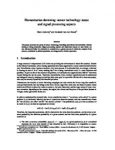
From the technical point of view, demining mobile systems .... robot. 3. Design of a Mobile Platform ..... tion θ given by the magnetic compass, the PSD camera.
Autonomous Robots 18, 275–291, 2005 c 2005 Springer Science + Business Media, Inc. Manufactured in The Netherlands. �
Multisensor Demining Robot MICHAEL YU. RACHKOV Moscow State Industrial University, ul. Avtozavodskaya 16, Moscow 109280, Russia LINO MARQUES AND AN´IBAL T. DE ALMEIDA Institute of Systems and Robotics, University of Coimbra, Polo II, 3030-290, Coimbra, Portugal
Abstract. The paper describes an advanced multisensor demining robot. The robot transport system is based on a simple structure using pneumatic drive elements. The robot has robust design and can carry demining equipment up to 100 kg over rough terrains. Due to the adaptive possibilities of pedipulators to obstacles, the robot can adjust the working position of the demining sensors while searching for mines. The detection block consists of a metal detector, an infrared detector, and a chemical explosive sensor. The robot is controlled by means of an on-board processor and by an operator remote station in an interactive mode. Experimental results of the transport, control, and detection systems of the robot are presented. Keywords: demining robot, pneumatic drive, metal detector, infrared detector, chemical explosive sensor
1.
Introduction
Landmines affect almost every aspect of life in states recovering from conflict. They maim or kill innocent civilians, obstruct emergency assistance, hamper agricultural and economic development, and prevent refugees and displaced people from returning to their homes. According to the UN, there are still more than 100 million mines in the ground in more than 60 countries (Int. Advanced Robotics Programme, 1998). The costs of mine clearance are of the same order of magnitude as the full budgets of some of the poorest mine-infested countries. The reason for this is that mine clearance still consists principally of a person with a stick, probing the ground a few centimetres at a time. It is a slow and dangerous work, and progress is measured in square metres rather than square kilometres. It costs usually 100 times more to remove a landmine than to deploy it. Automated demining technologies can be divided in mechanical demining technologies and sensor-based demining technologies. Clearing mine fields by modified tanks or trucks is a common method of mechanical
technology. It does not need sensors and is efficient on a suitable ground. Chains attached on a rotating roller hit the ground in order to explode or destroy mines. Another possibility is to mount ploughs in front of a tank which dig out the mines and moves them away, mostly without exploding. Mine ploughs are slow, in spite of being used in conjunction with rollers. A demining robot should find all mines within a given area and destroy or deactivate them. Demining principles can be divided in three main groups: mechanical destruction during detection on the spot, destruction after preliminary detection on the spot, detection, removing and destruction in a safe place. In demining, a robot must scan a mine-detecting sensor over all points in the region that might conceal a mine. To do this, the robot must traverse a carefully planned path through the target region. From the technical point of view, demining mobile systems can be subdivided as wheeled systems, caterpillar systems, legged (pedipulator) systems, screw systems, hybrid systems, and aerial systems. Examples of different types of demining robots can be found in the literature (Robotics for Humanitarian De-mining, 1998).
276
Rachkov, Marques and de Almeida
Walking robots have high adaptability to rough terrains and are suitable to overcome stones and move along sloped surfaces. A pedipulator (legged) robot can achieve stable, also active, footing. It is possible to prevent total loss of the robot in case of an unexpected explosion if the posture is such that the legs are stretched out from the center of the robot’s body like the legs of an insect or a spider. When a robot mistakenly detonates a landmine, the damage will be limited to the end of the leg, although this approach requires lightweight, inexpensive, replaceable legs. Also, by changing the broken leg, the damaged robot can be restored. The effort devoted to mobile robotic solutions would be more helpful if it were directed at simple equipment and low-cost robotic devices, which might provide some useful improvements in robustness and costeffectiveness. Standard pneumatic components can be used for designing mobile platforms to solve this task (Bach et al., 1995). Sensor based demining technologies include the following main methods: • Metal detecting is the most popular sensor method to detect mines. A metal detector consists of a coil generating a magnetic field that may be disturbed by a metal object (ATMID Mine Detecting Set, 2000). The proximity of a metal leads to induced currents and/or to a change in the magnetic field induced into another coil. Unfortunately, this method is often unreliable or time consuming, because some mines have negligible metal contents to detect and do not provide reliable discrimination within all kinds of other metallic objects on a former battlefield. • Ground penetration radar (GPR) can also be applied in mine detection. GPR devices work like radio frequency and microwave radars oriented to the soil. The measured reflected signals indicate the existence of dielectric interfaces that can be due to buried objects. This technology allows to potentially reconstruct the 3D shape and position of buried objects, but it is still quite expensive and needs dry soil, accurate scanning and a complex processing of the resulting signal in order to give good results. • Infrared sensing is a powerful technique for mine detection. Mines retain or release heat at a different rate than their surroundings, and during natural temperature variations of the environment it is possible, using infra red detectors (IR detectors) to measure the thermal contrast between the soil over a buried mine and the soil close to it (Marques et al., 2001).
Maximum burial depth of detection is estimated at 10–15 cm. The results obtained with passive infrared imagers can depend quite heavily on the environmental conditions and there are cross-over periods (in the evening and in the morning) when the thermal contrast is negligible and the mine undetectable. Active infra-red systems, which cool or heat the ground surface, can mitigate this problem, but foliage remains an additional problem. • Chemical explosive sensors can be used to detect the explosives, which slowly release vapours through evaporation. However, the relative values of the vapor pressures have important implications for the reliable detection of explosives (Gros and Bruschini, 1996), leading to the need of using very high sensitivity equipment. To compensate disadvantages of each sensor, a combination of several sensors should be used. Mines of both metal and plastic bodies can be detected by means of a combined sensor block that contains devices based on different principles. The proposed combined sensor block information provides high reliability of mine detection (Larionova et al., 2004). The developed demining robot is an attempt to make a progress in the above-mentioned directions. 2.
Robot General Structure
The mine parameters determine the type of mine sensor block to be used and some parameters of the robot, such as its scanning step (Fig. 1). The minefield characteristics influence the adjustment of the mine sensor block for a concrete kind of soil and working sensor distance. The minefield surface conditions determine the type of mobile platform. For flat surfaces it can be a wheeled platform, for a sloped surface with stones it can be a walking platform which can also be used on a flat terrain, etc. The mine sensors determine a size of the robot, its load capacity and dynamic characteristics. The dynamic characteristics of the robot and its stability depend on the parameters of the drive system. The drive control block and robot sensors define the reliability and flexibility of robot motion. The robot sensors allow implementation of feedback control of the transport and scanning motion. The drive control block is installed on board of the robot. The robot operation and mine sensor block are controlled by means of a demining robot control system. This system provides
Multisensor Demining Robot
Figure 1. Diagram of a demining robotic system structure.
a remote control from a safe distance in an automatic mode or by an operator. We consider a case of the minefield on the rough slope terrain with mines of both metal and plastic cases. The minefield can have stones of a height up to 150 mm. The angle of the slope can be up to 50 degrees. The diameter of mines is up to 200 mm. The sensor block can weigh up to 30 kg and is installed in front of the robot.
3.
Design of a Mobile Platform
The design of the demining pneumatic walking robot is intended to transport an on-board sensor block to the working zone and to scan the working zone by means of the sensor block. The transport module of the robot should have a firm and simple skeleton design to provide reliable motion with the required on-board sensor block weight along sloped surfaces. A suitable drive system for this purpose is a pneumatic system that can at the same time provide the necessary transport force and stiffness (Marques et al., 2002). The design of the transport module of the robot is shown in Fig. 2. It consists of longitudinal pneumatic cylinders and latitudinal pneumatic cylinders whose bodies are connected symmetrically and have 200 mm stroke to cover maximum mine size in one stroke. Each
277
Figure 2. Design of the transport module of the robot. 1 and 2: longitudinal pneumatic cylinders; 3 and 4: latitudinal pneumatic cylinders; 5: lifting cylinder; 6: foot; 7: metal detector; 8: IR detector; 9: chemical sensor; 10: linear position sensor of longitudinal motion; 11: linear position sensor of latitudinal motion; 12: valve units; 13: supply rotation block; 14: electronic compass; 15: on-board control computer.
pneumatic transport cylinders has two pedipulators that are fixed at ends of piston rods. The pedipulator consists of a lifting cylinder of 150 mm stroke to overcome stone obstacles of that magnitude and a foot with toothed contact surface to improve robot climbing possibilities. The detection block consists of the metal detector, the IR detector and the chemical explosive sensor. This block is connected to the front part of the robot. The linear position sensor of longitudinal motion is placed on the body of the longitudinal cylinder. The linear position sensor of latitudinal motion and the detection block is placed on the body of the latitudinal cylinder. The valve units are placed at both sides of the robot providing minimum tubing length. They are supplied from a supply rotation block connected to the main air pressure line. The rotation block allows free rotation of the robot in relation to the umbilical cord with the air supply pipe. An electronic compass is installed in the front of the platform. The on-board control computer is placed in the centre of the platform. The pneumatic cylinders can be actuated in two modes:
278
Rachkov, Marques and de Almeida
• The first mode is a transport mode. In this case the longitudinal cylinder performs motion of its pedipulators with maximum velocity by using all length of the piston rod. During this motion the robot is connected to the ground by means of the latitudinal cylinder pedipulators. They serve as support cylinders during motion in this direction. The longitudinal cylinder pedipulators are lifted. After the first step the longitudinal cylinder pedipulators must be connected to the ground and the latitudinal cylinder pedipulators must be lifted. In such a position the sensor block can be moved for one step towards the working zone, and so on. The robot can change a motion direction by 90◦ , by actuating the latitudinal cylinders as transport ones instead of the longitudinal cylinders. The rotation of the robot can be carried out by means of simultaneous motion of longitudinal (or/and latitudinal cylinders) in opposite directions during a contact of all their feet with the motion surface. • The second mode is a searching mode. During this mode the sensor block must carry out searching functions and be moved along a scanning trajectory. This trajectory is performed by means of latitudinal and longitudinal cylinders, which are actuated with a nominal searching velocity. The value of the searching velocity is determined by the characteristics of the sensor block. Field tests show that the robot can cover up to 60 m2 per hour. The covering possibilities are defined by a nominal working velocity of the demining sensors. The main specifications of the robot are shown in Table 1. 4.
Structure of the Robot Control System
The robot motion and mine sensing are controlled by means of a distributed control system. This system provides remote control from a safe distance in an automatic mode or in a teleoperated mode by an operator. The robot distributed control system architecture is shown in Fig. 3. The central computer performs the main algorithms of robot transport (navigation) motion trajectories and mine searching (covering) motion trajectories. The onboard computer fulfils the control of the transport robot drive system. It transmits all data from sensors to the central computer. The on-board computer is controlled by means of a central computer that is placed out-
Table 1.
Main specifications of the robot.
Position 1
Specification Overall dimensions – length
750 mm
– width
750 mm
– height 2
Description
280 mm
Weight (without equipment)
48 kg
3
Payload
up to 70 kg
4
Number of pedipulators
8
5
Pedipulator design
Adaptive to motion surface shape
6
Degrees of freedom
12
7
Transport speed
up to 2.5 m/min
8
Searching speed
from 0.5 m/ min
9
Sensor block
metal detector IR detector with heating unit chemical sensor
10
Control system
on-board processor, PC controller
12
Maximum height of obstacles
150 mm
13
Inclination of the motion surface
up to 50 degrees
14
Supply – air pressure
6 bar
– DC voltage
24 V
– size of the supply unit
600 mm × 500 mm × 250 mm
side of a zone of danger. The central computer analyses the motion and sensor information. An operator can change the mode of motion according to the situation. A triangulation-based localization system measures the robot position in relation to external references. This information serves for flexible navigation of the robot. A sonar sensing unit is used for obstacle avoidance and robot navigation. Obstacles in the robot surroundings are detected by a ring of 16 ultrasonic transducers oriented at equally angular distances around the platform (Fig. 4). The distance is obtained by measuring the time-offlight (TOF) of the ultrasonic wave: initially the transducer works as a transmitter, emitting a train of energy pulses, and then changes to the receiver mode to detect the echo reflected by the target object. The transducers
Multisensor Demining Robot
Figure 3. Structure of the robot distributed control system.
Figure 4. Ultrasonic ring. 1: robot, 2: ultrasonic transducer, 3: measured range.
1% of the range. The interfacing and signal processing with groups of up to four transducers is done by means of Microchip PIC based intelligent boards (Moita and Nunes, 2001). The transport drive system of the robot (Fig. 5) consists of an on-board computer, which is connected to a central computer and, by means of an interface, to two valves V1 of the longitudinal cylinders (LNC), to two valves V2 of the latitudinal cylinders (LTC), to four valves V3 of the longitudinal lifting cylinders (LLN) and to four valves V4 of the latitudinal lifting cylinders (LLT). All 5/3-way valves have a closed neutral position and two flow positions. The flow positions provide motion of the piston rod in opposite directions. The closed neutral position is a “Stop” position with both chambers pressured, which locks a piston rod of a cylinder in a desirable point. The robot can cover a minefield without obstacles using only linear motion. The transport and scanning trajectories of the robot along a minefield with obstacles demands to use rotation of the robot in order to orientate it to move around obstacles. It is possible to perform four different kinds of robot rotations. All of them are based on a frictional principle. A supported rotation is carried out by means of motion of the feet of one of the transport cylinders in relation to the parallel cylinders fixed feet. An algorithm of the rotation is presented in Table 2. This mode is intended for small corrections in motion direction. An accelerated rotation is fulfilled by means of the pedipulator motion of both parallel transport cylinders in opposite directions, at the same time. This mode permits to perform relatively rapid rotation of the robot body. A centered rotation is performed by means of the perpendicular pair of pedipulators around a pedipulator support. It allows changing an angle direction more
Table 2.
Algorithm of the supported rotation.
Rotation direction
employed are Polaroid 600 series instrument grade transducers. These transducers are composed by a circular piston with 19 mm radius that periodically emits short ultrasonic bursts of 49.4 kHz frequency. These sensors can measure distances to target surfaces that range from 30 cm till about 10 m inside a cone with 25 degrees aperture. The typical absolute accuracy is
279
Clockwise
Valve and cylinder positions V31 , V32 V33 , V34 - left (LLN piston-rod - down) V41 ,V42 , V43 , V44 - right (LLT piston-rod - up) V11 – right (LNC1 piston-rod - forward)
Counterclockwise
V31 , V32 V33 , V34 - left (LLN piston-rod - down) V41 ,V42 , V43 , V44 - right (LLT piston-rod - up) V12 – right (LNC2 piston-rod - forward)
280
Figure 5.
Rachkov, Marques and de Almeida
Transport drive system of the robot.
precisely in relation to the determined center of rotation. A safe rotation can be carried out by means of the support of all pedipulators in the low position. Such a position of the pedipulators allows providing a safe range of pedipulator lateral forces during rotation for all types of motion surfaces because the piston rod lever effect is minimal. All the previously mentioned rotation modes are illustrated in Fig. 6. The searching mode is carried out along scanning trajectories, which are combined of latitudinal and longitudinal motions. The averaged characteristics for the supported rotation on different surfaces are shown in Fig. 7. The value of the rotation angle for one stroke has a standard deviation of about 5% for different strokes but averaged characteristics for all kinds of surfaces are linear. The angle value is proportional to the friction coefficient between the pedipulators and the motion surface. For example, the robot can be rotated through 45◦ on the soft ground and sand in four strokes. The averaged characteristics for the accelerated rotation are shown in Fig. 8. The accelerated rotation is more effective from the viewpoint of rotation speed, but this mode has a stroke angle standard deviation of about 7%. The robot can be rotated by 90◦ on the ground with vegetation in just three strokes. It is necessary to notice that sometimes the rotation on the ground with vegetation cannot be completed
because of pedipulator wedging. In such cases, the safe rotation mode is preferable. The rotation characteristics of the safe rotation mode are about the same as the supported rotation characteristics. Transport and scanning trajectories of the robot over a minefield without obstacles, or with obstacles that can be overcome by moving up the pedipulators as shown in Fig. 9. The shown trajectory of the robot allows scanning all the surface of the minefield without rotation motion, for situations with no essential deviations from the set trajectory. If it is necessary to correct a trajectory, one of the rotation modes can be used. The number of robot rotations depends on the scanning program. It is possible, for example to perform two rotations or one rotation to cover one obstacle that cannot be overcome by pedipulators, as shown in the scanning diagrams in Figs. 10 and 11. The minefield and obstacles can have any configuration. The robot allows scanning in different trajectories with the step from 1 cm to 20 cm according to the real configuration of the minefield and obstacles to search their perimeters with corresponding accuracy. Feedback control is used for positioning the pedipulators in order to overcome obstacles that are smaller than the pedipulators stroke while moving along a rough terrain. A diagram of the control of the pedipulators positioning is shown in Fig. 12. The lifting cylinder actuates the piston rod connected to the foot towards the ground. The contact of the
Multisensor Demining Robot
Figure 6. Rotation modes. direction of the platform
pedipulator contacted to the ground,
Figure 7. Experimental characteristics for the supported rotation. 1: hard ground and stone, 2: soft ground and sand, 3: ground with vegetation.
lifted pedipulator, → motion direction of the pedipulator,
281
rotation
Figure 8. Experimental characteristics for the accelerated rotation. 1: hard ground and stone, 2: soft ground and sand, 3: ground with vegetation.
282
Rachkov, Marques and de Almeida
Figure 11. One rotation scanning. Figure 9.
Transport and scanning trajectories of the robot.
Figure 12. Control of the pedipulators positioning. 1: lifting cylinder, 2: piston rod, 3: foot, 4: footplate, 5: position sensor, 6: valve, 7: platform, 8: obstacle.
Figure 10.
Two rotations scanning.
footplate with the ground is sensed by a polymer-based force sensing resistor (FSR from Interlink Inc. USA) sandwiched in-between the foot and the footplate. The sensed signal allows to control each lifting cylinder valve to block the piston rod in a desired level. As result, all feet can have different levels according to surface roughness to keep platform on the same nominal level independent on height of obstacles. To increase climbing possibilities of the robot, metal teeth can be mounted on the footplate, if necessary. The demining robot control system is based on a modular distributed architecture with high-level mod-
ules running on a remote PC with RT-Linux and lowlevel control modules running on an on-board microcontroller with µC/OS-II real-time operating system (Fig. 13). The modules running in the remote PC include remote control through a joystick, a user interface that monitors the robot state, allows prior map introduction and task establishing, and modules for automatic terrain mapping, path planning and trajectory generation. The lower-level modules run on a Motorola 68HC912DG128 microcontroller. The main modules found in this level are the communication management and command interpreter module, signal acquisition and pre-processing from demining sensors, as well as localization and trajectory control modules.
Multisensor Demining Robot
283
A pneumatic tube for compressed air supply and an electrical cable (RS485, 115.2 kbps and 24 V DC power supply) for power supply and data communication compose the umbilical cord, with a length up to 100 meters. The robot control board is based on a Motorola 68HC912DG128 microcontroller unit (MCU). This microcontroller provides 128 kB Flash memory, 2 kB EEPROM and 8 kB SDRAM memory on chip. The chip provides also an extensive range of peripherals, like a 16 channel 10 bits analog-to-digital converter (ADC), four-channel pulse width modulator (PWM), several types of serial communication units (SCI, SPI, I2 C, CAN) and an enhanced capture timer unit (ECT). 5.
Figure 13. Hierarchical architecture of the control system.
Figure 14 represents the hardware architecture of the robot. The main modules are the controller connected through an umbilical cord to the remote control system, pneumatic cylinders with the respective electro-valves, motion sensors, and localization sensors.
Figure 14. Robot on-board hardware architecture.
Sensors for Motion Control
Each transport cylinder of the robot has two kind of sensing devices: two end-of-stroke detectors and an optical triangulation sensor with analog output. The end-of-stroke detectors are used for normal motion. The optical sensor, Sharp GP2D12, is used to measure the cylinder position during sub-stroke actuation. This actuation mode is useful for fine scanning of suspicious areas. The sensors are installed on the robot as it is shown in Fig. 15. The optical sensors are mounted both on the longitude and on the latitude cylinders. A reflective screen
284
Rachkov, Marques and de Almeida
Figure 15. Linear position sensor of the motion cylinders. 1: cylinder, 2: piston rod, 3: pedipulator, 4: optical sensor, 5: reflective screen.
Figure 17. Representation of localization by means of optical triangulation.
Figure 16. Experimental characteristic of the position sensor.
is placed on the pedipulator at the end of the piston rod. The main characteristics of the optical sensors are a measuring range L from 10 to 80 cm with a nonlinear output from 3.1 to 0.6 V. In the present set-up, the working distance was chosen from 15 to 35 cm. After amplification, the sensor output is made linear by the local controller through a calibration lookup table. An experimental characteristic of the position sensor is presented in Fig. 16. An initial position of sensor from the origin was chosen equal to 15 cm to have a more linear working zone of the sensor output signal in the range of the cylinder stroke (20 cm). Some non-linearity of the sensor characteristics are compensated by software. The robot localization and orientation (x, y, z, θ, γ ) is performed integrating the performed motion of the transport cylinders and by means of global sensing with a global triangulation system, an electronic compass, and inertial sensors. Robot rotation angle is measured by means of the electronic compass. This compass, based on a two-axis
Honeywell magnetoresistive bridge, provides orientation information with an accuracy of 0.5 degrees. The platform inclination is measured by two two-axis Analog Devices accelerometers when the platform is still. The triangulation system uses a two-axis Position Sensitive Detector (PSD) camera to measure the angles to two or more optical beacons placed in known positions. The PSD is an area photodetector that allows measuring the incident position of an optical beam in its surface. Figure 17 shows the measuring principle in a 2D situation, considering the utilization of a one-axis camera and two optical beacons placed in known positions. If the system knows the position (x1 , y1 ) and (x2 , y2 ) of the two optical beacons and the absolute orientation θ given by the magnetic compass, the PSD camera optical centre (x0 , y0 ) can be determined by the interception between the two rays that connect the beacons with the centre of the lens. In order to eliminate the noisy effects coming from the background light, the PSD-based camera uses a narrowband optical filter and the active beacons are modulated at a frequency of 5 kHz and sequentially switched. The PSD-based camera uses a UDT SC10D PSD with a 16mm focal length lens. With this arrangement the camera have a field of view of about ±20◦ and after calibration, it was possible to measure angles with better than 0.02◦ accuracy. 6.
Mine Detection Block
The mine detection block consists of a metal detector, an infrared detector, and a chemical explosive sensor.
Multisensor Demining Robot
285
Figure 19. Mine of MAPS type on the surface of the test field. Figure 18. Position of the metal detector on the robot. 1: metal detector, 2: robot platform, 3: support, 4: height adjusting unit, 5: pedipulator, 6: mine, 7: metal part of the mine, 8: transmit field, 9: receive field.
The metal detector is based on the effect produced by metallic objects in variable electromagnetic fields. The transmitting coil, embedded in the search head of the metal detector, generates such a field. As the search head is swept over the ground, the receiving coil in the search head detects the very small variations in the electromagnetic field caused by metallic objects. The variations are then processed to generate a signal indicating the presence of metal in the ground beneath the search head. The metal detector is installed on the front part of the robot as it is shown in Fig. 18. The functional principle of VLF (Very Low Frequency) Transmitter and Receiver metal detector is as follows. Inside the metal detector’s search head, there is a coil called the transmit coil. A current is driven through the coil to create an electromagnetic field. The direction of the current flow is reversed several thousand times every second. When the current flows in a given direction, a magnetic field is produced whose polarity points into the ground. When the current flow is reversed, the field’s polarity points out of the ground. Any metallic or other electrically conductive object, which happens to be nearby, will have a flow of current induced inside of it by the influence of the changing magnetic field. This current flow inside a metal object in turn produces its own magnetic field, with a polarity that tends to be pointed opposite to the transmit field. A second coil of wire inside the loop, the receive coil, is arranged so that nearly all of the current that would
ordinarily flow in it due to the influence of the transmitted field is cancelled out. Therefore, the field produced by the currents flowing in the nearby metal object will cause currents to flow in the receiver coil which may be amplified and processed by the metal detector’s electronics without being swamped by currents resulting from the much stronger transmitted field. Metal detectors can distinguish metal objects from each other based on the ratio of their inductance to their resistivity. This ratio gives rise to a predictable delay in the receiver signal at a given frequency. An electronic circuit called a phase demodulator can measure this delay. The metal detector ATMID was used with the robot (ATMID Mine Detecting Set, 2000). The detector was tested to detect a real mine but without explosives. It was Portuguese mine of MAPS type with plastic case of 85 mm diameter that contains a 1 g metal part (Portuguese Corporation of Explosives, 2001). A picture of the mine is shown in Fig. 19. The influence of the ground type on the mine detection was researched for different types of ground, such as sand, soil and stones, with a variable mine depth up to 10 cm. The field results were obtained in the searching mode of the robot for three levels of mine positions in sand— on the surface, at 5 cm depth, and 10 cm depth. The scanning step is 200 mm—the distance from the initial point of motion to the end of the drive stroke. The detector output signal is frequency. The results are shown in Fig. 20. Maximum output signal was reached for the mine position on the surface and that it becomes smaller as the depth increases. The mine was detected with 20 mm
286
Rachkov, Marques and de Almeida
Figure 20. Mine detection at three depth levels in sand.
Figure 21. Influence of the ground type on the mine detection signal.
accuracy and maximum signal is just above the center of the metal part of the mine. Figure 21 shows the influence of the ground type on the mine detection signal for sand, soil and stones at the mine depth of 10 cm. Sand allows receiving the strongest signal from the mine. Stones reduce the output signal about 5% and the compact soil leads to a reduction of about 2%.
The field test was done to compare different environmental conditions in the sense of the ground humidity for the mine detection (Fig. 22). The dry soil has slightly better response than the wet one. The difference of the output signal amplitude is about 3%. It can be concluded that humidity does not influence dramatically on the mine detection results, when a metal detector is used.
Multisensor Demining Robot
287
Figure 22. Influence of humidity on the mine detection.
Figure 23. Testing setup of an active Infrared mine detection system prototype. The system is composed by a microwave emitter and two infrared detectors.
The detection of landmines with the IR sensing system is based on the scanning of a suspicious area with a microwave emitting valve and a temperaturemeasuring device. The proposed IR system is based on the differences between dielectric properties of landmines and the soil. In this sense the technique is general, since the dielectric characteristics of plastic landmines and common soil are always different. Therefore, this technique works outdoors under a wide variety of environmental conditions, but the system will perform
better with humid soil, in which case it will be possible to detect significant temperature gradients above the landmine. The implemented prototype consists of a microwave klystron coupled to a horn antenna and two infrared detectors (see Fig. 23). The two infrared detectors operate in different wavelengths allowing the compensation of the temperature measurement in soils with different radiation parameters. The system is coupled to the demining mobile platform. The heating module controls the microwave klystron. The acquisition module builds a temperature image fusing the output of the two infrared detectors with position information. The processing module identifies possible landmine signatures in the temperature image comparing features of the image with a previously stored database of landmine signatures. The specifications of the two applied infrared sensors are shown in Table 3.
Table 3.
Specifications of the applied infrared sensors.
Model Temperature range Field-of-view Wavelength Response time
OS65-J-R2-4
OS36-10-K-80F
57–145◦ C
10–49◦ C
24:1
10:1
8–14 µm
6.5–14 µm
300 ms
80 ms
288
Rachkov, Marques and de Almeida
Figure 24. Heat distribution after the first phase.
The response time of the IR system can be a critical parameter for a scanning device. If the scanning velocity is too high, the IR sensors cannot follow the temperature gradients in the soil. Concerning this aspect, the used IR sensors present no limitation, because the velocity of the platform is more than 10 times slower than the dynamics of the IR sensors (about 4 s per stroke vs. 0.3 s full range response time). The signal conditioning for OS65-J-R2-4 sensor allows the choosing of several sensor parameters, like
Figure 25. Heat distribution at the end of the second phase.
temperature range, field-of view (3:1, 7:1, 15:1, 24:1) and output type (thermocouple J or K, 1 mV/◦ C, 4–20 mA, 0–20 mA and 0–5 V). The output from each IR sensor is gathered with an Advantech PCL818 12 bit resolution data acquisition card. In order to evaluate the effectiveness of the proposed prototype in real conditions, a finite element model was developed and the system was simulated for different environmental conditions and operating conditions. Figures 24 and 25 show the results obtained after
Multisensor Demining Robot
heating a simulated minefield. These Figures represent the cut of a volume of soil (sand with 15% humidity) with a plastic landmine in the interior. The simulation is composed by two phases. In the first phase, all the materials were considered at an initial temperature of 290◦ K and the workspace was exposed to homogeneous electromagnetic radiation of 2.45 GHz, 1 kW spread over an area of 0.1225 m2 . The temperature raises according to the materials properties and after t1 attained the distribution represented in Fig. 24. The initial values of the second phase are the final values of the first phase. In this phase the material is not exposed to radiation. Therefore, only diffusion phenomena’s occur by heat conduction. As can be seen in Fig. 25, the surface over the landmine is colder then the neighborhood because the quantity of heat accumulated over the landmine was smaller than in the other regions, so it cooled faster. Chemical explosive sensors allows the detection of the mine explosive materials, which slowly release vapors leaking from the mine cases. The high-vaporpressure explosives are relatively easy to detect from their vapor emissions using detectors such as ion mobility spectrometers. When molecules of nitroaromatics bind to the polymers, the intensity of the fluorescence is greatly reduced due to the amplifying effect of the polymer. This reduction is proportional to the mass of the quencher adsorbed by the films and is measured by the sensor system (Fisher, 2001). A schematic diagram of the sensor is shown in Fig. 26. A blue light emitting diode (LED) serves as the fluorescence excitation source. Light from the LED passes through a lens that focuses the beam and directs it onto an interference filter allowing the transmission of a 370 nm narrowband light beam. The filtered light then passes at nor-
Figure 26. Schematic diagram of the chemical sensor.
Table 4.
289
Specifications of the chemical sensor.
Parameter
Value
Sensitivity
10−13 g/cm3
Response time Maximum working distance
1s 160 mm
Weight
2 kg
Length
200 mm
mal incidence through two borosilicate glass substrates coated with thin films of the polymer. The glass substrates act as planar waveguides for light emitted by the polymer and define the sensor chamber. A significant fraction of the fluorescence couples into the substrates and is waveguided to the edges of the substrates. Additional light is reflected back into the waveguide paths by reflective coatings on three edges of the substrate. Emitted light is detected by a small photomultiplier tube (PMT) or by an avalanche photodiode. The current works integrating and using olfaction in mobile robots to find odor sources use inexpensive metal oxide gas sensor-based systems and dummy gas sources emitting common gases, like ethanol (Marques et al., 2002, 2003). But there are commercial and compact chemical sensing systems suitable for demining (ARLI Spetstechnika, 2001). An example of such system is presented in Fig. 27. This system has the main technical parameters according to Table 4. It should be taken into account that the chemical compounds of military grade explosives used in land mines degrade in the soils in which they are buried, leading to a change in their vapor signature (Miyares and Jenkins, 2000). The application of the described sensors improves the mine detection performance, since there is more available information, reducing false alarms and the inaccuracy of the mine
Figure 27. Portable chemical sensor.
290
Rachkov, Marques and de Almeida
level tasks and design of a demining manipulator for extraction, isolating or marking of mines.
Acknowledgments This work was partially supported by the Portuguese Science and Technology Foundation (FCT/MCT) by project DEMINE, contract POSI/36498/SRI/2000.
References Figure 28. Multisensor demining robot on a test field.
position estimation. The data fusion calculation algorithm that can be applied for this task is given in Larionova et al. (2004). The developed demining robot with multisensor detection block is presented in Fig. 28 on a test field searching a mine. Due to the adaptive possibilities of the pedipulators to obstacles (stones in the picture), the robot can keep the working position of the demining sensors while searching for mines. 7.
Conclusions
An advanced multisensor demining robot was developed. It has improved payload possibilities due to the robust design and pneumatic drive system. The robot can transport demining equipment up to 100 kg across rough and sloped terrains. Robot pedipulators are adaptive to obstacles and terrain unevenness, so it can keep the working position of the mine detection block while searching for mines. The robot mine detection block consists of a metal detector, an active infrared detection system, and a chemical sensor. Data fusion from the sensors allows reducing false alarms and improves reliability and accuracy of demining operations. The robot is controlled by means of an on-board processor and by an operator remote station in an interactive mode. Experimental results of the transport, control, and detection systems show effectiveness of their functioning. Due to the relatively low cost design, the robot application can potentially reduce demining expenses. Future developments will include increasing the robot autonomy by transferring to the robot some high-
ATMID Mine Detecting Set. 2000. Operating Manual. Schiebel Elektronische Geraete GmbH, Vienna, Austria. ARLI Spetstechnika. 2001. Explosives detection equipment. Catalogue. Moscow, Russia. Bach, Fr.-W., Rachkov, M., Seevers, J., and Hahn, M. 1995. High tractive power wall-climbing robot. Automation in Construction, 4(3):213–224 (Elsevier Science). Fisher, M. 2001. Detection of Trace Concentrations of Vapor Phase Nitroaromatic Explosives by Fluorescence Quenching of Novel Polymer Materials, Colin Cumming Nomadics, Inc., 1024 S. Innovation Way, Stillwater, OK 74074, USA. Gros, B. and Bruschini C. 1996. Sensor technologies for the detection of AP mines: a survey of current research and system developments. In Int. Symposium on Measurement and Control in Robotics, Brussels, Belgium. Int. Advanced Robotics Programme. 1998. 1st Int. Workshop on Robotics for Humanitarian Demining, Laas-Cnrs, Tolouse, France. Larionova, S., Marques, L., and de Almeida, A.T. 2004. Toward practical implementation of sensor fusion for a demining robot. In Proc. IEEE/RSJ International Conference on Intelligent Robots and Systems (IROS), Sendai, Japan. Marques, L., Almeida, N., and de Almeida, A.T. 2003. Olfactory Sensory System for Odour-Plume Tracking and Localization. In Proc. IEEE Int. Conf. on Sensors, Toronto, Canada. Marques, L., Nunes, U., and de Almeida, A.T. 2002. Olfaction-based mobile robot navigation. Thin Solid Films, 418(1):51–58 (Elsevier). Marques, L., Rachkov, M., and de Almeida., A.T. 2001. Detection and localization of antipersonal mines by means of mobile robots. Robotica, Publindustria, (43):9–13 (in Portuguese). Marques, L., Rachkov, M., and de Almeida, A. 2002. Mobile pneumatic robot for demining. In Proc. Int. Conf. on Robotics and Automation, Washington, USA, pp. 3508–3513. Miyares P. and Jenkins T.F. 2000. Estimating the Half-Lives of Key Components of the Chemical Vapor Signature of Land Mines, US Army Corps of Engineers. Moita, F. and Nunes, U. 2001. Multi-echo technique for feature detection and identification using simple sonar configurations. In IEEE/ASME Int. Conf. On Advanced Intelligent Mechatronics AIM ’01, 389–394, 8–12 July, Como, Italy Portuguese Corporation of Explosives (SPEL). 2001. Landmine Monitor Report. Lisbon, Portugal. Robotics for Humanitarian De-mining. 1998. In Workshop WS9, IEEE ICRA Conference, Leuven, Belgium.
Multisensor Demining Robot
291
ing and MsC. degrees in Electrical Engineering from the Faculty of Science and Technology of this University in 1992 and 1997 respectively. He is currently working toward the Ph.D. degree and teaching in the Electrical and Computer Engineering Department. His current research interests include sensors, mechatronics, mobile robotics and industrial automation.
Michael Yu. Rachkov is Professor of Automation at the Moscow State Industrial University. He graduated in Automatic Control Systems from Moscow Higher Technical School, 1979. He held academic posts at the Institute for Problems in Mechanics, Russian Academy of Sciences. In 1986 he completed his PhD in industrial robotics and received his DSc in mobile robotics in 1997. Professor Rachkov has been leading in several international projects like EUREKA and REMAPHOS. He has published over 170 papers and several books in the field of automation, robotics and optimal control. He is a member of Russian Cosmonautics Academy and International Informatization Academy.
Lino Marques is a research engineer at the Institute of Systems and Robotics of the University of Coimbra. He received the Engineer-
An´ıbal T. De Almeida graduated in Electrical Engineering, University of Porto, 1972, and received a Ph.D. in Electrical Engineering, from Imperial College, University of London, 1977. Currently he is a Professor in the Department of Electrical Engineering, University of Coimbra, and he is the Director of the Institute of Systems and Robotics since 1993. Professor De Almeida is a consultant of the European Commission Framework Programmes. He is the co-author of five books and more than one hundred papers in international journals, meetings and conferences. He has coordinated several European and national research projects.