17th European Signal Processing Conference (EUSIPCO 2009)
Glasgow, Scotland, August 24-28, 2009
MULTIVARIABLE STATISTICAL CLASSIFICATION OF 3D BONE MICROARCHITECTURE USING MORPHOLOGICAL AND MECHANICAL FEATURES Rachid JENNANE1 , Gabriel AUFORT1 , Hugo LHERITIER2 , Claude Laurent BENHAMOU3 1
Institut PRISME, UPRES EA 4229, Université d’Orléans, France Laboratoire MAPMO, UMR CNRS 6628, Université d’Orléans, France 3 Equipe Inserm U658, Centre Hospitalier Régional d’Orléans, France phone: +33 2 38 49 45 38, fax: +33 2 38 41 72 45, email:
[email protected] web: www.univ-orleans.fr/prisme 2
ABSTRACT Evaluating trabecular bone microarchitecture is not possible in the clinical routine nowadays. Based on simplified skeleton and Finite Element models, we have developed different image processing and simulation techniques to investigate bone microarchitecture and its mechanical stiffness. This work defines improved models for 3D bone architecture that generates multiple features. These parameters can be combined in a statistical discriminant analysis in order to study bone diseases such as osteoporosis. A clinical study is led on 2 populations of arthritic and osteoporotic bone samples. The results show the ability of our improved techniques to discriminate the 2 populations. 1. INTRODUCTION Bone Mineral Density (BMD) is one of the most important and best studied factors conditioning bone strength and osteoporotic fractures [17]. But screening osteoporosis and other bone related alterations using BMD is not sufficient since it does not cover the entire diagnosis. Other factors like bone microarchitecture, bone macroarchitecture, cortical thickness or bone quality play a role [13]. Authors have shown that associating microstructural information with BMD would allow rising the diagnosis up to 90 % characterization of bone’s stiffness [8]. Features such as Trabecular Thickness (Tb.Th) or Trabecular Spacing (Tb.Sp) are starting to become famous in microarchitecture characterization, as they complete the diagnosis of the physician. However, their efficiency is limited by geometrical models assumptions. In fact, large scale porous media are often composed of a complex mix of different shapes. In the case of trabecular bone, it is clearly established that the structure is composed of rod and plate items. We have developed and validated a series of 3D tools for measuring morphological properties of disordered porous media such as trabecular bone, sponges, sand and soils [2, 3, 4]. A new skeleton-based technique called Hybrid Skeleton Graph Analysis (HSGA) [2] is used to create structural models that take into account the shape of the object, in order to get a precise local geometry description. The method is based on homotopic curve and surface thinning which preserves the topology of the medium. For this purpose, simplified skeleton-based models have been investigated to retrieve morphological information from large-scale disordered porous media. The concept has been pushed forward with the integration of shape information directly into the
© EURASIP, 2009
models. The HSGA is born from this need to improve the quality of skeleton geometrical properties. Finally, we improved a previously published beam Finite Element (FE) analysis [15]. A full protocol [6] has been developed for evaluating stiffness of large-scale porous media based on the HSGA. Using advantage of both beam elements for rod shaped structural items and shell elements for plate shaped items, the HSGA enables a fast and precise mechanical simulation. The study presented in this paper is a discriminant statistical analysis using the HSGA technique and its associated mechanical FE models led on 2 populations composed of arthritic and osteoporotic trabecular bone samples. It emphasizes the improvements induced by the new beamshell model and the ability of its features to discriminate the arthritic and osteoporotic populations. The paper is organized as follows: first, we recall the previous work on the HSGA technique. Then, the conversion of the HSGA model into FE elements is exposed. Finally, the results from the statistical analysis are reported and discussed. 2. HYBRID SKELETON GRAPH ANALYSIS Characterizing the morphology and topology of disordered porous media has first been led using global methods based on physical models that cannot give precise information about the medium’s structure and its local properties. In 2000 a new method called Line Skeleton Graph Analysis (LSGA) [14] was introduced for studying porous media at local stage. However, using a curve skeleton, the LSGA has also its drawbacks since all non-cylindrical shapes are better described by 2D-surfaces rather than 1D-curves. 2.1 Hybrid skeleton The HSGA [2] relies on a new hybrid skeletonization process [3] which is computed by processing curve or surface thinning, depending on the local shape of the object. To switch between the 2 skeleton variants, we improved a recent algorithm which classifies the voxels of an object according to their topological predisposition to belong to a plate or to a rod zone [4]. First, surface thinning is applied; then curve thinning, except on plate zones. This technique creates a new kind of skeleton called hybrid skeleton which is composed of 2D-surfaces and 1D-curves. Figure 1 compares the hybrid skeleton of a trabecular bone sample with its equivalent curve
1557
(a)
(b)
(a)
(a)
(c)
(d)
(b)
(b)
(c)
(c)
(d)
(d)
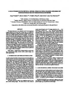
Figure 1: A trabecular bone sample (a), its curve skeleton (b), surface skeleton (c) and hybrid skeleton stacked over the original object (d)
and surface skeletons. The hybrid skeleton (Figure 1.d) models the plate zones by 2D-surfaces, which prevent the generation of parasite paths as can be seen on the curve skeleton (Figure 1.b). These imperfections are due to the curve skeletons sensitivity to the object surface irregularities. The hybrid skeleton also models rod zones by 1D-curves, on the contrary to the surface skeleton which does not erode rods enough (Figure 1.c). Furthermore, the hybrid thinning algorithm preserves connectivity which is an essential feature when characterizing porous media. 2.2 Classification Once the hybrid skeleton has been computed, a classification step is applied to label each voxel of the skeleton according to its structural role. As in [14], 2 voxels of the solid phase are neighbors if they are 26-connex (i.e. they share at least one corner). Complementary, voxels of the pore phase are neighbors if they are 6-connex (i.e. they share at least a face). Two classes of voxels have been defined: "rods" and "plates". The classisfication step is illustrated on Figure 2.c.
Figure 2: Illustration of the HSGA model and its different computing steps on a test vector composed of 2 plates and 9 intersecting rods and a trabecular bone sample. Original object (a), Hybrid skeleton stacked over the original object (b), Classified hybrid skeleton stacked over the original object (c) and final HSGA segmented model (d).
2.3 Individualization
2.4 Segmentation
After classification, the role of each voxel in the skeleton can be determined. However, the rods and plates of the structure cannot be processed one by one, since they have not been extracted and individualized. To do so, all the information associated to one plate or rod must be gathered. This is the object of the final step of the HSGA. The individualization algorithm of each element of the structure is a 3-step loop which consists in finding a solid phase element algorithm, spreading the information until the element boundaries are found and registering the new element in the model. These 3 steps are repeated until no element is found. The skeleton’s nodal information (i.e."node" and "line-end" voxels) is kept and associated to each element of the model as an "interface" data. We know exactly which elements are connected to each node, and which nodes interface each element.
The HSGA is completed by processing a 3D region-growth segmentation of the original object based on the classified skeleton. It takes the skeleton voxels of each element as a seed and iteratively merges neighbors from the original volume. As a result, each solid voxel of the object is finally associated to an element of the HSGA model (plate or rod) (Figure 2.d). The HSGA contains morphological, topological and volumetric information. This enables several properties to be measured: volume, section and thickness of each element, global features such as rod/plate proportion, or anisotropy, ... In this paper, we used the HSGA as a basis for the generation of Finite Element (FE) models.
1558
(a) (a)
(b)
(c)
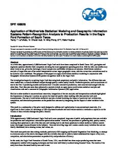
Figure 3: Illustration of the rods to beam elements chains conversion: voxels of the 1D path extracted from its curve skeleton with intermediate nodes (a), simple cylinder model assumption (b), and beam chain modeling of the item using local thicknesses map (c)
(b)
Figure 4: Illustration of the plates to shell elements conversion: 26-connex voxels of the 2D surface extracted from its surface skeleton (a), and example of a shell elements triangulation using Surface Marching Cubes (b)
3. MECHANICAL ASSESSMENT OF POROUS MEDIA The reference for Finite Elements (FE) analysis of discrete samples is unquestionably the voxel-to-element conversion as evoked in [18]. But in the case of skeleton-based models, other type of elements can be used to simplify largescale problems and gain computing time and resources. The HSGA can be used in this way as a basis for the generation of simplified FE models. This section explains our modeling choices and describes the protocol used to convert data from the HSGA to FE for both rods and plates items. First, the method used to convert rod shapes to beam chains is explained. Then the triangulation technique used to convert plate shapes to shell elements is described. 3.1 Rods to beam elements chains conversion The FE that matches the geometry of a straight rod is the beam element. It is described as a 1D segment, which is assigned a circular cross section. This technique has first been investigated by [15, 19] to assess the stiffness of trabecular bone. However, results have shown that modeling bone by a simple rod network is not sufficient to get a precise stiffness evaluation, due to geometrical lack of accuracy. In order to convert a rod item to FE, we introduced the "beam chains" concept [5]. Inspired from a feature extraction technique used in the field of 3D animation [16], the beam chain introduces evenly set intermediate nodes on the curve skeleton. A process called "splitting" breaks the curve into small segments that better match the curvature of the rod item as can be seen in Figure 3. Each beam element is then assigned a local section computed using the thickness map of the object [9]. 3.2 Plates to shell elements conversion Plate zones are badly described in the case of beam-only models [15, 5], which lead to a non-negligible bias for morphological results. It is suspected that this lack of geometrical accuracy also alters mechanical results. No work has really been done on modeling plates. Recently, Lenthe et al. [19] had the idea of converting a plate into a set of beams instead of a single beam. Yet, the efficiency of this conversion can be discussed. We introduced an original approach that gather the power of a new triangulation method and a better choice of FE type to improve plate modeling [6]. The FE used to describe planar shapes is the shell element. It
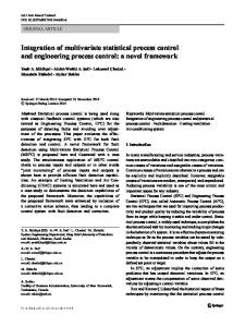
OA
OP
Figure 5: Two 643 voxels sample extracts from the 2 populations that illustrate the microarchitectural differences in coxarthric (OA) and osteoporotic (OP) trabecular bones. is defined as a 2D medial surface geometry (either triangle or quad strips for example) which is assigned a thickness value. One of our algorithms called Surface Marching Cubes (SMC) [1] computes the full-resolution triangulation of the 26-connected surface. The process is inspired from a famous spatial sampling method, Marching Cubes (MC) [12] which subdivides space into cells and search those that intersect the implicit surface. Each generated triangle is converted into a shell element, then assigned a section according to the local thickness map value. Figure 4 presents the result of the triangulation of a simple 26-connex surface set. 4. CLINICAL STUDY In addition to the validation by the test vectors and in order to compare the efficiency of the different proposed techniques, we relied on medical bone data with an a priori knowledge of fracture risk. Two populations of each 9 samples extracted from post-mortem femoral head and acquired using a SkyScan micro-scanner were studied. The first 9 OP samples have been extracted from osteoporotic patients with known bone fracture risk. The other 9 OA came from coxarthric patients, which bone structure is known to be hypertrophied. Figure 5 shows 2 extracts from an OA and an OP sample. The differences between these two bones are obvious: high density and connectivity for the OA sample and thinning and rupture of the trabeculae for the OP one. After slides reconstruction, the discrete samples were pre-processed to 2003 isotropic voxels cubes, with a resolution of 24.04 µ m per voxel side (i.e. 4.568 mm3 for each sample). Each technique has been processed on each of the 18 bone samples using both LSGA and HSGA models with and without mechanical features: a beam-only model using the approach developed in [15], then a beam/shell model us-
1559
ing the improved technique described in this paper. The split property has been turned on and off for rod modeling. Besides, the well-established Mean Intercept Length technique (MIL) [20] has been run for cross-comparison purposes. The following features have been extracted: Bone Mineral Density (BMD, defined as Bone Volume over Total Volume, BV/TV), Bone Surface over Total Volume (BS/TV), Bone Surface over Bone Volume (BS/BV), Trabecular Number (Tb.N), Trabecular Spacing (Tb.Sp), Trabecular Thickness (Tb.Th), connectivity (β 1), number of cavities of the solid phase (β 2). New Mean features have also been extracted: Rod Length (Ro.L), Rod Section (Ro.S), Rod volume (Ro.V), Rod Thickness (Ro.Th), Rod Number (Ro.N), Rod percentage (Ro.%), Plate Surface (Pl.S), Plate Volume (Pl.V), Plate Thickness (Pl.Th), Plate Number (Pl.N), Plate percentage (Pl.%), Element Number (El.N, defined as Ro.N plus Pl.N). Mesh features have been extracted from the converted FE models: Mesh Shell Number (M.Sh.N), Mesh Node Number (M.No.N), Mesh Beam Number (M.Be.N). Finally, FE models have been imported into the commercial software Abaqus to compute their apparent Young’s Modulus Eapp [19] in the 3 space directions (x, y and z). Eapp was computed as: Eapp =
∑ RF/l 2 ∆l/l
where ∑ RF represents the measured sum of the Reaction Forces (RF) on each node of the compression face, l is the size of the cube’s side. A discriminant analysis is used to classify the 2 populations (designed by OA and OP) into predefined classes. The purpose is to determine a decision rule - based on different features of the model - which allows us to determine the discriminant variables and the class of each observation. In order to notably mitigate the smallness of the sample used in this study, we first select the variables that best reveal the differences between the classes by a stepwise selection [11] with a high significance level of 0.15 for adding and retaining variables (STEPDISC procedure with stepwise option, c Using the selected variables, a discriminant analySAS ). sis is performed for the different models (DISCRIM procec Since the population size is small, the traindure, SAS ). ing set is composed of all observations. We assume that each group has a multivariate normal distribution. The classification criterion is based on the posterior probability of the observation to belong to each group. More precisely, an observation is classified into the group which maximizes its posterior probability of belonging. The previous criterion is based on either the individual within-group covariance matrices or the pooled covariance matrix. The Bartlett’s [7] modification of the likelihood ratio test is performed to decide if the within-class covariance matrix are the same across the two populations. Since all the observations of the OA and OP classes compose the training set, there is no more observation available to form the test set. So we must use again these observations to evaluate the classification criterion. Firstly, we have calculated the proportions of well-classified using the whole training set as the test set (see table 1, column without cross-validation). However, this procedure leads to biased estimators of these proportions that could make them too optimistic. In order to reduce this bias, and then provide a better assessment of classification accuracy, we use secondly a
Retained Features MIL LSGA HSGA LSGA_M LSGA_MS HSGA_M HSGA_MS
BV/TV Ro.Th Pl.Th Ro.S Ro.S Pl.Th Pl.Th,Eapp(y)
% of well classified subjects without with crosscrossvalidation validation OA OP OA OP 78 78 78 78 89 78 89 78 78 78 78 78 100 67 100 67 100 67 100 67 89 78 78 78 100 100 89 100
Table 1: Discriminant variables for each model and percentage of well-classified observations from OA and OP groups for each technique with and without cross-validation method. LSGA_M, HSGA_M, LSGA_MS and HSGA_MS refer to the following: LSGA and HSGA models, M stands for Mechanical simulations and S stands for Split.
cross-validation technique [10]. It consists in creating artificial samples using n − 1 out of the n observations. Each sample is considered as a training set on which the discriminant function is calculated and applied to the one observation left out. The proportion of misclassified for each group is evaluated from the number of observations in that group that are misclassified. All the statistical results are reported in table 1. 5. DISCUSSION The aim of this statistical analysis using the series of 6 generated models was to investigate the effect of the successive geometrical improvements (from simple morphological LSGA to our new HSGA beam/shell model) on the ability of each technique to discriminate the 2 populations. The statistical results reported in table 1 lead to informative remarks. First, the well-known importance of the BV/TV measure is recalled, by being the one and only significant variable of the MIL. It can be seen that it does not lead to a perfect classification (78% on both populations), which illustrates the need to associate other features to the BMD. All the LSGA simplified models, with or without mechanical features, lead to the selection of a rod property variable (either Ro.Th thickness or Ro.S section). This observation confirms the conclusion of previous articles [15], in which the beamonly model was said to suffer from deleterious geometrical approximations. The efficiency of such LSGA models reach an unbalanced 100/67% classification rate. This imprecision might be caused by the fact that LSGA ignores 2D surfaces in the OA samples, which are mainly composed of plates. The results also show that the HSGA model introduces significant plate information. The Pl.Th plate thickness parameter seems to outstand the traditional rod properties as it is retained by the stepwise method. The best results are obtained using the HSGA model combined to mechanical simulations using split conversion. It is confirmed that the split process improves the efficiency of the HSGA, leading to a strong 89/100% classification of the samples with the crossvalidation technique. In addition, the mechanical FE analysis based on the HSGA beam/shell model provides useful addi-
1560
350 300 200 150 0
50
100
Eapp(y)
250
OA OP
0.20
0.25
0.30
0.35
Pl.Th
Figure 6: Representation of the 18 observations combining Pl.Th and Eapp(y). tional information, since the Eapp variable (i.e. the estimated Young’s modulus of the sample) is selected in combination with the Pl.Th morphological index. Finally, note that the results in table 1 confirm the interest of the cross-validation technique in term of precision of the estimations. Indeed, a brief analysis of figure 6 witch illustrates the discriminant’s power of the two features Pl.Th and Eapp(y) could lead to the conclusion that there exists a clear linear separation between the two classes. However, these 100/100% rates of well-classified in the OA and OP populations should be moderated by the values 89/100% obtained with the cross-validation which better reflects the reality. The results presented in this paper are consistent with our expectations, since geometrical improvement in the models lead to the appearance of multiple significant variables and better classification rates. In a long-term work, this technique could be used by physicians to efficiently complete their osteoporosis diagnosis using in vivo 3D imaging devices and a simple standard PC for image processing. The weakness of this study is mostly the small number of samples in the populations which are not easy to acquire. Further work is to be led on bigger sets of trabecular bone samples. The final aim is to strongly validate our HSGA skeleton based simplified mechanical FE models. REFERENCES [1] G. Aufort. Morphological and mechanical characterization of 3D porous media. Application to bone microarchitecture. Ph.D, University of Orleans, 2008. [2] G. Aufort, R. Jennane, and R. Harba. Hybrid skeleton graph analysis of disordered porous media. application to trabecular bone. In Proc. IEEE-ICCASP, pages II 781–784, Toulouse, France, May 2006. [3] G. Aufort, R. Jennane, R. Harba, and C. L. Benhamou. A new shape-dependant skeletonization method. application to porous media. In Proc. EUSIPCO 2006, Florence, Italy, September 2006. [4] G. Aufort, R. Jennane, R. Harba, and C. L. Benhamou. Shape classification techniques for discrete 3d porous media. application to trabecular bone. In IEEE International Conference on Engineering in Medicine and Biology Society, Lyon, France, August 2007.
[5] G. Aufort, R. Jennane, R. Harba, A. Gasser, D. Soulat, and C. L. Benhamou. Nouvelle approche de modélisation de milieux poreux. application à lŠos trabéculaire. In GRETSI, pages 429–32, Louvain La Neuve, Belgium, Sept. 2005. [6] G. Aufort, R. Jennane, R. Harba, A. Gasser, D. Soulat, and C. L. Benhamou. Mechanical assessment of porous media using hybrid skeleton graph analysis and finite elements. application to trabecular bone. In Proc. EUSIPCO 2007, Poznan, Poland, September 2007. [7] W. George and W. G. Cochran. Statistical Methods. Eight Edition, Iowa State University Press, 1989. [8] R. W. Goulet, S. A. Goldstein, M. J. Ciarelli, J. L. Kuhn, M. B. Brown, and L. A. Feldkamp. The relationship between the structural and orthogonal compressive properties of trabecular bone. Jou. of Biomechanics, 27(4):375–377, 1994. [9] T. Hilderbrand and P. Ruegsegger. A new method for the model independent assessment of thickness in 3d images. J. of Microscopy, 185:65–67, 1997. [10] S. C. Hora and J. B. Wilcox. Estimation of error rates in several-population discriminant analysis. Jou. Mark. Res., 19(1):57–61, Feb. 1982. [11] W. R. Klecka. Discriminant analysis. Beverly Hills, CA, Sage, 1980. [12] W. E. Lorensen and H. E. Cline. Marching cubes: a high resolution 3d surface construction algorithm. Computer Graphics, 21:163–169, 1987. [13] A. M. Parfitt. Implications of architecture for the pathogenesis and prevention of vertibral fractural. Bone, 13(S):41–47, 1992. [14] L. Pothuaud, P. Orion, E. Lespessailles, C. L. Benhamou, and P. Levitz. A new method for threedimensional skeleton graph analysis of porous media : application to trabecular bone microarchitecture. Journal of microscopy, 199(2):149–161, 2000. [15] L. Pothuaud, B. V. Rietbergen, C. Charlot, E. Ozhinsky, and S. Majumdar. A new computational efficient approach for trabecular bone analysis using beam models generated with skeletonized graph technique. C. Me. Biomec. Biomed. Eng., 7(4):205–213, 2004. [16] F. Reinders, M. E. D. Jacobson, and F. H. Post. Skeleton graph generation for feature shape description. In Proc. Data Visualization, pages 73–82, 2000. [17] D. B. S. R. Cummings. Bone mass measurements and risk of fractures in caucasian women: a review of findings from projectives studies. Am Jour. Med, 98(Suppl 2A):24–28, 1995. [18] D. Ulrich, B. V. Rietbergen, H. Weinans, and P. Ruegsegger. Finite element analysis of trabecular bone structure: a comparison of image-based meshing techniques. J. biom., 31:1187–92, 1998. [19] H. G. van Lenthe, M. Stauber, and R. Müller. Specimen-specific beam models for fast and accurate prediction of human trabecular bone mechanical properties. Bone, 39(6):1182–1189, 2006. [20] W. J. Whitehouse. The quantitative morphology of anisotropic trabecular bone. J. of Microscopy, 101(2):153–168, 1974.
1561