Journal of Power Sources 163 (2007) 1003–1039
Review
Nano- and bulk-silicon-based insertion anodes for lithium-ion secondary cells Uday Kasavajjula a , Chunsheng Wang a,∗∗ , A. John Appleby b,∗ a
Department of Chemical Engineering, Center for Manufacturing Research, Tennessee Technological University, Cookeville, TN 38505, USA b Center for Electrochemical Systems and Hydrogen Research, Texas A&M University, College Station, TX 77843-3402, USA Received 14 July 2006; received in revised form 28 September 2006; accepted 29 September 2006 Available online 9 November 2006
Abstract The increase in energy density and power density requirements for lithium-ion secondary cells for commercial applications has led to a search for higher capacity electrode materials than those available today. Silicon would seem to be a possible alternative for the graphite or carbon anode because its intercalation capacity is the highest known. However, the large capacity fade observed during initial cycling has prevented the silicon anode from being commercialized. Here we present a review of methodologies adopted for reducing the capacity fade observed in silicon-based anodes, discuss the challenges that remain in using silicon and silicon-based anodes, and propose possible approaches for overcoming them. © 2006 Elsevier B.V. All rights reserved. Keywords: Silicon anode; Lithium-ion batteries; Volume changes; Cycle life
Contents 1. 2.
3. 4.
5. 6.
∗ ∗∗
Introduction . . . . . . . . . . . . . . . . . . . . . . . . . . . . . . . . . . . . . . . . . . . . . . . . . . . . . . . . . . . . . . . . . . . . . . . . . . . . . . . . . . . . . . . . . . . . . . . . . . . . . . . . . . . Pure Si powder anodes. . . . . . . . . . . . . . . . . . . . . . . . . . . . . . . . . . . . . . . . . . . . . . . . . . . . . . . . . . . . . . . . . . . . . . . . . . . . . . . . . . . . . . . . . . . . . . . . . . 2.1. Explanation of the high irreversible capacity and poor cycle life of micro-Si anodes . . . . . . . . . . . . . . . . . . . . . . . . . . . . . . . . . . . . 2.2. Technologies to improve the performance of Si anodes . . . . . . . . . . . . . . . . . . . . . . . . . . . . . . . . . . . . . . . . . . . . . . . . . . . . . . . . . . . . . . Si-inactive material composites . . . . . . . . . . . . . . . . . . . . . . . . . . . . . . . . . . . . . . . . . . . . . . . . . . . . . . . . . . . . . . . . . . . . . . . . . . . . . . . . . . . . . . . . . . Si-active material composites . . . . . . . . . . . . . . . . . . . . . . . . . . . . . . . . . . . . . . . . . . . . . . . . . . . . . . . . . . . . . . . . . . . . . . . . . . . . . . . . . . . . . . . . . . . . 4.1. Si-metal composites . . . . . . . . . . . . . . . . . . . . . . . . . . . . . . . . . . . . . . . . . . . . . . . . . . . . . . . . . . . . . . . . . . . . . . . . . . . . . . . . . . . . . . . . . . . . . . 4.2. Si/C composites . . . . . . . . . . . . . . . . . . . . . . . . . . . . . . . . . . . . . . . . . . . . . . . . . . . . . . . . . . . . . . . . . . . . . . . . . . . . . . . . . . . . . . . . . . . . . . . . . 4.2.1. Si/C composite anodes prepared by pyrolysis reactions or TVD. . . . . . . . . . . . . . . . . . . . . . . . . . . . . . . . . . . . . . . . . . . . . . . 4.2.2. Si/C composite anodes prepared by ball milling . . . . . . . . . . . . . . . . . . . . . . . . . . . . . . . . . . . . . . . . . . . . . . . . . . . . . . . . . . . . . 4.2.3. Si/C composite anodes made by ball-milling and pyrolysis . . . . . . . . . . . . . . . . . . . . . . . . . . . . . . . . . . . . . . . . . . . . . . . . . . . 4.2.4. Si/C composite anodes prepared from chemical reaction of gels . . . . . . . . . . . . . . . . . . . . . . . . . . . . . . . . . . . . . . . . . . . . . . 4.2.5. Si/C composites prepared by other methods . . . . . . . . . . . . . . . . . . . . . . . . . . . . . . . . . . . . . . . . . . . . . . . . . . . . . . . . . . . . . . . . Si anodes prepared by using different binders . . . . . . . . . . . . . . . . . . . . . . . . . . . . . . . . . . . . . . . . . . . . . . . . . . . . . . . . . . . . . . . . . . . . . . . . . . . . . Si thin films . . . . . . . . . . . . . . . . . . . . . . . . . . . . . . . . . . . . . . . . . . . . . . . . . . . . . . . . . . . . . . . . . . . . . . . . . . . . . . . . . . . . . . . . . . . . . . . . . . . . . . . . . . . 6.1. Pure Si thin film anodes . . . . . . . . . . . . . . . . . . . . . . . . . . . . . . . . . . . . . . . . . . . . . . . . . . . . . . . . . . . . . . . . . . . . . . . . . . . . . . . . . . . . . . . . . . 6.1.1. Mechanism of Li insertion and extraction in Si thin films . . . . . . . . . . . . . . . . . . . . . . . . . . . . . . . . . . . . . . . . . . . . . . . . . . . . 6.1.2. Methods for improving the cycling stability of Si thin-film anodes . . . . . . . . . . . . . . . . . . . . . . . . . . . . . . . . . . . . . . . . . . . . 6.2. Binary Si alloy thin films . . . . . . . . . . . . . . . . . . . . . . . . . . . . . . . . . . . . . . . . . . . . . . . . . . . . . . . . . . . . . . . . . . . . . . . . . . . . . . . . . . . . . . . . . 6.2.1. Si–Sn alloy . . . . . . . . . . . . . . . . . . . . . . . . . . . . . . . . . . . . . . . . . . . . . . . . . . . . . . . . . . . . . . . . . . . . . . . . . . . . . . . . . . . . . . . . . . . . . .
Corresponding author. Tel.: +1 979 845 2033; fax: +1 979 845 8281. Corresponding author. Tel: +1 931 372 3678; fax: +1 931 372 6345. E-mail addresses:
[email protected] (A.J. Appleby),
[email protected] (C. Wang).
0378-7753/$ – see front matter © 2006 Elsevier B.V. All rights reserved. doi:10.1016/j.jpowsour.2006.09.084
1004 1006 1006 1007 1007 1011 1011 1012 1012 1016 1017 1020 1021 1021 1022 1023 1023 1024 1026 1026
1004
7. 8.
U. Kasavajjula et al. / Journal of Power Sources 163 (2007) 1003–1039
6.2.2. Si–Ag, Si–Zn, Si–Mg, and Si–V alloys and SiO compounds . . . . . . . . . . . . . . . . . . . . . . . . . . . . . . . . . . . . . . . . . . . . . . . . . . 6.2.3. Si–M (M = Cr, Fe, Mn, Ni, Co, Zr) and Si–TiN alloy . . . . . . . . . . . . . . . . . . . . . . . . . . . . . . . . . . . . . . . . . . . . . . . . . . . . . . . . 6.3. Ternary alloy thin films . . . . . . . . . . . . . . . . . . . . . . . . . . . . . . . . . . . . . . . . . . . . . . . . . . . . . . . . . . . . . . . . . . . . . . . . . . . . . . . . . . . . . . . . . . . Summary. . . . . . . . . . . . . . . . . . . . . . . . . . . . . . . . . . . . . . . . . . . . . . . . . . . . . . . . . . . . . . . . . . . . . . . . . . . . . . . . . . . . . . . . . . . . . . . . . . . . . . . . . . . . . . Conclusions . . . . . . . . . . . . . . . . . . . . . . . . . . . . . . . . . . . . . . . . . . . . . . . . . . . . . . . . . . . . . . . . . . . . . . . . . . . . . . . . . . . . . . . . . . . . . . . . . . . . . . . . . . . Acknowledgements . . . . . . . . . . . . . . . . . . . . . . . . . . . . . . . . . . . . . . . . . . . . . . . . . . . . . . . . . . . . . . . . . . . . . . . . . . . . . . . . . . . . . . . . . . . . . . . . . . . . References . . . . . . . . . . . . . . . . . . . . . . . . . . . . . . . . . . . . . . . . . . . . . . . . . . . . . . . . . . . . . . . . . . . . . . . . . . . . . . . . . . . . . . . . . . . . . . . . . . . . . . . . . . . .
1. Introduction Lithium-ion (Li-ion) cells are now the most widely used secondary battery systems for portable electronic devices. Compared to conventional aqueous rechargeable cells, such as nickel–cadmium and nickel metal hydride, Li-ion cells have higher energy density, higher operating voltages, lower selfdischarge, and lower maintenance requirements [1]. These properties have made Li-ion cells the highest-performing available secondary battery chemistry. However, due to miniaturization and other advances presently occurring in the portable device industry, and to use their advantages for aerospace, military, and automobile applications, their mass capacities (Wh kg−1 ), and energy densities (Wh l−1 ) require a further increase. This can be carried out by replacing the widely-used lithium cobalt oxide cathodes and carbonaceous anodes with higher performance electrode materials. In general, the total mAh g−1 capacity of Li-ion cells may be expressed in terms of anode and cathode capacity as follows: Total cell (mAh g−1 ) = =
1 (1/CA ) + (1/Cc ) + (1/QM ) CA CC QM CA QM + C C QM + C A CC
where CA and CC are the theoretical specific capacities of the cathode and anode materials, respectively, and 1/QM is the specific mass of other cell components (electrolyte, separator, current collectors, case, etc.) in g mAh−1 . 1/QM will vary with cell geometry and dimensions, and will include any failure to obtain the theoretical capacity values and any other excess required, e.g., to provide excess cathode material for formation of the surface electrolyte interphase (SEI) film at the anode. For carbon, CA is 372 mAh g−1 , and for LiCoO2 , CC is 135 mAh g−1 . For the Sony 18650G8 cell (2550 mAh, 46 g), QM may be calculated to be 130.4 mAh g−1 . A similar calculation may be performed in terms of mAh cm−3 . So far, specific capacities between 160 and 200 mAh g−1 may be obtained with new cathode systems such as LiMn1−x Mix O2 [2], Li[Nix Co(1−2x) Mnx ]O2 [3], defective Li–Mn–O spinels [4], olivine LiFePO4 [5,6], and related materials. These correspond to a 9–18% increase in total mAh g−1 capacity over today’s cells, which is insufficient to satisfy requirements. Since finding suitable cathode materials with higher capacities has been a difficult issue, higher performance Li-ion cells will require anode materials with considerably higher specific capacities than those of carbons or graphites.
1027 1029 1030 1031 1036 1037 1037
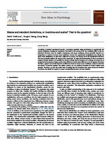
The total cell capacity as a function of CA is shown in Fig. 1 for CC values of 140 and 200 mAh g−1 and for QM = 130.4 mAh g−1 . A slow increase in total capacity is observed until CA reaches 1200 mAh g−1 , after which improvement becomes negligible. At this CA value, total cell capacities will be 63.9 and 74.1 mAh g−1 for CC equal to 140 and 200 mAh g−1 , respectively. However, if anode porosity can also be reduced, allowing reduction in the total amount of electrolyte (e.g., for QM increased by one-third to 173.9 mAh g−1 ), the corresponding total cell capacities will be 72.9 and 86.3 mAh g−1 . This makes it clear that to obtain a noticeable improvement in the specific capacity of Li-ion cells, it is essential to replace carbonaceous anodes with anodes having capacity on the order of 1000–1200 mAh g−1 [7]. Experimental work on anodes using chemical elements which form alloys with lithium was started in early 1960s. In 1971, Dey [8] found that lithium can be electrochemically alloyed with a number of metals at room temperature, including Sn, Pb, Al, Au, Pt, Zn, Cd, Ag, and Mg. However, the alloying process resulted in complete disintegration of the electrodes and loss of electronic contact. Similarly, Sharma and Seefurth [9] reported the formation of Li–Si alloys in high temperature cells operating in the 400–500 ◦ C range. It was reported that the alloying process in silicon anodes results in formation of Li12 Si7 , Li14 Si6 , Li13 Si4 , and Li22 Si5 alloys [10]. Study of the Li–Si binary system [9–11] indicated that each silicon atom can accommodate 4.4 lithium atoms leading to formation of Li22 Si5 alloy, i.e., a specific insertion capacity of 4200 mAh g−1 , the highest among the above alloying elements. In addition to
Fig. 1. Total capacity of 18650 Li-ion cell as a function of anode capacity (CA ), including masses of other required internal components and case. Capacities of cathodes considered were 140 and 200 mAh g−1 .
U. Kasavajjula et al. / Journal of Power Sources 163 (2007) 1003–1039
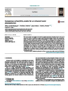
Fig. 2. Galvanostatic charge–discharge profiles for micro-Si (10 m) anode [15].
its outstanding capacity, silicon is the second most abundant element on earth. Because of these attributes, a great deal of attention has been given to using silicon as Li-ion cell anode material. However, the alloying process of Li with Si was found to be less reversible at room temperature [12–14]. As Fig. 2 shows, during the initial cycle a bulk-silicon anode showed a charge capacity above 3260 mAh g−1 and a discharge capacity close to 1170 mAh g−1 , corresponding to a coulombic efficiency of only 35% [15]. During Li insertion into Si in the first cycle, the voltage initially dropped quickly to 0.2 V versus Li/Li+ in the liquid organic electrolyte used,* and then a slow decrease took place as seen in the long potential plateau in Fig. 2. This plateau is due to formation of Li–Si alloys, which co-exist with Si as twophase regions. During the discharge process, a rapid increase in voltage was observed, followed by a plateau between 0.3 and 0.4 V. From the initial charge–discharge profile, it was evident that silicon anodes operate in a narrow potential range between 0.0 and 0.4 V (Fig. 2), which would be suitable for use in Li-ion cells. During further cycling, rapid capacity fade was observed, which resulted in a reversible capacity lower than 500 mAh g−1 by the 5th cycle. Li insertion in Si results in the formation of successive Li–Si alloys, each of which result in progressively larger volume expansions of the parent lattice. Table 1 [10] shows the data for crystal structure, unit cell volume, and volume per silicon atom for each alloy formed during the alloying process. It shows that the volume per silicon atom for Li22 Si5 alloy is four times higher than that of the parent silicon atom, i.e., a 400% Table 1 Crystal structure, unit cell volume and volume per Si atom for the Li–Si system [10] Compound and crystal structure
Unit cell ˚ 3) volume (A
Volume per silicon ˚ 3) atom (A
Silicon cubic Li12 Si7 , (Li1.71 Si) orthorhombic Li14 Si6 , (Li1.71 Si) rhombohedral Li13 Si4 , (Li3.25 Si) orthorhombic Li22 Si5 , (Li4.4 Si) cubic
160.2 243.6 308.9 538.4 659.2
20.0 58.0 51.5 67.3 82.4
1005
volume expansion of the silicon lattice occurs. This results in cracking and disintegration of the electrode, with active material loss via reduced electronic contact, giving severe capacity fade. Although it was initially thought that the low coulombic efficiency of the bulk Si anode was due to low electrochemical reactivity of Li with Si at room temperature, results showed that poor electronic contact between Si particles resulting from the large volume expansion in Si during Li insertion is the real reason for capacity loss. The effect of Si anode volume change on cell capacity can be estimated in a similar way to that in terms of cell capac˚3 ity per unit mass. The LiCoO2 unit cell volume of 95.963 A −3 [16] corresponds to a density of 5.07 g cm [17], giving a cathode volume capacity CC(V) of 659.0 mAh cm−3 . For a graphite anode, CA(V) is 837.5 mAh cm−3 . The corresponding QV value for the 1.8 diameter, 6.5 cm high 154.2 mAh cm−3 Sony 18650 cell is 265.0 mAh cm−3 . Assuming a silicon anode with the maximum insertion capacity of Li4.4 Si (see the following paragraph), a volume expansion corresponding to 400% at this capacity, and an approximately linear relationship between degree of insertion and expansion, the CA(V) values for the LiSi (0.954 mAh g−1 ) and Li4.4 Si (4199 mAh g−1 ) compositions are 1322 and 2446 mAh cm−3 , respectively. Assuming a cathode with a CC(V) 54% higher than LiCoO2 , a graphite anode, and the same QV as that given above would result in a cell giving 168 mAh cm−3 . With a silicon anode, with charge limited to LiSi with the above assumptions, the cell would give 181 mAh cm−3 , while charging to Li4.4 Si would give 193 mAh cm−2 . As before, if QV can be increased by one-third, the corresponding cell capacities per unit volume would be 219 and 237 mAh cm−2 . In each case, the increase in capacity per unit volume on going from LiSi to Li4.4 Si is not dramatic. It is in fact less than the improvement in capacity per unit mass, due to the effect of the volume expansion of Si. To overcome the large volume change and thus obtain better capacity retention and cycle life for Si anodes, various approaches have been used. In this review, we have classified the various approaches to silicon anodes reported in literature into five types, as follows: 1. 2. 3. 4. 5.
Pure Si micro- and nano-scale powder anodes. Si dispersed in an inactive matrix. Si dispersed in an active matrix. Si anodes with different binders. Si thin films.
In this review, we will discuss the current status of approaches to Si- or Si-based anodes and summarize their typical electrochemical performance in tables. We will also describe the challenges that remain to using silicon anodes and give possible approaches to overcome them. The emphasis of the review was initially on the scientific journal literature, which has been covered extensively. However, the experiments described in this literature often occur under conditions differing in certain respects from those in real secondary cells. The major difference is that anodes are generally cycled in the laboratory in a large excess of electrolyte in contact with inert gas at atmospheric pressure,
1006
U. Kasavajjula et al. / Journal of Power Sources 163 (2007) 1003–1039
while while secondary cell components are in contact with a minimum of electrolyte in a sealed container at essentially constant volume. Because lithium insertion anodes show volume changes on cycling, it is apparent that cycling under these differing conditions may give contrasting results, particularly in regard to cycle life. It will be seen that laboratory results usually show rapid capacity fade. During the review process, it was suggested that some of the recent patent literature might throw some light on how to reduce fade under practical conditions. As a result, the review was extended to the recent US patent literature, including published patent applications. The patent review has been selective, rather than exhaustive. High-surface-area electrodes mentioned throughout this review, excluding those in Sections 4 and 5, were made using polyvinylidene fluoride (PVDF, poly-1,1-difluoroethene) binder unless otherwise stated. Readers can find detailed information in the articles cited. Finally, a word of warning to readers. For over 50 years, electrochemists have used the word “discharge” to mean “losing positive electronic charge by combination with an electron.” So, “the hydrogen ion or proton is discharged to become a hydrogen atom.” For some reason, if the ion is negatively charged, as is, say, Cl− , the loss of an electron is not normally called “discharge.” In contrast, for almost 150 years, addition of electrical energy to a secondary cell or battery has been called “electrical charging.” So, battery electrochemists have considered the application of a reductive, i.e., cathodic, reaction, to a secondary cell electrode acting as an anode in the opposite direction (when it produces, rather than takes up, electricity) as “charging the anode.” Thus, to take the familiar example of a metal hydride (e.g., palladium hydride) in acid media, “the proton is discharged to become a hydrogen atom, which diffuses into the palladium insertion matrix, charging it.” The same would be true of the corresponding first step for metal hydride insertion compounds in alkaline media, in which H2 O + e− becomes OH− + H. If one is an electrochemist studying the first step, one would call it hydrogen ion discharge, especially if this step is rate-determining. If one is a battery electrochemist who is more interested in the second step of intercalating hydrogen atoms into the substrate, which is much more likely to be rate-determining in reality, one would call the process “charging.” This dichotomy of nomenclature can become confusing when a sub-set of electrochemists or materials scientists examining lithium insertion half-cells have called the overall cathodic reaction at the anode Li+ + e− → Lisubstrate “the discharge reaction.” The substrate is thereby gaining negative Gibbs energy as it is being electrically charged. After considerable deliberation, we have decided to retain the word “charging” for this process, the main reason being that our interest is in the ability of the substrate to take up lithium atoms, and to release them reversibly, rather than the ability of Li+ to combine with an electron at the surface per se. This convention is used in the text, tables, and figure captions. However, this review has used figures from the original references which could not be easily revised, in which “charging the substrate” is called “discharge,” i.e., that of Li+ ion, and vice versa. In these, the figures internally contain the word “discharge” meaning Li atom intercalation, and “charge” meaning dealloying. So a “charge–discharge curve” to a battery
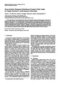
electrochemist becomes a “discharge–charge curve.” Those in question are Figs. 5, 7, 8, 13, 15, 17 and 18. The captions of these figures are marked§§ . The authors believe that this review is as complete as might be achieved up to a journal literature cut-off date of June 15, 2006. They would be grateful if readers would point out any omissions. 2. Pure Si powder anodes This Section discusses the electrochemical performance of anodes made from pure Si powders. The methodology for reducing Si particle size to that required to reduce volume expansion is discussed. When particle size was reduced to micrometers, no particular improvement in electrochemical performance was observed. As for bulk Si anodes, those fabricated from microSi powder also showed a large irreversible capacity and poor capacity retention. 2.1. Explanation of the high irreversible capacity and poor cycle life of micro-Si anodes To understand the reasons for the poor cycling stability of micro-Si anodes, their internal electrochemical resistance was measured during charge–discharge cycling by the galvanostatic intermittent titration technique (GITT) [15]. In this, a current pulse of 100 mA g−1 was applied for 10 min to measure the closed-circuit voltage (CCV) for the composition that had been previously obtained galvanostatically. The current was then turned off for 20 min to obtain the quasi-open-circuit voltage (QOCV) for this composition. Transient voltage profiles obtained from such GITT measurement are shown in Fig. 3(a). From these, the internal reaction resistance was obtained by calculating the difference between the CCV and QOCV for each voltage transient [15]. Its variation during the charge–discharge process is shown in Fig. 3(b). This shows that during the alloying process the internal reaction resistance decreases, since Li–Si alloys have a higher electronic conductivity than that of pure silicon. During de-alloying, the resistance increases, since volume contraction takes place, giving less effective electronic contact between particles with an increase in contact resistance and charge transfer resistance. As a result, complete de-alloying cannot take place because of trapping of Li+ ion inside the anode host particles. This was confirmed by imposing pressure during de-alloying, which considerably increased the charge capacity by improving electronic contact between the active particles and the current collector. These results suggested that de-alloying is more detrimental to Si anode cycle life than alloying. The poor cycling performance of silicon anodes was due to breakdown of the electronically conductive network, which resulted from the large Si volume expansion. It should be noted that the internal reaction resistances calculated from the difference between the CCV and QOCV within each voltage transient or local composition are only approximate, and their accuracy decreases with increasing reaction overpotential. A more accurate in-situ method to directly measure the internal contact
U. Kasavajjula et al. / Journal of Power Sources 163 (2007) 1003–1039
1007
Fig. 4. Potential and intrinsic resistance of anode with 60 wt% Timcal KS-15 graphite, 20 wt% nano-Si, 10 wt% carbon black, 10 wt% polyvinylidene fluoride (PVDF) during first cycle at 5 mA g−1 charge, 10 mA g−1 discharge. Current for intrinsic resistance measurement: 5 mA [19]. Fig. 3. (a) Transient voltage profiles for micro-Si anode obtained using the galvanostatic intermittent titration technique (GITT). Inset: A typical voltage transient obtained in one current pulse cycle. (b) Internal resistance of micro-Si anode calculated from transient voltage profiles [15].
and reaction resistances of the electrode during insertion and extraction was developed by us using two potentiostats [18], which allowed these resistances to be measured successfully for graphite anodes [18]. The same technique was used to measure the contact resistance of graphite–silicon composite anodes during charge–discharge, as shown in Fig. 4 [19]. In contrast to a graphite (G) electrode, the internal contact resistance of G–Si composite electrode increased continuously during both Li-insertion and extraction. This effect results from pulverization of Si during Li-insertion and its shrinkage during extraction. These results suggest that both Li-insertion and extraction are detrimental during Si anode cycling. 2.2. Technologies to improve the performance of Si anodes One way to improve electronic contact between particles during insertion and extraction is by mixing conductive additives (CA) such as graphite flakes and/or nano-scale carbon black into micro-Si anodes [20]. Increasing CA content dramatically increased the cycle life and irreversible capacity of silicon anodes due to the increased interparticle electronic contact, which gave improved Li de-alloying kinetics and also prevented
the agglomeration of Si particles. The buffering action of soft CA particles also suppressed the large Si volume change on some degree, relieving mechanical stresses inside the anode. A second way to improve Si anode performance is to decrease Li insertion/extraction levels by narrowing the cycling voltage window [20]. A third and most widely studied method is to reduce the Si particle size to nano-scale [21,22] using laser-induced silane gas reaction [21]. Fig. 5 shows voltage versus capacity curves for nano-Si anode. It shows that a charge capacity of 2775 mAh g−1 and a discharge capacity close to 2097 mAh g−1 could be obtained for a nano-Si anode during the first cycle, giving 76% coulombic efficiency. Its reversible capacity on the 10th cycle was 1729 mAh g−1 , i.e., the capacity fade was much lower than that of a bulk Si because of smaller volume expansion due to reduced particle size. While particle size reduction can reduce volume change to a certain degree, it cannot completely eliminate capacity fade. 3. Si-inactive material composites Another method used to suppress Si volume expansion has been to create a composite structure consisting of an inactive host matrix in which silicon is finely dispersed. An inactive matrix used in the anode acts as a cushion and accommodates the volume change in the Si active material, thereby preventing
1008
U. Kasavajjula et al. / Journal of Power Sources 163 (2007) 1003–1039
Fig. 5. §§ Charge–discharge curves between 0.0 and 0.8 V at 0.1 mA cm−2 for nano-Si anode with 4:4:2 weight ratio of nano-Si, carbon black and PVDF binder. Electrolyte: 1 M LiPF6 in ethylene carbonate (EC)–diethyl carbonate (DEC) (1:1) [22].
pulverization of the anode. This inactive matrix must have a high mechanical strength to withstand the volume change of Si on cycling. Ideally, it should also have high electronic conductivity to allow charge transfer reactions to take place. Metallic compounds such as TiN [23], TiB2 [24], SiC [25], and TiC [26,27] have been examined for this purpose as inactive host matrices. These were mixed homogenously with Si by ball milling to obtain a powder to prepare anodes. X-ray diffraction (XRD) results for ball-milled samples showed that the Si in these was amorphous, while the inactive material was nano-crystalline or amorphous. When cycled between 0.02 and 1.2 V, such anodes showed stable reversible capacities of 300–400 mAh g−1 for 15 cycles. These capacities were low compared to their theoretical values of 700–900 mAh g−1 . With a reduced ball milling time, they showed higher reversible capacities, but with poor cycle life. When the inactive phase was pre-milled and then again milled with Si, anodes made from the powder thus obtained showed better capacity retention than anodes containing a non-milled inactive phase [27]. This was due to the smaller particle size of the inactive matrix, which increased buffering action, giving uniform distribution of stress throughout the electrode. Scanning electron microscopy (SEM) analysis showed that their surfaces remained crack-free after galvanostatic cycling, indicating their good structural stability. However, their reversible capacities were still low, perhaps due to poor Li+ ion diffusivity in the inactive matrix, which limited reaction of Li with Si. To improve the electrochemical performance of Si–TiN or Si–TiB2 composite anodes, a carbon coating technique was examined [28,29]. This was conducted by pyrolyzing a mixture of ball milled Si–TiN or Si–TiB2 composite powders with coal tar and polyvinyl chloride (PVC) in 3:7 weight ratio at 900 ◦ C for 1 h. Independent of the matrix, all Si anodes prepared by this method showed similar charge–discharge characteristics and trends in potential. Compared to Si–TiM, where M is the N/B ratio, carbon coated Si–M anodes showed higher cycling stability [28]. Their improved
cycling performance was attributed to carbon coating from pyrolyzed PVC, which acted as an elastic binder network, resulting in an increase of anode electronic conductivity and mechanical integrity. Finally the encapsulation of Si in a carbon-M composite structure led to better accommodation of the volume change with nano-Si active material. Similarly, Si M C electrodes were prepared by two pyrolysis reactions with one intermittent high-energy mechanical milling (HEMM) of the same precursors in similar ratios [29]. In the cycling voltage range 0.05–1.5 V, this anode showed an initial reversible capacity of 800 mAh g−1 , and in the 35th cycle it showed a capacity retention ability of 90% of that of the second cycle (600 mAh g−1 ). A lower reversible capacity of this anode compared with one prepared by pyrolysis appeared to be due to the smaller percentage of Si present in the latter. As well as good capacity retention, anodes prepared by two pyrolysis steps and one HEMM step showed high rate capability. This was due to high electronic conductivity of the anode resulting from the presence of the inactive metallic matrix and the high carbon content obtained from the two pyrolysis reactions. Other than metal nitrides and metal carbides, metal oxides such as TiO2 and ZrO2 have also been examined by sol–gel coating onto Si particles in the patent application literature [30]. Within an operating voltage window of 0.0–1.2 V, these were claimed to have stable reversible capacities between 800 and 900 mAh g−1 for 16 cycles. Several other Si compounds containing inactive host matrices (M), such as SiB3 , CaSi2 , CoSi2 , FeSi2 , and NiSi2 were investigated as Li-ion anodes by Netz et al. [31]. Initial discharge capacity, Li extraction ratio, and molar weight for these anodes are listed in Table 2. Among them, CaSi2 and NiSi2 showed the highest reversible capacities, equal to 1.15 and 0.85 Li mol−1 , while CoSi2 and FeSi2 had the lowest at 0.25 Li mol−1 . The high initial reversible capacity of the CaSi2 anode merited further investigation [32]. Based on the predicted Ca–Si–Li room temperature phase diagram, the following reaction was proposed for the Li insertion reaction in a CaSi2 anode. 10.8Li + CaSi2 → Li2 Ca + 2Li4.4 Si It is evident that metallic Li alloys with Si in this compound, forming the range of Li–Si alloys. When charged–discharged between 0.005 and 1.5, it exhibited a charge capacity above 1500 mAh g−1 , which was reduced to 310 mAh g−1 after 10 cycles. Beyond pulverization during Li insertion/extraction, another reason for its poor cycle life was explained by the mechanical properties of the alloy matrix, particularly its meltTable 2 Specific capacity data for several materials [31] Precursor
Molar weight
First delithiation (Li mol−1 )
Delithiation capacity (mAh g−1 )
CoSi2 FeSi2 NiSi2 CaSi2 SiB3 SiO ␣-Silicon
115.11 112.03 114.87 96.26 60.52 44.09 28.09
0.25 0.25 0.85 1.15 1 1.1 1.05
58 6 198 320 443 669 1002
U. Kasavajjula et al. / Journal of Power Sources 163 (2007) 1003–1039
ing point, elastic modulus, and ductility. It is known that elastic modulus and ductility are directly and inversely proportional to melting point, respectively. Generally Ca–Si alloy matrices have lower melting temperatures, and high ductility and elastic modulus. This means that they cannot sustain large volume changes, and so have severe capacity fade during initial cycling. The results obtained suggested that Si dispersed in a matrix with a high elastic modulus and low ductility might relieve tensile stresses during the reaction of Li with Si, making it an excellent candidate for a Li-ion cell. Thus Si3 N4 [33], whose hardness is employed in tools, and Si3−x Fex N4 [34] were also investigated as anodes. When charged to 0.01 V, Si3 N4 [33] showed a capacity of only 83 mAh g−1 , considerably less than that of graphite, suggesting that hardness results in low Li insertion ability. To increase reversible capacity, Fe was added to Si3 N4 , which was then ground and calcined to form the composition Si3−x Fex N4 [34]. XRD results showed that it consisted of solid solution of Si3 N4 and Fe. When used as an anode, this compound showed an improved specific capacity compared with that of an Si3 N4 anode, which was explained by the presence of vacant Fe sites acting as Li intercalation/deinteracalation centers. Although Si3−x Fex N4 had a reversible intercalation capacity four times higher than that of Si3 N4 , it was still too low for commercial application. Apart from hard metallic compounds such as TiN, mediumstrength metals with high electronic conductivity such as Ni [35,36], Fe [36], and Cu [12] were also selected as a matrix to form alloy anodes by mechanical milling. With Ni, the resulting anode was found to have a homogenous NiSi phase, while with Fe, it contained FeSi and Si phases, the latter having a large particle size. Based on the active and inactive elements present in the alloy anodes, the following reaction mechanisms were proposed for Li insertion and extraction. xLi+ + xe− + NiSi → Lix Si + Ni → Ni + Si + xLi+ + xe− xLi+ + xe− + FeSi → Lix Si + Fe → Fe + Si + xLi+ + xe− In the proposed mechanisms, the theoretical value for NiSi is 1360 mAh g−1 if all the Si reacts with Li to form Li4.4 Si. Ni and Fe are present in the elemental state after the first charge and discharge process. It was thought that the elemental Ni and Fe formed during initial charge would act as buffering matrix to suppress the Si volume change. Though both of these anodes have shown similar initial reversible capacities, NiSi showed better capacity retention than FeSi [36]. The poor cycle life of FeSi was due to the large particle size of unalloyed Si, which resulted in a large overall anode volume change. To improve the cycling stability of FeSi alloy, an alloy was prepared by annealing Fe and Si powders at 1000 ◦ C, followed by milling. Annealing was performed to increase the binding strength between Fe and Si [37]. The powder obtained from ballmilling was mixed with graphite to improve buffering action in the anode and the composite was again ball-milled. From XRD analysis, FeSi alloys prepared by annealing were found to contain ␣-FeSi2 and -FeSi2 . It was thought that Si particles were embedded in the FeSi2 compounds, which would act as buffering matrix. However, such FeSi alloys showed low reversibility and
1009
poor cycle life. Poor cycling performance was attributed to the small amount of FeSi2 phase present in the anode, which could not completely cover all the Si particles. When graphite was added to the alloy powders, it resulted in a first charge capacity of 800 mAh g−1 . After 25 cycles, it showed a charge capacity of 550 mAh g−1 , so addition of graphite resulted in increased reversible capacity and improved cycling performance. While the Fe–Si/graphite anode showed better electrochemical performance, it also had 100% irreversible capacity, which is a potential disadvantage. Similar results were also reported for Fe–Si/G composite anodes prepared from ball milling of commercially available Fe–Si alloy and graphite [38]. X-ray photoemission spectroscopy (XPS) showed that the Fe–Si/G anode has a composite structure, with graphite as an outer shell, and with FeSi alloy containing dispersed Si particles as a middle shell. Li insertion into Fe–Si/G was predicted to be: FeSi2 + Si + G + yLi+ + ye− → Liy−z Si + Liz G + FeSi2 The improved cycling performance of Fe–Si/graphite was attributed to its “sandwich” structure, which suppressed the Si volume change. To further improve the cycling stability of Fe–Si–graphite, Ba was added to this alloy by ball milling [39]. XRD patterns of a Ba–Fe–Si/G anode before charging and discharging consisted of peaks identified as BaSi2 and FeSi2 alloys. Based on XRD and XPS results, the following Li insertion mechanism was proposed for Ba–Fe–Si/G: Ba–Fe–Si/C + xLi+ + xe− → Liy Si + Lix−y C + BaSi2 + FeSi2 Compared to pure Si anodes, Ba–Fe–Si anodes showed better cycling performance. The reason for improvement was considered to be due to the presence of BaSi2 and FeSi2 alloys which acted as inactive buffering matrix to offset the Si volume change. However, after 15 cycles, the Ba–Fe–Si anode showed a reversible capacity less than 400 mAh g−1 . When graphite was mixed with this alloy powder, it resulted in a reversible capacity of 420 mAh g−1 after 15 cycles. The improvement was attributed to graphite preventing aggregation of alloy particles. However, the capacity retention ability of such anodes was less than that of Fe–Si/G. The reason for their poor capacity retention was unknown. Ni–Si/G composite was also synthesized by arc-melting followed by HEMM. It showed improved cycling stability [40] (Fig. 6). Improved cycling stability was attributed to better accommodation of the volume change, which resulted from the presence of NiSi, NiSi2 phases, and disordered graphite layers. Further efforts were made by Lee et al. [41] to improve the cycling performance of Ni–Si/G anodes by carbon coating. Initially Ni20 Si80 alloys were prepared by milling Ni and Si powders. The Ni20 Si80 alloy powders thus obtained were milled with graphite to form Ni20 Si80 graphite composite. Carbon was coated onto this composite by mixing it with coal tar pitch, then pyrolyzing at 900 ◦ C for 1 h. XRD patterns of carbon-coated composite indicated crystalline NiSi2 and Si phases. Compared to untreated Ni–Si/C anodes, those coated with carbon showed better capacity retention due to the enhanced conductive contact
1010
U. Kasavajjula et al. / Journal of Power Sources 163 (2007) 1003–1039
Fig. 6. (a–c) Cycle performance of Si/Ni alloy/graphite composites with different alloy to graphite weight ratios: (a) 7:3, (b) 6:4, (c) 5:5, and (d) Si/carbon (5:5) composite [40].
between Ni20 Si80 alloy and graphite particles, and surface modification. However, a decrease in reversible capacity close to 250 mAh g−1 was observed with carbon-coating. The reason for this reduction was unclear. Unlike mechanically-milled Ni–Si and Fe–Si alloys, Cu–Si was formed by electroless deposition of Cu on Si powder [12]. To increase adhesion between Cu and Si, Cu was deposited on etched Si, followed by annealing at 400 ◦ C. The Cu-coated Si powder showed higher electronic conductivity than the untreated material. However, its conductivity was reduced during annealing, which resulted in formation of resistive Cu3 Si alloys. When charged–discharged between 0.0 and 2.0 V, the Cu-coated Si electrode showed good capacity retention but unsatisfactory cycle life because of Cu detachment from the Si surface after few cycles, as was observed by SEM analysis. Increased Cu content with more effective annealing gave improved capacity retention and better cyclability. Its improved capacity retention resulted from its increased conductivity, which reduced contact and charge transfer resistances during alloying/ de-alloying. Apart from Ni–Si, Fe–Si, and Cu–Si alloys, highly oxidationresistant alloys such as C–B–Si–N compositions were also investigated. They were prepared by co-pyrolysis of a light petroleum pitch fraction with polydimethylsilane followed by co-pyrolysis of the product with borane and pyridine, followed by heat treatment under nitrogen at 1200 ◦ C [42]. When cycled at low current densities (0.01 mA cm−2 ), a C–B–Si–N alloy anode showed a reversible capacity of 500 mAh g−1 and a columbic efficiency of 73%. Cycling performance of these anodes was not reported. It had been reported earlier that Li insertion into tin oxides resulted in the formation of metallic Sn and an inert Li2 O matrix [43], which was believed to alleviate the volume change when Li alloys with Sn. Due to the superior cycling stability shown by tin oxide materials, silicon oxide powders with different oxygen contents (SiO, SiO0.8 , SiO1.1 ) were also investigated as Li-ion anode materials [44]. Among anodes with differ-
Fig. 7. §§ Cycling behavior of SiOx with different oxygen content and particle size [44].
ent oxygen contents tested, those with lower oxygen content (SiO0.8 ) showed higher reversible capacities (1600 mAh g−1 ) but had poor capacity retention (Fig. 7). In contrast, anodes with higher silicon content (SiO1.1 ) showed stable reversible capacities of 800 mAh g−1 over 25 cycles (Fig. 7). When the particle size of SiO1.1 was reduced from 50 to 30 nm, capacity retention was further improved. Although high specific capacities and better cycle life were obtained with these anodes, they showed 50% irreversible capacities on the first cycle, which is undesirable for practical Li-ion cells. Their high irreversible capacity was due to formation of Li2 O, which was confirmed from neutron elastic scattering experiments [45]. To reduce the irreversible capacity of SiOx anodes, Li was doped into them by the following procedure [46]: initially, an electrode was made from SiO powder on a nickel foam substrate, which was then immersed in a Li–organic complex solution obtained by dissolving naphthalene and metallic Li wrapped in porous polyethylene film into butyl methyl ether (BME) solvent. During immersion, naphthalene acted as a catalyst for doping Li into the SiOx . When the electrode thus formed was immersed in electrolyte for 72 h, its equilibrium potential fell, finally stabilizing at 0.21 V versus Li/Li+ . Its discharge capacity was 670 mAh g−1 , which was higher than than that of pure SiOx electrode, and its irreversible capacity was reduced. The extraction potential versus Li/Li+ of such anodes is also raised. The resulting reduction in power density makes these materials unsuitable for commercial use. Because of the advantageous electrochemical performance of lithium–transition metal oxynitrides as anode materials [47], lithium silicic oxynitride composites (LiSiPONS) prepared by HEMM of SiO2 and Li3 N powders were investigated [48]. Although a reversible capacity of 600 mAh g−1 and a stable cycle life of 100 cycles were obtained, when the electrode was charged–discharged between 0.0 and 3.0 V, 75% of the capacity was obtained above 1.5 V, which cannot be considered to be practical.
U. Kasavajjula et al. / Journal of Power Sources 163 (2007) 1003–1039
Although the cycling stability of powder-based anodes prepared from Si covered by an inactive matrix was much better than that of pure Si anodes, it was not enough for commercial application. Recently, Sony has marketed its next generation Li-ion cells (Nexelion) which show a 30% capacity increase by using tin-based amorphous substrates. The large volume changes of tin anodes during Li insertion and extraction have been overcome by using alloys of the general formula SnM1x M2y M3z [49], where M1 , M2 , M3 are Co, Cr, and In. After testing anodes with M = 0.2 < x < 1 for all three compositions, a 92% capacity retention ability was observed. Since Co, Cr, and In do not react with Li, they can limit the change in particle shape and size and thus increase cycling stability. As a result, volume change was minimized, promising greatly improved Sn anode cycling stability. The electrochemical performance of the anodes discussed in this Section shows that covering silicon with an inactive matrix reduces reversible capacity. When an active matrix such as graphite or pyrolyzed carbon is used to replace part of the inactive matrix, an increase in both reversible capacity and capacity retention are observed. To further improve Li-ion insertion ability, the outer inactive matrix should be completely replaced by an active matrix. In the next Section, the electrochemical performance of Si anodes covered by different active matrices is discussed. 4. Si-active material composites 4.1. Si-metal composites Metallic silver and magnesium can reversibly react anodically with Li+ at room temperature and form alloys (see Section 1). Mg2 Si alloy was therefore investigated as an anode material [50]. When charged–discharged between 0.0 and 1.5 V and 0.0 V at 10 mA g−1 , they showed a charge capacity of 1370 mAh g−1 and a discharge capacity of 1074 mAh g−1 . The charge capacity was equivalent to insertion of 3.9 Li atoms per Mg2 Si atom, which faded rapidly to only 100 mAh g−1 after 10 cycles. To understand this capacity fade, the Li-insertion reaction mechanism was studied by ex-situ XRD and atomic emission spectrography (AES). Differential capacity plots obtained for Si, SiO, and Mg were compared with those for Mg2 Si. It was determined that Si-containing materials followed similar Li insertion/extraction mechanisms because of the formation of Li–Si alloys, and the Li insertion mechanism in Mg and Mg2 Si anodes was the same near 0.0 V. Based on the XRD and AES analyses, the following reaction mechanism for Mg2 Si was proposed by Kim et al. [51]: First step : Mg2 Si + xLi+ + e− → Lix Mg2 Si Second step : Lix Mg2 Si + Li+ + e− → Licritical Mg2 Si → Lisaturated Mg2 S + Mg + Li–Si alloy Final step : Mg + Li+ + e− → Li–Mg alloy It was therefore proposed that Li insertion into Mg2 Si was via three steps. First, Li inserts into octahedral Mg2 Si sites to form
1011
Lix Mg2 Si. When the Li concentration in Lix Mg2 Si reaches a critical value at 0.17 V, it decomposes into Lisaturated Mg2 Si, Mg, and Li–Si alloy phases as in Step 2. Finally, further insertion takes place into the Mg formed Step 2 with the formation of Li–Mg alloy. During extraction, the reverse reactions occur with formation of Mg2 Si. However, a small amount of Mg was still observed at the end of extraction. Comparison of XRD data for fresh and cycled anodes showed the presence of Li–Mg and Mg phases at the end of extraction. These incomplete reactions may be the reasons for capacity fade, since lithium is then trapped inside the anode. Li insertion into the remaining Mg phase results in volume change, which adds to that resulting from insertion into Mg2 Si, leading to cracking and disintegration of electrodes. A similar reaction mechanism was proposed by Moriga et al. [52] and Roberts et al. [53]. The latter [53] prepared Mg2 Si powders by ball milling and annealing of Mg and Si powders. In both cases, formation of Li2 MgSi was observed instead of LiMg2 Si. However, the formation of Li–Si phases was not reported. This may be due to the high current densities used, which reduced the kinetic possibilities for Li–Si reactions. While the Li insertion mechanism in Mg2 Si anodes observed in both these cases [52,53] is somewhat different from that previously reported [51], severe capacity fade was observed in all three cases, showing the inability of Mg2 Si anodes to suppress or accommodate volume changes on cycling. SiAg anodes prepared by ball milling Si and Ag for 2, 15, and 50 h have also been examined [54]. XRD showed that Si was nano-scale and SEM analysis showed uniform dispersion of Si and Ag inside the anode. However, mechanical cracking due to the Li-insertion volume change resulted in poor cycling. Similarly, SiAg anodes prepared by electroless plating of Ag particles on Si powder were also tested [55]. X-ray energy dispersion analysis (EDAX) showed that the Si surface was covered by Ag particles. The improved performance of Agdeposited Si was attributed to formation of an SEI film, which was not observed in pure Si anodes. The SEI film was believed to maintain contact between the pulverized Si particles. However, no galvanostatic cycling performance was reported for these anodes. Sn is another metal allowing reversible Li insertion/extraction (see Section 1), so Si–Sn alloys with different compositions have been investigated as anodes. Among samples tested, a-Si0.66 Sn0.34 film (a- = amorphous) showed high electronic conductivity. When charged–discharged between 0.0 and 1.3 V, a-Si0.66 Sn0.34 anodes had an initial charge capacity of 2000 mAh g−1 and a discharge capacity ≈1900 mAh g−1 [56]. Charge–discharge curves were found to be smooth with no plateaus. Similarly, no sharp peaks were observed in differential capacity plots, which indicate the phase stability of the material during cycling. To determine their reaction mechanism, in-situ XRD experiments were conducted during cycling. Results showed that the film always remained amorphous. At the end of charge, a-Li4.4 Si0.66 Sn0.34 was formed. While high reversible capacity was obtained with a-Si0.66 Sn0.34 , its cycle life is as yet unknown. In the patent literature [57], efforts were made to improve electronic pathways between the current collector and Si active
1012
U. Kasavajjula et al. / Journal of Power Sources 163 (2007) 1003–1039
material by forming multi-layer particles with Si inner, intermetallic middle, and synthetic graphite outer layers to give as-prepared active material containing between 30 and 70 wt% Si. Intermetallics such as Mg2 Si, CoSi2 , NiSi2 , were claimed. The middle layer was intended to suppress the cycling volume change, while the outer layer increased electronic conductivity. Previous attempts to mix conductive agents into the anode to improve its electronic conductivity resulted in too small an electronic contact area, which resulted in major cycling fade for anodes showing large volume changes. This effect was prevented by surface coating of the intermetallic compound by fusion, then subjecting the resulting powder to mechano-fusion to coat synthetic graphite onto the surface. This gave an anode with greater than 80% capacity retention over 300 cycles. A similar approach in published US patent applications [58–60] has involved dispersing Si into a metal (Sn, Zn, Al) acting as an active matrix, but including a lesser proportion of another inactive metal (Cu, Co, Ni, Ti, B, Sb). Impregnation was done via melting the elements with Si to form an alloy, followed by water atomization and HEMM. The resulting powder contained uniformly-dispersed Si in an active metal matrix and an intermetallic compound, e.g., Cu6 Sn5 , Cu5 Zn8 , Ni3 Sn2 , etc.) formed from an Li-active and Li-inactive metal. When charged–discharged between 1.2 and 0.0 V for 30 cycles, such anodes showed reversible capacities in the 1100–1700 mAh g−1 range [58–60]. In particular, Si–Sn–Ni alloy anode showed superior capacity retention ability [58]. A charge–discharge test in a complete cell using a LiCoO2 cathode and one of the above anode anodes gave a capacity retention of 75% at the 100th cycle [58]. The improved cycling stability of this anode may be due to the minimization of volume change by dispersing Si in the complex matrix. 4.2. Si/C composites Although the cycling performance of Si-metal inactive/active matrix composite anodes discussed in the last Section is much better than that of pure Si anodes, capacity fade has still been unavoidable. Even relatively strong metals may not be able to sustain the 400% volume expansion of Si, and their pulverization will result in loss of interparticle electronic contact. Carbon has been used as an active matrix because of its softness and compliance, relatively low mass, good electronic conductivity, reasonable Li-insertion ability, and small volume expansion. Silicon dispersed in carbon matrices (Si/C composites) were therefore tested as anodes. Various methods have been employed for preparing Si/C composite anodes. Based on their preparation procedure, we classify Si/C composite anodes into five types: 1. Pyrolysis or chemical/thermal vapor deposition (CVD/ TVD). 2. Ball milling or mechanical milling. 3. Combination of pyrolysis/CVD/TVD and mechanical milling. 4. Chemical reaction of gels. 5. Other methods.
Fig. 8. §§ Capacity vs. cycle number for anode made from polymethylphenylsiloxane (PMPS) pyrolyzed at 1100 ◦ C [61].
4.2.1. Si/C composite anodes prepared by pyrolysis reactions or TVD. Work on Si/C composite anodes started in the early 1990s. Dahn et al. appear to have been the first to prepare Si/C composites from various polymers containing silicon and carbon. The first anode was prepared from thermal pyrolysis of polymethylphenylsiloxane (PMPS) and polyphenylsesquisiloxane (PPSSO) polymers in the 900–1300 ◦ C temperature range [61]. These start to decompose above 500 ◦ C, rapidly evolving large amounts of benzene and small amounts of methane and hydrogen at higher temperatures. Thermogravimetric analysis (TGA) showed final estimated compositions at 1000 ◦ C as C2.9 SiOHy and C3.9 SiO1.5 Hy , respectively, with y ranging from 0 to 1. Both were amorphous and had reversible capacities of 550 mAh g−1 and an irreversible capacity close to 300 mAh g−1 (Fig. 8). When pyrolysis was performed at 1300 ◦ C and above, anodes showed low reversible capacities (close to 200 mAh g−1 ) and large irreversible capacities because complete oxygen removal occurred with formation of silicon carbide. Siloxane polymers were also synthesized and investigated as anode materials [62,63]. They were derived from mixtures with generic structures (R1 R2 R3 SiO0.5 )w (R4 R5 SiO)x (R6 SiO1.5 )y (SiO4/2 )z , where R1 –R6 are hydrogen or alkyl groups and w, x, y, and z are molar ratios [63]. Their electrochemical performance was explained by constructing a Gibbs triangle for Si, C, and O. Most of the samples lay near the line connecting carbon to SiO1.3 . Along the line, reversible capacities increased from 340 mAh g−1 for pure carbon, to a maximum capacity of 890 mAh g−1 for the composition of 25 wt% Si, 45% C, and 30% O. When the amount of carbon was further decreased, it led to a decrease in reversible capacity with 0 mAh g−1 capacity at 0% carbon. These results indicate the role of carbon in improving their reversible capacity. Although amorphous Si C O glass can reversibly react with Li, conduction pathways for electrons and Li+ ions are necessary, which are provided by carbon. XRD of the composition 25% Si, 45% C, and 30% O showed that it consisted of amorphous Si C O glass dispersed in disordered carbon. From comparison of stoichiometries, it was concluded
U. Kasavajjula et al. / Journal of Power Sources 163 (2007) 1003–1039
that increase in oxygen content increased irreversible capacity and discharge potential. Although higher specific capacities were obtained with pyrolyzed polysiloxane materials, samples with desired Si/C compositions could not be prepared, since the Si/C compositions of the polymer precursor was fixed. To prepare anodes with desired Si/C compositions, an epoxysilane composite was prepared from the non-silicon-containing polymer poly[(phenylglycidylether)-co-formaldehyde)], an epoxy resin, and the epoxy-functional silane 3-glycidoxypropyltrimethoxysilane [64]. The epoxy-silane composite obtained was pyrolyzed at 1000 ◦ C and the resulting powder made into an anode. When epoxy resin was pyrolyzed, it gave disordered carbon in the form of single graphene layers. Pyrolysis of silane gave an amorphous glassy compound with the composition C0.5 Si0.19 O1.31 . Pyrolysis of the epoxy-silane composite gave a compound of composition C1−y−z Siz Oy . The amount of carbon was found to depend on the silane concentration in the precursor, first increasing, then decreasing as silane increased. An optimum composition was obtained using 50% silane and 50% resin, which gave a mixture of carbon single layer phase and amorphous glassy phase. As the amount of silicon and oxygen in the anode was increased, the reversible capacity also increased. Increase in silicon and oxygen concentration also resulted in increase in charge potential, which led to significant capacity above 1.0 V. When the anode was made from 50% silane and 50% resin, it showed a reversible capacity of 770 mAh g−1 , but with a large irreversible capacity. Although Si/C composite anodes with desired compositions can be prepared by the epoxy-silane approach, the large irreversible capacities observed for these materials were disadvantageous. Apart from polysiloxanes and epoxy-silanes, pitchpolysilane composites in various ratios were also pyrolyzed at 1000 ◦ C to form Si/C composites [65]. Stoichiometries of these samples corresponded to the entire region of the C, SiC, and SiO2 Gibbs triangle. As with the epoxy-silane composite precursors, anode materials prepared from material with higher silane content exhibited an amorphous glassy structure dispersed in disordered carbon. Increasing silane in the pitch blend increased both reversible and irreversible capacity. A study of electrochemical performance as a function of composition led to the conclusion that materials in the SiO2 and SiC corners should not be used for the preparation of Si/C composite anodes. Using these results, a silane polymer with composition (Me2 Si)x (PhMeSi)y was selected for further investigation [66]. As with the anodes made from siloxane polymers [63], the presence of oxygen was found to be the main reason for high irreversible capacity. This was confirmed from X-ray absorption spectroscopy (XAS) and charge–discharge curves, where the presence of oxygen gave an additional plateau between 0.6 and 0.8 V. The effect of oxygen and sulfur content on Si/C irreversible capacity was examined by electrochemical tests on anodes containing pyrolyzed mixtures of pitch and polysilanes [67,68]. Polyphenylmethylsilane (PPMS), polydimethylsilane (PDMS), polydimethylphenylmethylsilane (PDMPMS), polydiphenylsilane (PDPS), and PDMS/PPMS and PDMS/PDPS mixtures were used along with Ashland Chemical pitches with differ-
1013
ent sulfur contents, naphthalene pitches, and PVC pitch with very low sulfur and oxygen content. Anodes made from pitches other than PVC pitch showed irreversible capacities between 150 and 170 mAh g−1 . When PVC pitch was used, a considerable decrease in irreversible capacity was observed. However, it also resulted in reduction in reversible capacity due to loss of active Si and inactive Si C phase formation. When significant amounts of Si and S were present, a large amount of Li was inserted, but it also resulted in increased irreversible capacity since some Li was trapped by S. Similarly, reversible capacity between 320 and 450 mAh g−1 and irreversible capacities of 300 mAh g−1 were reported for Si/C composite anodes prepared by pyrolysis of coal tar pitch and silane polymers, such as PDMS, PPMS, PDMPMS, and PDPMPS [69]. From these results, it was concluded that pitch-polysilane blends were not suitable for preparing anodes with high reversible and low irreversible capacities. Similarly, Hayes et al. [70] reported formation of Si/C composites from polymethacrylonitrile/divinylbenzene (PMAN/DVB) copolymer as a carbon precursor and tetramethylsilane (TMS) or tetravinylsilane (TVS) as Si precursor. These were mixed to form an emulsion which was polymerized at 65 ◦ C, thermally stabilized in air at 240 ◦ C, and finally pyrolyzed at 700 ◦ C. The resulting material was found to have large oxygen content (22.5 wt%), negligible nitrogen content (2.99 wt%), and 10 wt% Si. Structural studies showed that the material consisted of mostly Si O Si bonds with a few Si O C bonds, but no Si C bonds, possibly showing that these were converted to Si O C bonds during oxidative stabilization, with further conversion to Si O Si bonds during pyrolysis. These Si O Si and Si O C glasses were found to be dispersed in disordered carbon. When cycled between 0.10 and 1.0 V, anodes made from PMAN/DVB–TMS emulsion showed a reversible capacity of 394 mAh g−1 with a large irreversible capacity of 576 mAh g−1 . The anode made from PMAN/DVB–TVS showed a reversible capacity of 363 mAh g−1 and an irreversible capacity of 601 mAh g−1 . Their first cycle columbic efficiency was 26%, which was very low compared with the columbic efficiency of Si/C composite anodes obtained from pitch-polysiloxane materials [63]. Although the structures of the both materials were the same, the reversible capacity was very low for anodes made from PMAN/DVB–TVS/TMS. The difference in electrochemical performance was attributed to the different polymer precursors used. Li intercalation into the last anode resulted in formation of silicates, accounting for their irreversible losses. Their large irreversible capacities and low reversible capacities make the above materials unsuitable as anodes. The electrochemical performance of Si/C composite anodes prepared by pyrolysis of various polymer precursors makes it clear that the presence of oxygen in the anode leads to irreversible capacity. To overcome this, oxygen free materials have been used as carbon and silicon precursors. Wilson et al. [71,72] used benzene as a carbon precursor, with SiCl4 and (CH3 )2 Cl2 Si as Si precursors. Precursor materials were deposited by thermal vapor deposition (TVD) at 850, 950, or 1050 ◦ C. The materials obtained showed the absence of a-Si, SiC, and SiO2 . It was thought that Si was located in unorganized graphitic regions.
1014
U. Kasavajjula et al. / Journal of Power Sources 163 (2007) 1003–1039
Anodes made from this material showed reversible and irreversible capacities of 640 and 120 mAh g−1 , respectively. Similarly, Xie et al. [73] deposited Si particles on Meso carbon microbeads (MCMB) by TVD of silane (SiH4 ) at 450 and 500 ◦ C. Raman spectra indicated that crystalline Si was coated on the MCMB, but only in small amounts (0.036 and 0.05 at.% at 450 and 500 ◦ C, respectively). Although the 450 ◦ C preparation showed higher reversible capacity (462 mAh g−1 ) than that of an uncoated MCMB anode (290 mAh g−1 ), its coulombic efficiency was only 45% compared with 77.5% for MCMB. The low coulombic efficiency was attributed to SEI film formation, irreversible Li+ trapping, and loss of active material. Similarly, nano-Si deposited on Timcal KS-6 graphite by TVD of silane was tested as an anode [74,75]. From SEM analysis of the Si/C composite obtained, 10–20 nm of spherical Si particles were found to adhere to the graphite surface [75]. From microanalysis, the Si content was found to be 7.1 wt% [74]. During the initial charge–discharge of this anode, Li-insertion simultaneously took place in nano-Si and graphite. During continuous cycling between 0.005 and 1.0 V, a capacity loss of 0.15% per cycle was observed. When the Si content was increased to 20 wt%, this anode showed initial charge and discharge capacities of 1350 and 1000 mAh g−1 with a non-restricted cycling procedure, with 26% irreversible capacity attributable to the high surface area of KS-6 graphite [75]. However, the 20 wt% nanoSi deposited on the graphite surface was exposed to electrolyte and had a high surface area available for SEI film formation, which will better account for the high irreversible capacity. As shown in Fig. 9, after 100 cycles this anode showed reversible capacity higher than 900 mAh g−1 , i.e., a capacity fade rate less than 1%. Its superior cycling performance was attributed to the smaller silicon particle size (50 nm) and its strong adhesion to the graphite matrix. The amorphous oxide layer on the Si surface was believed to play an important role in improving cycling performance. During intercalation, Li would react with this oxide to form Li2 O, which would act as an Si particle binder during cycling. The cycling performance of this anode is the best so far observed for Si, excluding thin film anodes whose cycling per-
Fig. 9. Specific capacity and percent irreversible capacity as a function of cycle number for Si/graphite composite anode obtained by depositing Si on graphite [75].
formance is known to depend on microstructure. These results made further investigation of Si/C composite anodes a priority. However, their observed high irreversible capacity should be reduced. Since carbon has less surface area than Si, carbon has been deposited on pure Si powder to attempt to reduce SEI film formation and irreversible capacity. Since performance depends on the precursor used and on deposition parameters, different precursors such as polyvinylchloride, polyvinylalcohol (PVA), and pitch have been used. Using this approach, Dimov and coworkers [76–79] and Liu et al. [81] prepared Si/C composites and tested their electrochemical performance as anodes. They deposited carbon on ground Si particles by TVD of benzene in a nitrogen stream using at 1000 ◦ C. The high columbic efficiency and low irreversible capacity resulted from suppression of electrolyte decomposition by carbon coating, which was demonstrated by cyclic voltammetry. Charge–discharge capacities of this anode for the first 50 cycles were found to be very close, demonstrating high coulombic efficiency. In addition, limiting Li insertion capacity to below Li1.71 Si also improved capacity retention. Irrespective of the charge–discharge mode, the Si lattice is gradually destroyed by Li insertion/extraction, and the carbon coating was not itself sufficient to suppress the large volume change [78]. Though capacity fade was observed after a certain number of cycles, carbon-coated Si anodes also showed low irreversible capacities in propylene carbonate (PC) based electrolytes, with better thermal stability than conventional graphite anodes. Addition of graphite was examined to improve the cycle life of these anodes. Si and graphite in 1:1 weight ratio were homogenously mixed and carbon was deposited on the mixture [79]. The deposition procedure and charging–discharging modes were the same as in the previous paragraph. The anodes contained two types of carbon, viz., graphite and disordered carbon obtained from thermal vapor decomposition of benzene. A single plateau was seen in the charge–discharge curve, which did not correspond to any of the four Li–Si phases. From the differential capacity curves [79] and in-situ XRD studies [80] during Li insertion/extraction, it was concluded that during the first insertion process, Li+ saturates the carbons first and then starts to alloy with Si, so Li-saturated carbon and amorphous Li–Si alloy coexist. During the second cycle, Li alloys with C and amorphous Si simultaneously. On further cycling, a decrease in Si peak intensity was observed, indicating a decrease in the Si contribution to overall capacity. Ex-situ XRD studies [79] showed that the anode consisted of only Si and C phases. Even after Li insertion in the first cycle, the anode was found to contain a dominant percentage of Si particles, showing the non-uniform distribution of Li inside the anode. However, the distribution was found to be more uniform than that of a pure Si anode due to the presence of deposited carbon and graphite, which provided a uniform and distributed Li buffer [80]. These anodes also showed better cycling performance than those made from pure Si, however, capacity fade occurred after extended cycling. To determine the reason for the capacity fade, anodes with different water contents and cells with fluorine-free electrolytes were made. Water content was found to have detrimental effect on anode cycle life,
U. Kasavajjula et al. / Journal of Power Sources 163 (2007) 1003–1039
but the presence of fluorine did not. Anodes with low water content (