(NBS) has sponsored an experiment using an active time and frequency code transmitted on a U.S. television network encompassing nationwide coverage.
Reprinted by permission from IEEE TRANSACTIONS ON INSTRUMENTATION AND MEASUREMENT Vol. IM-21, NO. 3, August 1972, pp. 263-276 Copyright 1972, by the Institute of Electrical and Electronics Engineers, Inc. P R T N T m N A i l WU . A .
Nationwide Precise Time and Frequency Distribution Utilizing an Active Code Within Network Television Broadcasts I
DAVID A. HOWE
Abstract-Because of the increasing interest in time and frequency dissemination via television signals, the National Bureau of Standards (NBS) has sponsored an experiment using an active time and frequency code transmitted on a U.S. television network encompassing nationwide coverage. Some history of the project is given. The format of the television code and the equipment necessary t o generate and decode the transmitted information are discussed. Statistical results of system stability from New York City, New York, to Boulder, Colorado, and to Los Angeles, California, are presented, and comparisons are made with earlier observations using the passive line-10 television time synchronization technique and the 3.58-MHz color-burst frequency reference used for colorcasts. Analysis of the frequency-transfer capability is presented, and the ability of a phase-locked oscillator to lock to the code's frequency reference is discussed. With the decoder's oscillator in a locked condition, plots of phase with respect to time, time domain stability using the Allan variance, and spectral noise reveal that the system permits calibrationof aremote standard to onepart in 10" within one-half hour. Long-term stability (several days) is typically a few parts in 10l2. Using an active time code, short-term stability is governed to a noticeable degree by the television industry's standard video format. Finally, a schematic diagram, with discussion, outlines how time-of-day information can be extracted from the television code used in this exoeriment.
Experiments completed previously between the National Bureau of Standards and Newark Air Force Station, Ohio, using the ABC, CBS, and NBC' television networks, indicate that the distribution system is very stable with respect to both short- and long-term measures [ I ] . The method of measurement utilized line 10 (tenth line of the odd field of video) in the 525-line system as a time transfer. This has come to be called the passive line-10 synchronization method and is widely used in areas where a common television network or station may be monitored at two receiver sites simultaneously. With this method it is necessary that the two sites be time synchronized previous to taking measurements to within 33 ms, the ambiguity of the technique. (The period of the recurrent line 10 is approximately 33 ms.) The time of arrival of line 10 at each site must then be coordinated either through joint communication or bv relating measurements to published data from the ~ ~B~~~~~~ Standards i (NBS) ~ or~us ~ d ~
if
ITH MORE and more atomic frequency standards and precision crystal oscillators being developed, it is becoming important that an effective and inexpensive method of frequency and time calibration be available for remote locations. Throughout the continental United States the television networks provide an extensive high-quality signal distribution system that feeds major cities and has sufficient bandwidth to enable dissemination of precise time and frequency information.
Observatory (USNO). At some TV stations cesium beams are used to control the line-10 rate, and time-of-coincidence (TOC's) are predicted in advance [ 2 ] . Both initial calibration and reduction of data for the passive line-10 system represent time-consuming labors to many people; the chief advantage of the system lies in its low cost. In Europe where the technique was first explored, the use of television signals for time comparisons (passive method) is regularly used as a method of clock synchronization [3]. The atomic clocks in Fort Collins, Colo., used as references for the radio transmissions of WWV, WWVB, and WWVL, are compared to the clocks maintained at the NBS Boulder laboratory through the use of coordinated line-10 identification of a regional television station.
Manuscript received April 20, 1972. This paper was presented at the 26th Annual Frequency Control Symposium. The author is with the Frequency Time Dissemination Research Section, National Bureau of Standards, Boulder, Colo. 80302.
1The results of this report are not to be used for advertising or promotional purposes, or to indicate endorsement or disapproval of the product(s) and/or services of any commercial institution by the National Bureau of Standards.
I. INTRODUCTION
W
~
a
l
264
IEEE TRANSACTIONS ON INSTRUMENTATION AND MEASUREMENT, AUGUST ,1972
Along with every color broadcast, the major TV networks transmit a short burst 3.57 . . .MHz signal at the start of each horizontal line to be used as a phase reference for demodulation of the color information. Each network derives its colorburst signal from a rubidium-controlled oscillator/synthesizer whose output is usually stable to within one part in 1O”;pm day [4], [5]. By being phase locked to this burst I;BfereMe frequency, a color TV set’s 3.57 . . .MHz oscillaror p v s ~ s good stability characteristics. For comparison, lpata of pDia subcarrier phase-locked oscillator stability are incwded. The NBS has for several years been experimenting with a scheme of transmitting time-of-day and frequency information via television. If a standard frequency reference is available at a television network studio, a method of duplicating this standard frequency at a remote location is possible via some unused portion of the television format. The standard television format in the U.S. calls for 525 horizontal lines, comprised of two interlacing fields that generate one frame of video. Picture information is contained on 485 horizontal lines (nominal), while the remaining forty lines are used for vertical sync and delay at black level to allow time for receiver vertical retrace. With two fields there exist twenty lines per field that are not seen by the viewer if his television set is properly synchronized. It is during the 20-line period, normally referred to as the vertical interval, that coded time and frequency signals may be transmitted. Initial experiments were conducted using line 16 as the carrier (lines 17-20 are reserved for special functions of interest to the TV industry) [6], [7]. After surveying the effects on home television receivers of coded information in the vertical interval, we thought it would be most advantageous to use line 1. The active line-1 TV time system developed by Davis of NBS offers distinct advantages over many existing dissemination methods utilized within the continental U.S. Of principal interest is the short measurement period required for a time or frequency calibration. The system typically permits calibration of a remote standard to one part in 10” within one-half hour. Of course, for determining longterm stability of a remote oscillator, longer measurement times are required. If one evaluates the effectiveness of a time and frequency distribution system, keeping in mind accuracy, precision, ease of acquisition, cost, flexibility, reliability, etc., then the use of a network television time code is attractive. From television decoding equipment, the user could obtain the following signals [8] :
time code generating equipment, would be needed at the network originating studio. The complete package of encoding equipment could be installed at other originating studios for the same or another network in order to acquire greater coverage. The television affiliate would transmit the code when cerwclts originate from the network. This would require no additimal equipment, except in cases where processing amplisSieEs reenerate the vertical interval. In these instances a codeb y w d h g device could be used in conjunction with the processing amplifier (line-1 bypass unit), The affiliate with a separate time code generator could choose to regenerate the time code so that it is on the air at all times. The cost is low for decoding equipment capable of an accuracy within 33 ms with a time-of-day demodulator, line count, and control costing about $20 for parts. (An inexpensive decoder is discussed at the end of this manuscript.) If better precision is needed, then this requirement may also be satisfied, but at higher costs; i.e., with the present state-ofthe-art, a time and frequency decoder capable of precision to a few nanoseconds yields a price tag of about $1000. With the aid of the American Broadcasting Company’s television network, the NBS sponsored an experiment of the active line-1 system. Authorization for the time and frequency code was granted beginning October 23, 1971 for experimental tests, and this paper outlines the results of those tests. 11. SOME ASPECTS OF TIME AND FREQUENCY DISTRIBUTION BY MEANSOF NETWORK TELEVISION
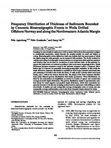
From the point of view of time and frequency dissemination, it is desirable to reproduce the time and frequency at any given location as precisely as possible referred to an adopted standard. There are two fundamental types of information that are transmitted via the active television system: 1) time interval that can be related to frequency, frequency being the inverse period of an oscillation, and 2) the date, or clock reading, that often has been called epoch. (We prefer the use of the word date because epoch has alternate meanings that could lead to confusion.) In principle, if one had perfect clocks, one could synchronize them once and they would remain synchronized forever. There are two basic reasons in practice why the synchronization does not persist. First, systematic (nonrandom) effects such as frequency drift, frequency offset, and environmental effects on equipment often cause time dispersion. These must be analyzed and each problem solved at a particular location. Secondly, there are different lqnds of random noise, or what 1) time of day as binary-coded decimal (BCD) logic that one might call nondeterministic kinds of processes, that affect can interface directly with a digital clock, these time and frequency systems. These latter processes can 2) 1-MHz standard frequency that exhibits good stability typically be classified statistically [SI. for use by broadcasters, industry, laboratories, or anyone wishing to obtain a frequency reference that is phase co111. THEACTIVE TELEVISION CODE herent with an NBS standard, Standard television broadcasts in the U. S. utilize a 525-line 3) time tick, 1 pps, which is an on-time pulse once each format to generate one video frame. The television screen is second to be used in conjunction with a time interval counter scanned from top to bottom twice to produce one frame by and remotely originated time tick. use of two interlaced fields (odd then even) of 262$ lines each. In order to implement the system on a nationwide scale, Referring to Fig. 1, we see that the vertical interval contains atomic frequency standards (primary and standby), along with no picture information. Unique sync pulses, which comprise
265
HOWE: TIME AND FREQUENCY DISTRIBUTION
HORIZONTAL I
I
F U L L W H I T E = 100 I R E PICTURE
6
VERTICAL INTERVAL
HORZ. EQUALIZING PULSES PULSES 3 s 0 s L,NI E-1
HORZ. PULSES t
/
VERTICAL PULSE 190.5 us
?u
~
PICTURE
LEADING EDGT
-
TRAILING 7 G E
-1
EQUALIZING PULSES
VERTICAL PULSES
EQUALIZING PULSES
t
HORIZ. PULSES
n m n n n n n n n -I