Navigation in Virtual Environments through Motor Imagery Robert Leeba , Reinhold Scherera , Felix Leeb , Horst Bischofb, Gert Pfurtschellera,c a Institute b Institute c Ludwig
of Human-Computer Interfaces, Graz University of Technology
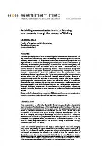
for Computer Graphics and Vision, Graz University of Technology
Boltzmann-Institute for Medical Informatics and Neuroinformatics, Graz University of Technology Inffeldgasse 16a, A-8010 Graz, Austria e-mail:
[email protected]
Abstract In this paper we report on the navigation in a virtual environment by the output signal of an EEG-based Brain-Computer Interface (BCI). Such a BCI transforms bioelectrical brain signals, modified by mental activity into a control signal. At this time only 1-D or 2-D BCI feedbacks are used. The graphical possibilities of virtual reality (VR) should help to improve BCI-feedback presentations and create new paradigms, with the intention to obtain a better control of the BCI. In this study the subjects had to imagine left or right hand movements and thereby exploring a virtual conference room. With a left hand motor imagery the subject turned in the room to the left and vice versa. Three trained subjects reached 77% to 100% classification accuracy in the course of the experimental sessions.
1 Introduction An electroencephalogram (EEG) based Brain-Computer Interface (BCI) is a communication system and represents a direct connection between the human brain and the computer. Mental activities or “thoughts” result in changes of electro-physiological brain signals. A BCI is able to detect and translate these changes into operative control signals. Imagination of movement effects similar neural networks in the brain as real execution of the same movement [7]. Therefore motor imagery is one important control strategy in BCI applications [10] and used to operate e.g. computer-controlled spelling devices (virtual keyboard) in patients with lockedin-syndrome [6] or neuroprosthesis in patients with spinal cord injury [8]. Patients suffering from amyotrophic lateral sclerosis (ALS) could reestablish a communication channel to their surrounding environment by controlling electric spelling devices [2]. The BCI developed in our group over the last decade, is based on the detection and classification of motor-imagery-related changes in the ongoing EEG [10]. The EEG data are classified in real-time and online feedback is given to the subject. During BCI experiments in the past
this feedback was either one-dimensional (1-D) or two-dimensional (2-D). Online feedback is given via a horizontal bar, whereby the length of the bar is equivalent to the classification output. So if a right hand movement is identified the bar goes to the right. Another feedback paradigm is the basket game, thereby the classifier output is used to modify the horizontal position of a down falling ball, so left hand imagery drops the ball into the left basket [5]. Of course all different kinds of feedbacks are possible, also selecting letters for writing or steering a prosthesis or a robot [11], but all of these feedbacks are simple visual presentations. In contrast, virtual reality (VR) is a powerful tool to generate three-dimensional (3-D) feedback with arbitrary adjustable complexity. The visualized picture can be a very simple and naked room, till a highly complex world, with textures added and animated moving objects [13]. In the presented work an EEG-based BCI is combined with VR as feedback medium. VR can provide dynamic and controllable experimental environments and is an optimally suited technology to create and design different types of realistic 3-D feedback. The combination of VR and BCI [1] opens up new possibilities for diagnostic and therapeutic arrangements. In this study the control signal from the BCI is used to navigate in a virtual environment (VE). At the moment only 2 classes are controllable, therefore only 2 directions of motions are possible. In the presented experiment the subjects had to explore the VE by turning left or right. This rotation was piloted by the imagination of a left or right hand movement. So a left motor imagery turned the subject to the left and vice versa.
2 Methods 2.1 Graz Brain-Computer Interface In the Graz-BCI the EEG is recorded over the sensorimotor cortex during the imagination of different types of movements (e.g. left or right hand movement), online processed, classified and transformed into a control signal [11]. In particular the event-related desynchronization (ERD) is used to convert brain states into control signals [10]. Characteristic spatial patterns can be found in the ERD depending on the preparation of the type of movement. This EEG phenomenon of the awake brain is characterized by a decrease in amplitudes (blocking, desynchronization) and corresponds to a state of higher cortical activity. While preparing to make a movement or imagining of such a movement, the ERD shows different spatial patterns depending on whether the left or right hand is involved. The ERD occurs contralateral prior to a real or during an imagined movement. This means that the preparation of or thinking on a right hand movement results in a power decrease over the left central hemisphere and vice versa. Imaginations of different movements result in characteristic spatial ERD patterns over the corresponding sensorimotor cortex [9]. The used BCI system consists of an EEG amplifier (g.tec, Austria), a data acquisition card (National Instruments) and a standard PC running WindowsXP (see Fig. 1). The raw EEG is recorded via two bipolar derivations, amplified, filtered and stored to hard disk. The recording and timing is handled via MATLAB 6.5 (MathWorks Inc., Natick, USA) in combination with Simulink 5.0 and Real-Time Workshop 5.0 [4].
VR Application
BCI Application
VRjuggler
SIMULINK
OpenGL
MATLAB
SGI Performer
Real-Time Kernel
Windows 2000
Windows XP
Hardware (incl. 3D card)
Hardware (incl. DAQ card)
PC System A (Rendering & Tracking)
3D Graphics Card
Left Eye
Right Eye
PC System B (Physiological Monitoring)
I/O
InertiaCube2 Tracking System
DAQ Card
Joystick Wand
keyboard
EEG amplifier
Virtual Research V8 HMD
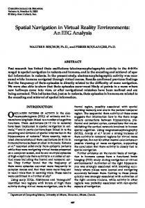
Figure 1: Block diagram of the BCI-VR system. The VR system on the left of the diagram gets input information from the tracking system, from a joystick and from a keyboard. Two stereoscopic images are calculated and sent to the HMD. The BCI system (right side) has the EEG as input and calculates a control signal. This signal is used to steer in the virtual environment. On the top of the diagram the software layers of both systems are displayed. The VR application layer has access to both VR Juggler and Performer. The real-time BCI application is running simultaneously on Simulink and MATLAB. The subjects are instructed to imagine a left or a right hand movement, depending on the trigger cue presented on a monitor. From scalp electrodes placed over the motor cortex, bipolar EEG channels are recorded and bandpass filtered between 0.5 and 30Hz. Artifacts, such as muscle and eye movements, were not discarded for online EEG analysis. The EEG is composed of different types of oscillatory activities, whereby oscillations in the alpha (8-12Hz) and in the beta (16-24Hz) band are particularly important to discriminate between different brain states. So a possibility to extract features from the EEG is to bandpass filter the EEG and then to calculate the logarithmic band power in the alpha and beta band. These features from all EEG channels are transformed with a linear discriminant analysis (LDA) between the two classes (e.g. left and right motor imagery) into a control signal.
2.2 Virtual reality system Many of the current and future VR experiments to be carried out in relation to the BCI require seated subjects to be placed in an immersive 3-D environment. Therefore, lower cost hardware system has been specified to cater for this scenario. A head mounted display (HMD) system
Brain-Computer Interface
Virtual Reality System
Signal Processing
Application
Navigation by thoughts
VR & OpenGL Framework
Tracker HMD Amplifier
V isual
Application Interface
Representation
EEG S ignals
EEG Acquisition
Electrodes
Figure 2: Schematic model of the combined framework with the BCI system on the left and the VR system on the right side. The BCI-PC sends extracted and classified EEG-parameters to the VR-PC and controls therewith the visual feedback (“navigation by thoughts”). The visual representation together with the BCI and the VR represents a closed loop system. was chosen, with the inclusion of a separate tracking system to monitor head movements in real-time. Rendering systems must be capable of real-time rendering of typical environments, delivering two separately rendered images to each stereo display (see Fig. 1). Low cost graphic cards targeted at the game industry are becoming capable of achieving this for professional and research use and have therefore been incorporated. A Virtual Research V8 HMD was chosen, with 640 x 480 pixels and a refresh rate of 60 Hz for both eyes. Because of the required EEG recording during VR experiments standard electro-magnetic tracking hardware was disregarded, due to the electrical sensitivity of the monitoring systems. Tracking techniques that would not affect the monitors include ultrasonic, vision and inertial systems. Due to the seated nature of the subjects and cost constraints, an InterSense InertiaCube2 3-DOF (degrees of freedom) system was chosen for use. This provides directional information (being rotational around the three primary axes) for the HMD using inertial integration methods, disregarding positional information. As VR software VR Juggler 1.0.6 and SGI Performer 3.0 were selected for use, running under Windows 2000 on a normal PC [14]. VR Juggler offers very basic, integrated support for existing rendering APIs, such as SGI OpenGL, SGI Performer, Open Inventor and Open Scene Graph. Therefore migrating of any developed or existing software components is possible. The practical link between the two systems is done via a modified keyboard (see Fig. 1). The BCI maps the classifier output via a digital I/O of the DAQ card on this modified keyboard and the resulting effect is the same as a user would press the appropriate button on the VR keyboard. With the BCI output signal the subject’s position in the VR system can be changed (see Fig. 2). So the subject sees a “thought-modified” picture of the VE.
Figure 3: Dual rendered picture of a virtual conference room with VR Juggler 1.0.6 and Performer 3.0 for stereo HMD usage.
3 Experiments and results 3.1 Subjects and experimental setup Four healthy subjects (age 26.2 ± 3.3) all familiar with the Graz-BCI were selected to participate in this study. Each volunteer was sitting in a relaxing chair and was instructed not to move. The subject was either sitting 150cm in front of a computer screen (standard BCI [11]) or was wearing a HMD. Two bipolar EEG channels (electrodes located 2.5 cm anterior and posterior to C3 and C4, respectively, according to the international 10-20 system) were recorded with a sampling frequency of 128 Hz and the band power (BP) was calculated sample-by-sample for 1-sec epochs in the alpha and beta bands. Two frequency bands selected from each EEG channel resulting in 4 BP features. Each subject was measured 4 times on different days (called sessions) and at each session one training and 3 feedback runs have been performed. The data of the training run were used to compute a LDA classifier and the error rates were calculated by a 10 times 10-fold cross-validation LDA-training. The estimated classifier with the best classification error during the feedback time (see Fig. 4) was selected for further usage in the feedback runs. In the feedback run the output of this classifier was used to control either the length and orientation of a horizontal bar or it was used as a rotation index within a virtual conference room (see Fig. 3). Training runs and bar feedback runs were performed using the computer screen. Only for the feedback runs within the virtual conference room the HMD was used. Depending on the affiliation of the cue, the subject was instructed to imagine a left or right hand movement. During the BCI bar feedback experiments, the feedback is given continuously during 5 seconds (see Fig. 4). The output of the classifier varies between -1 and 1, whereby negative numbers corresponds to the “left” class and positive numbers to the “right” one, respectively. The classification output is equivalent to the length of the bar during this kind of feedback. Using the same principle of presenting feedback in the conference room task would be, that the output of the classifier is directly mapped to the rotation angle, so negative classifiers results in left rotations (between 0◦ and 90◦ ) and positive in right ones. A varying view of the conference room is presented to the subject depending on this rotation angle. Modification of
cue beep
CUE
Fixation cross
0
1
2
Classifier
3
4
Feedback
5
6
Pause
7
8
time in s
Figure 4: Each run of the paradigm starts with a fixation cross, between second 3 and 4.25 the cue information as an arrow pointing to the left or right is superimposed onto this cross. Additionally a cue beep is given at second 3. In the case of feedback sessions the classifier output is presented till second 8. the rotation angle denotes that the field of view of the subject changes, thus the feeling should be as the subject is turning around itself. The LDA classification output is not very smooth and therefore classifier changes leads to strong modifications of the rotation angle. To avoid jumps of the rotation angle only the relative rotation information is used instead of an absolute one, thereby only the class affiliation is utilized, the value of the LDA is disregarded. So if the categorization was “left” the subject was rotating with constant speed at a predefined angle to the left or vice versa. The turning information is summed up over the time of the trial so a rotation by 90◦ to the left or right is possible. Additionally a small classification margin was introduced to make this feedback more suitable to the subject. If the output of the classifier was smaller than the defined margin, no movement in the VE happened. This “neutral zone” allowed the subject to have a smooth switch-over between the two turnings, so not abrupt change happened. The best threshold value of the margins for each class is estimated via ROC curves (Receiver Operating Characteristic) of the bar feedback run.
3.2 Timing of the paradigm Each trial lasted 8 seconds (see Fig. 4) and the time between two trials was randomized in a range from 0.5 to 2 seconds to avoid adaptation. The EEG was recorded continuously and stored on a hard disk. The experiment started with a fixation cross in the center of the monitor. Between second 3 and 4.25 an arrow was superimposed onto the cross and this cue stimulus pointed to the left or right. Simultaneous a cue tone was given. A low tone (700Hz) represented the left class and a high tone (1500Hz) the right one, respectively. Depending on the direction of the arrow, the subject was instructed to imagine a left or right hand movement. The additional class information via tone pitch was applied all the time to train and adapt the subjects to this kind of stimulus, because during the HMD experiments just the tone and no visual cue stimulus was featured. This solution was chosen, because it is not so easy to present the class information visually within the VE. Each session consisted of four experimental runs of 40 trials each (20 left and 20 right cues) and lasted about one hour. The sequence of right and left cues was randomized through each run.
b.)
1 0.8
right left
3 55%
3.5
50%
75%
65%
65%
58%
40%
0.6
4
50%
0.4
4.5
0.2
5
0
45%
−0.2
6.5 7
60%
68%
65%
75%
95%
70%
70%
83% 80%
90%
88% 80%
85% 80%
100%
7.5
100%
1
2
3
4
5
t[sec]
6
7
8
8
95%
−1
98%
95%
98%
90%
95%
85%
93%
85%
90%
−1 0
90%
95%
100%
−0.8
65%
63%
100%
−0.6
60%
55%
100%
−0.4
left
75%
85%
95%
6
right
80%
80%
85%
5.5
80%
75%
60%
time [sec]
LDA−Distance[−1