International Conference on Control, Automation and Systems 2007 Oct. 17-20, 2007 in COEX, Seoul, Korea
Navigation Strategy for the Service Robot in the Elevator Environment Jeong-Gwan Kang, Su-Yong An, and Se-Young Oh LG 302, P0STECH, San 31 Hyoja-dong, Namgu, Pohang, Korea1"2, 790-784 (Tel: +82-54-279-2880; E-mail: narool, grasshop,
[email protected])
Abstract: Recently, various service robot systems are introduced and offer the guidance and delivery service. However, most of them are operated on a single floor, because they do not consider the elevator environment. In this paper, we present the navigation strategy for multi-floor environment including elevator situation. Firstly, we propose the recognition method of the button and the floor number so that the robot reacts flexibly to a current elevator status. We apply adaptive threshold method to a current image in order to get a binary image and make the candidates of the button and the floor number using additional filtering method. By rejecting weak candidates using the artificial neural network, we finally get the position of button and current floor number. Secondly, we suggest the path planning algorithm for navigating in the elevator. By constructing an occupancy grid map of the inner part of the elevator, we calculate the optimal position to move and make a shortest path using the distance transform. Keywords: mobile robot, robot navigation, distance transform, path planning 1. INTRODUCTION Over the past years, the numbers of robots that have been deployed in museums, trade shows and exhibitions has been grown steadily and have offered much kind of services (guidance, delivery, cleaning, patrol, etc.) with high degrees of reliability. Most services that the robot offers are based on the autonomous navigation. So, the autonomous navigation is one of the most important fields in the intelligent mobile robot. The representative intelligent service robot is Minerva [1]. The Minerva were deployed in a museum during two weeks and offered the guidance service. Xavier [2] is the web-based autonomous robot. It estimates its location with the POMDP based localization algorithm and avoids the obstacle using the Lane-Curvature Method. The robot HERMES [3] has been demonstrated in a long-term test in a museum (both office and exhibition area) where it interacted and communicated with staff and visitors and actually performed useful services several hours a day for six months. In addition, many other service robots were introduced and they performed the autonomous navigation successfully in the museum or office environment. However, their autonomous navigation capabilities consider only the single-floor environment. So they are not able to navigate to the goal on another floor. To navigate in multi-floor environment, mobile robot should use an elevator. As a first step for moving to the other floor, the robot recognizes the up/down button of the elevator and presses it for calling. After calling the elevator, the robot continuously checks the indicator, which exists above the elevator door and shows a current moving direction of the elevator. If the moving direction of the elevator coincides with that of the robot, the robot gets in the elevator when the elevator door is opened. In the elevator, as second step, the robot stops in front of the operating panel and then presses the button of the
goal floor. Next, the robot moves to the center of the elevator and checks the current floor from indicator. Finally, if the elevator stops at the goal floor, the robot gets off the elevator. The GRACE [4] is able to detect and getting on/off the elevator using the laser scanner range sensor. However the GRACE cannot recognize where the elevator stops, because it does not have the number recognition algorithm. The MOPS [5] detects the state of the elevator doors using the LIDAR sensors and the manipulation of the elevator (selecting the floor, getting the floor information, etc.) is realized with the infrared communication system. Because of this, the MOPS is not able to get on/off the elevator which does not have the infrared communication system. For the robot using the elevator without other help, we first suggest the recognition method of the elevator status including the button, current floor and the moving direction. Then, we propose the navigation strategy especially path planning that enables the robot to get on/off the elevator safely. This paper is structured as follows. The next section present about the image processing algorithm for recognizing the button and number of the elevator and the third section presents the getting on/off method and localization method in the elevator. The last section presents the simulation and experiment results. 2. BUTTON AND NUMBER RECOGNITION For getting on/off the elevator, the robot should recognize the elevator status, which is consists of the button, current floor and the moving direction. Simply, let us call all these recognition targets 'object'. The four different objects that robot has to recognize are: - The up/down button at the outside of the elevator. - The current moving direction at the outside of the elevator.
978-89-950038-6-2-98560/07/$15©ICROS
1092
Extraction of horizontal & vertical line
Rotation angle
Segmented ROI
Raw Image
Adaptive Threshold
Recognition result
Connected component grouping
3D Position Extractor
Group analysis
Object recognition (Template matching Neural network)
ROI test (Neural network)
Extract object in ROI
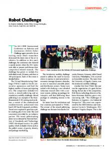
Fig. 1 The block diagram of the button and floor number recognition
(a) The simulation environment Pright Elevator door Pleft
(b) Raw laser points around the elevator door (a) the current moving direction at the outside of the elevator
(b) up/down button at the outside of the elevator
C2
C4
C3
C5
θ
P1,end door
C6
θ
L1 6
P1,start
(c) Clustering laser points (c) the floor button at the inside of the elevator
(d) the current floor at the inside of the elevator
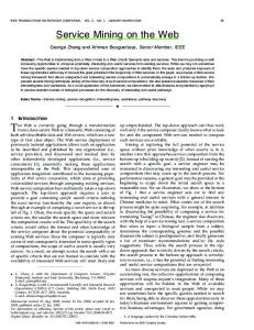
Fig. 2 The button and number recognition results - The floor button at the inside of the elevator. - The current floor at the inside of the elevator. In this paper, we propose the object recognition algorithm based on the adaptive threshold method and artificial neural network. The overall block diagram is shown in Fig. 1. 2.1 Extraction of Object Candidate All four objects get high pixel value in R channel of the image; therefore, pixel values of G and B channels are less important, so that we do not have to inspect all RGB value to recognize objects. By applying adaptive threshold to R channel of the color image and connected component grouping, we can extract the potential objects while removing non-objects and noise. In the next step, size filtering [8] is applied then we obtain reduced number of object candidates. Size filtering includes width to height ratio and minimum area test. 2.2 Object Recognition The objects of non-interest are rejected through neural network classifier, which is pre-trained by supervised learning. Training data consists of various object/non-object images. Template matching is applied to object candidate which satisfies neural network classifier. If the correlation between object candidate
Fig. 3 Detecting elevator door using laser scanner and template is lower than certain threshold value, then the object candidate is rejected as non-object. Correlation is given by
∑∑ T ( x′, y ′) ⋅ I ( x + x′, y + y ′)
R ( x, y ) =
x′
∑∑ x′
y′
y′
T ( x ′, y ′) 2 ⋅
∑∑ x′
(1)
I ( x + x ′, y + y ′) 2
y′
, where T and I are template and input image respectively. If same objects are recognized in the stereo image, then 3D position of recognized object is calculated using current robot position and object coordinate in image frame.
3. LOCALIZATION AND MAP BUILDING We make an occupancy grid map of the the elevator using laser scanner. In order to make the grid map, the robot should know its own position and it means that the map building also includes a localization problem. In this paper, the localization problem is solved using dead reckoning improved by an Extended Kalman Filter (EKF). 3.1 How to detect the elevator door The robot is positioned as shown in Fig 3(a), the system will see laser readings like those in Fig 3(b). For finding the position of the elevator door, Pright and
1093
Pleft , the algorithm that we developed is as follows : z Clustering the laser scan points z Finding the clusters which is longer than 0.5m z Finding the cluster pairs, Ci and Cj. The distance between end point of cluster Ci and start point Cj is within 1.4 ~ 1.6m z Finding the cluster pairs. Ci and Cj. The absolute value of the angle differences,
θi − θ j z
,
θ i − θ door
, θ j − θ door , have
to be lower than specific threshold Finding the position of the elevator. The end point of cluster, Ci ,is to be the right boundary of the elevator, Pright and the start point of cluster, Cj, is to be the left boundary of the elevator
3.2 Mobile robot localization using EKF We calculate the position of the robot using deadreckoning improved by EKF on the assumption that the robot has a map of the working environment and knows the position of the elevator door and wall. For compensating the deadreckoning error of the robot, the EKF is divided two steps: prediction step and correction step. In prediction step, the system estimates the position of the robot from the odometry data. In table 1, µ t is the position of the robot based on robot’s odometry and is calculated as follows: Table 1. The Extended Kalman filter algorithm 1
µ t = g (u t , µ t −1 )
3
Σt = GΣ t −1GtT + Rt
4
K t = Σt H tT ( H t ΣH tT + Qt ) −1
5
µ t = µ t + K t ( z t − h( µ t ))
7
where, vt =
matrix Σ t , which represent the uncertainty of the robot’s position. In correction step, we estimate the position of the feature points based on the predicted robot position and compare it to the feature points which are measured from the sensor. When the predicted robot position is µ t , the estimated feature position is calculated as follows:
(m − µ ) 2 + (m − µ ) 2 x t ,x y t, y h( µt ) = zˆt = − m µ y t ,y −1 tan ( m − µ ) − µt ,θ x t ,x
Where ( m x , m y ) are the coordinates of the feature point detection at time t. mx − µ t ,x − q ∂h ( µ t , m ) m y − µ t , y H= = ∂x t −1 q 0
− −
m y − µt, y q mx − µt , x q 0
0 (5) − 1 0
The matrix H is the jacobian matrix of measurement function h( µt ) , then, the kalman gain K is calculated in line 3. When, the position of feature point which measured from the sensor is given z t , the robot position and the uncertainty of the robot position are updated in line 5 and 6.
(2)
The matrix Gt is the jacobian matrix of g (ut , µ t −1 ) and the matrix R is the additional motion noise.
(4)
where, q = ( m x − µ t , x ) 2 + (m y − µ t , y ) 2
Σ t = ( I − K t H t ) Σt Return µ t , Σ t νˆt νˆt − ωˆ sin θ + ωˆ sin(θ + ωˆ t ∆t ) t t νˆt νˆt g (ut , µt −1 ) = µt −1 + cosθ − cos(θ + ωˆ t ∆t ) ωˆ t ωˆ t ωˆ t ∆t
vl + vr v −v , ωt = r l 2 2
Using the Gt and Rt, we can predict the covariance
Algorithm EKF( µ t −1 , Σ t −1 , u t , z t ):
2
6
vt vt 1 0 − ω cos + ω cos(θ + ∆θ ) t t (3) ∂g (ut , µ t −1 ) v v G= = 0 1 − t sin + t sin(θ + ∆θ ) ∂xt −1 ωt ωt 0 0 1
3.3 Map Building As mentioned above, we are using an occupancy grid map for riding the elevator. In mobile robotics, the occupancy grid is a two-dimensional tessellation of the environment into a grid G where each cell Cij holds a
part of environment information. The information can be of probabilistic or evidential character and is gathered with sensor (in our case laser scanner) mounted on the mobile robot. In most cases an occupancy grid is created by a mobile robot exploring the environment, updating the grid recursively while moving. Often the updated cell information is just a number that represents the belief that this part of the environment is occupied by an object or free. We use a
1094
Y
Cij Obstacle d left
d right
d bottom
X
(a) Elevator environment (b)Occupancy grid map
(a) Elevator environment
Fig. 4 The occupancy grid map in elevator
Bayesian approach in this work for the occupancy grid map building. The Bayesian approach relies on the Bayes rule: P ( B | Ai ) P ( Ai ) (6) P ( Ai | B ) = P( B ) For a grid map building purpose the event Ai plays the role of a cell being occupied or not. Each cell Cij of the grid map G is therefore associated with a binary random variable Sij with state (O)cupied or (E)mpty for which: (7) P ( Sij = O) + P ( Sij = E ) = 1
(b) 2D Fitness map of the elevator environment Y
Each cell Cij in the Bayesian grid map has a state probability pij associated and is initialized as follows: P( R | S ij = O ) pij (8) pij := P( R | Sij = O) pij + [1 − P( R | S ij = O)][1 − pij ] where P ( R | Sij = O ) represents the sensor model [7] .
4. PATH PLANNING
X
4.1 Fitness function In many cases, there are some passengers in the elevator and their positions can not be estimated before the elevator door open. Because of this, we are not able to decide to the robot’s stop position in the elevator. Thus, for find the stop position in the elevator, we calculate the fitness value from the occupancy grid map. Using Eqs. (9), (10), and (11), we select the optimal position G that has maximum fitness value to get in the elevator. (9) d min = min{d L , d R , d B } K3 K2 (10) f (i, j ) = K ⋅ d + d + d + + 1
min
L
R
(c) 2D Fitness map of the elevator environment Fig. 5 Calculation of the fitness in the grid map
d L − d R + 1 d B − offset + 1
G = arg max{ f (i, j )}
(11)
i, j
For arbitrary cell C ij in the occupancy grid map (Fig
Fig. 6 Distance transform result on elevator map
5(a)), the d L is the distance from C ij to the obstacle on the left side, the d R is distance to the obstacle on the right, and d B is distance to the bottom. Using Eq (10), we calculate the fitness value of each cell C ij . The cell C ij has a high fitness value when the
distance to the elevator door is close to offset value. So the cell G in Eq(11) corresponds to optimal position for robot stopping in the elevator and Fig 5 shows the fitness value for occupancy grid map of the elevator.
distance from C ij to other object is large and the
1095
(a) Fig. 7 Collision free path for getting in the elevator 4.2 Path Planning
To move to the goal which has the maximum fitness value in the fitness map, we make an optimal path using distance transform. The path planner considers the task of path planning to find paths from the goal location back to the start location. Fig 6 shows the distance transform results. Thus, for any starting point within the environment representing the initial position of the mobile robot, the shortest path to the goal is traced by walking down hill via the steepest descent path and Fig 7 represents the optimal path to goal.
(b)
5. EXPERIMENTAL RESULT The proposed method has been implemented on our mobile robot shown in Table 2. The robot used in experiment is an ActiveMedia PioneerDX2 mobile robot equipped with a HOKUYO URG-04LX laser range finder and two web cameras. For making human like appearance of the robot, we mounted a mannequin and put the clothes on. The experiment was carried out for several simulated and real environments. Fig 8 shows the robot’s
(c) Fig. 8 Collision free path for getting in the elevator
Table 2 Pioneer DX2 mobile robot used in experiments
•MORIS (MObile Robot for Intelligent Service) •HOKUYO laser range navigation
URG-04LX finder for
•Two web cameras for the number recognition
trajectory when the robot gets into the elevator in simulator environment. The robot can ride the elevator independent of the robot’s start position and the obstacle position in the elevator. (Fig 8(a), Fig 8(b)). Especially.
1096
Fig. 9 Experiment results in the Pohang City Hall
Fig 8(c) represent that the robot is not able to get in the elevator because of the obstacle. In this situation, the robot recognizes that getting in the elevator is impossible and return to the start position for waiting for the next elevator. Fig 9 shows that the robot gets in the elevator safe and moves to the goal floor in the real environment.
6. CONCLUSION In this paper, we propose the algorithm which makes the robot get in the elevator and move to the goal floor. First, the robot can check the state of the elevator using the number recognition algorithm based on adaptive threshold, thus our robot can decide get in or not, when the elevator door open. Second, we make the occupancy grid map about the inside of the elevator in real time. Using this occupancy grid map, we calculate the fitness for robot stop in the elevator and find optimal position for stop. Then, we calculate the path to the maximum fitness position. However, our robot does not have an arm, Because of this, the robot can not push the button for calling the elevator and can not use the elevator by itself. For the robot use the elevator without any help, we need more experiment about the pushing the elevator button using the robot arm.
[5] N. Tschichold-Gürman and S.J. Vestli, G. Schweitzer, “The service robot MOPS: First operating experiences,” Robotics and Autonomous Systems, vol. 34, pp. 165–173, 2001. [6] Teuvo Kohonen, “The Self-Organizing Map,” Proceedings of the IEEE, Vol. 78, No. 9, pp. 1464-1480, 1990. [7] A.Elfes, “Using Occupancy Grids for Mobile Robot Perception and Navigation,” Computer, Vol. 22, No. 6, 46-57, 1989. [8] Masahiro Tomono and Shin’ich Yuta, “Mobile Robot Navigation in Indoor Environments using Object and Character Recognition,” Proc. Of IEEE Int. Conf. Robotics and Automation, pp 313-320, 2000. [9] Se-Jin Lee, Jong-Hwan Lim and Dong-Woo Cho, “EKF Localization and Mapping by Using Consistent Sonar Feature with Given Minimum Landmarks,” SICE-ICASE International Joint Conference, pp 2606-2611, 2006. [10] Sebastian Thrun, Wolfram Burgard, and Dieter Fox, Probabilistic ROBOTICS, MIT Press, Cambridge, 2005.
ACKNOWLEDGEMENT This work was supported by grant No. RTI04-02-06 from the Regional Technology Innovation Program of the Ministry of Commerce, Industry and Energy (MOCIE)
REFERENCES [1] S. Thrun, M. Bennewitz, W.Burgard, A.B. Cremers, F.Dellaert, and D. Fox, “MINERVA: A Second-Generation Museum Tour-Guide Robot,” Proc. Of IEEE Int. Conf. Robotics and Automation, pp. 1999-2005, 1999. [2] R. Simmons, J. Fernandez, R. Goodwin, S. Koenig, and J. O’Sullivan, “Xavier: An Autonomous Mobile Robot on the Web,” Robotics and Automation Magazine, 1999. [3] Rainer Bischoff and Volker Graefe, “HERMES – a Versatile Personal Robotic Assistant,” Proceedings of the IEEE, Vol. 92, No. 11, pp. 1759- 1779, 2004. [4] Reid Simmons, Dani Goldberg, Adam Goode, Michael Montemerlo, Nicholas Roy, Brennan Sellner, Chris Urmson, Alan Schultz, Myriam Abramson, William Adams, Amin Atrash, Magda Bugajska, Michael Coblenz, Matt MacMahon, Dennis Perzanowski, Ian Horswill, Robert Zubek, David Kortenkamp, Bryn Wolfe, Tod Milam, and Bruce Maxwell, “Grace: An autonomous robot for the AAAI robot Challenge,” AAAI Magazine, vol. 42, No. 2, pp 51–72, 2003.
1097