PHYSICAL REVIEW E 79, 016602 共2009兲
Near-field probes using double and single negative media Muhammed S. Boybay* and Omar M. Ramahi† Electrical and Computer Engineering Department, University of Waterloo, 200 University Avenue West, Waterloo, Ontario, Canada N2L 3G1 共Received 3 July 2008; revised manuscript received 21 October 2008; published 8 January 2009兲 Evanescent probe imaging is a powerful characterization technique with subwavelength resolution. In this paper, we present a theoretical and numerical study of the effect of using double negative 共DNG兲 and single negative 共SNG兲 metamaterials in evanescent probe imaging. A sensitivity definition is introduced for evanescent probes and it is shown using quantitative measures that the sensitivity can be increased using DNG material for a target in vacuum and for a buried target. A minimum DNG thickness is required to achieve an improvement in the sensitivity. For a buried target, there is a fundamental limitation on the maximum achievable sensitivity, in addition to a limitation due to the loss of DNG materials. SNG metamaterials have similar improvements over the sensitivity as the DNG materials but there are additional limitations due to the different transmission characteristics of SNG media. To validate the theoretical findings, numerical simulations are presented. DOI: 10.1103/PhysRevE.79.016602
PACS number共s兲: 41.20.Jb, 81.70.Ex, 84.40.⫺x
I. INTRODUCTION
Evanescent field imaging is a powerful surface characterization technique and a promising technique for noninvasive subsurface imaging. The technique senses electrical and magnetic properties of materials with subwavelength resolution. Resolution values as low as / 106 关1兴 have been reported. The technique has been used on various materials, such as biological samples 关2兴, circuit boards 关3兴, or semiconductor samples 关4兴. A more recent application of the method for subsurface imaging focused on the detection of corrosion precursor pitting 关5兴. However, due to the fast decay of evanescent fields, the technique in Ref. 关5兴 was limited to detection of targets buried under a layer of thin paint. Since evanescent or near-field imaging has the capability to detect changes in the electrical and magnetic properties in materials, it is a strong candidate to detect biological anomalies or land mines. In Ref. 关6兴, it was shown that superresolution images can be constructed in half space problems if the evanescent field components are captured. For these diverse applications, the common challenge is the range and the sensitivity of the evanescent field probes. Recent developments in the double negative 共DNG兲 and single negative 共SNG兲 metamaterials offer a solution to these problems. By using the evanescent field amplification property, DNG or SNG based superlenses can be used to improve the sensitivity and range of the evanescent probe imaging methods. DNG materials have been attracting the attention of many scientists and engineers since the discovery of superlensing effect 关7兴 and the physical realization of DNG materials 关8兴. Theoretical field calculations in DNG materials and transmission through a DNG lens were reported in previous works 关7,9,10兴. In Ref. 关11兴, the superlensing effect was
*
[email protected] †
[email protected]; ⬃oramahi
URL:
1539-3755/2009/79共1兲/016602共10兲
http://www.ece.uwaterloo.ca/
combined with the nonlinear inverse scattering algorithms and was used for achieving subwavelength resolution images. Since DNG materials are dispersive and lossy, there are practical limitations on the superlensing effect 关12兴. The nature of DNG materials makes it impossible to have a perfect lens, whereas the superlensing effect, which refers to the subwavelength resolution capabilities of such lenses by evanescent field amplification, can be realized under less sever conditions. Numerical methods using the finite difference time domain 共FDTD兲 关13,14兴 and finite element methods 共FEM兲 关15,16兴 were implemented to simulate DNG materials. The evanescent field amplification and superlensing effect were demonstrated numerically. Experimental verifications of these extraordinary behaviors were achieved by using twodimensional circuit elements, loaded transmission lines 关17兴, and split ring resonator structures 关18,19兴 for DNG materials, and by using silver superlenses 关20兴 for SNG materials. Although the theory of the evanescent field imaging using DNG materials is well developed, its application to evanescent probe imaging has not been fully explored since the studies previously reported focused on detecting the evanescent spectrum emanating from an object 关7,21兴. An evanescent 共or near-field兲 probe, in essence operates by measuring the energy change in the surroundings of the probe tip. The objective of this work is to demonstrate how the DNG material affects the sensitivity of near-field probes. In Sec. II, independent of the probe media, we introduce a definition for sensitivity based on the electric and magnetic energy stored in the vicinity of the probe. In Sec. III, we present theoretical calculations of the sensitivity applied to a theoretical probe acting on multilayered media and targets, and show sensitivity enhancement when using DNG and SNG lenses. In Sec. IV, we present numerical simulation results for physically compact targets, thereby validating the theoretical calculations. Conclusions are presented in Sec. V.
016602-1
©2009 The American Physical Society
PHYSICAL REVIEW E 79, 016602 共2009兲
MUHAMMED S. BOYBAY AND OMAR M. RAMAHI
FIG. 2. The three components representing a generic probe: The resonator, the interface with the material to be interrogated 共the interface is represented here as a short transmission line兲, and the probe medium, which is a volume containing all the electric and magnetic energies excited by the resonator in the presence of the target medium.
R= FIG. 1. 共a兲 A generic probe is depicted by a cavity with a thin wire or tip coming out of it. 共b兲 The probe is modeled as a transmission line with a certain terminal impedance. 共c兲 A probe encountering a target is analogous to changing the terminal impedance of the transmission line, thus leading to a shift in S11.
冋 再冕
1 Re 兩Ii兩2
再冕
+ 4 Im
X=
冋 再冕
1 4 Re 兩Ii兩2
冎 冖 冎册 冎 再冕
共J* · E兲dv + 2
V
共S · n兲da
A
共uh − ue兲dv
V
共1兲
,
共uh − ue兲dv − Im
V
共J* · E兲dv
V
Evanescent probe detectors measure the evanescent field energy stored in the surrounding of the radiator tip. Any antenna, or any radiating system, can be modeled by a simple lumped circuit with passive elements if the system is linear. A load connected to a transmission line can be modeled as an impedance, Z = R + jX. The real part of the impedance, R, corresponds to the radiated propagating power and the loss of the system. The reactance X is related to the stored energy. Figure 1 shows a depiction of the probe 共which we assume here without loss of generalization as a cavity with a thin wire, or tip, extending out of it兲. A transmission line model of the probe is also shown in Fig. 1. Placing a target in the proximity of the probe is analogous to altering the terminal load of the transmission line, say from R + jX to R⬘ + jX⬘. A change in the terminal load would then affect the reflection coefficient, which is represented by the scattering parameter S11 关see Fig. 1共c兲兴. The change in the reflection coefficient 共frequency shift, magnitude shift, or both兲 reflects a change in the resonant frequency of the probe due to the presence of the target. Therefore a target can be detected easier if it leads to a higher change in the reactance. Since the change in reactance that the probe reacts to is in essence a distributed load, we consider the load to be the entire volume surrounding the tip of the probe, or more precisely, the entire volume where the field distribution is nonzero. Next, we express the resistance and the reactance of the terminal load in terms of the total fields described in Fig. 2. The resistance and the reactance can be expressed as 关22兴
,
共2兲
II. QUANTIFICATION OF SENSITIVITY A. Sensitivity
冎册
where J is the current density, E is the electric field, and uh and ue are the energy densities due to the magnetic and electric fields, respectively, in the volume V. S is the Poynting vector on the surface that encloses V and n is the normal vector of the surface pointing out of V as shown in Fig. 2. Ii is the current passing through the load Z. The first term of Eq. 共1兲 and the second term of Eq. 共2兲 are due to the conductive losses and they are equal to zero for a lossless medium. The 共uh − ue兲 difference is equal to zero for a propagating plane wave and it is purely real for an evanescent plane wave in a lossless medium. The second term in Eq. 共1兲 is the power radiated from the surface A and is negligible for near-field probes. For a propagating wave in a lossless medium Eq. 共1兲 reduces to the second term and Eq. 共2兲 is equal to zero. For an evanescent wave, however, the first term in Eq. 共2兲 is the only parameter that contributes to the impedance. Therefore the sensitivity can be defined as the deviation of the ratio of difference between total H and E field energies in the presence of the target to the total energy without the target as follows:
冏
Sensitivity = 1 − where Uh,e =
共Uh − Ue兲with
target
共Uh − Ue兲without
冕
uh,edv .
target
冏
,
共3兲
共4兲
V
According to the definition proposed in Eq. 共3兲, the deviation from zero, which can only take place if a target is present, is
016602-2
PHYSICAL REVIEW E 79, 016602 共2009兲
NEAR-FIELD PROBES USING DOUBLE AND SINGLE…
In most practical applications, such as the examples presented later in this paper, the target is not an infinite layer but rather localized in space. However, irrespective of the nature of the target, when it is interrogated with an evanescent field, a spectrum of traveling and evanescent plane waves is generated. In either case, whether the target is localized or not, an evanescent spectrum is generated. Therefore, it is purely for the purpose of developing a succinct mathematical theory for sensitivity enhancement that we consider the infinite layer target. Assuming a time-harmonic incident field in the left-hand half space in the form of E = yˆ e j共kxx+kz,1z兲 ,
FIG. 3. 共Color online兲 The probe and target interaction is modeled by a plane wave in a multilayered structure. The incident field is assumed to be excited at Z1, which represents the probe location. The last region is assumed to be an infinite half space.
a measure of higher sensitivity. From this sensitivity definition, it is not intuitive that the amplification of evanescent fields, as a consequence of using a superlens, would lead to increased probe sensitivity. This sensitivity definition 关i.e., Eq. 共3兲兴, as will be shown below, is not intended to quantify the sensitivity for specific targets but rather to be used as a tool or a measure to investigate the potential of near-field probes when used in conjunction with DNG media, SNG media, or, in fact, with any media in general.
共5兲
the field distribution can be found using the boundary conditions. On the mth boundary, the transmission and reflection coefficients are defined as tm and rm, respectively. The reflection and transmission coefficients for a multilayered structure can be found in Ref. 关24兴. We define evanescent plane waves using their k components parallel to the interfaces between the layers since this component does not change from one layer to another. When there is an incident wave with a parallel k component of kx and an E field polarized in the yˆ direction, the E and H fields become m−1
Em = yˆ 兿 tl共e jkz,mz + rme−jkz,mz兲,
共6兲
l=1
m−1
Hm = zˆ
kx 兿 tl共e jkz,mz + rme−jkz,mz兲 m l=1 m−1
B. Probe-target model using plane waves
Unlike earlier works where the near-field 共or evanescent field兲 probes were modeled using lumped elements, in this work, we present a field model for the probe-target interaction. This model is developed by using multilayer media as the target of detection and the material that it typically is embedded in. The energy coming from the resonator is represented as evanescent plane waves. Since all time-harmonic fields can be expressed as a superposition of plane waves 关23兴, the evanescent spectrum can be analyzed using the following formulation and the overall response of a probe is a combination of the responses of plane waves present in its spectrum. While, in theory, there is always small radiation coming out of the resonator used in near-field imaging, the magnitude of these propagating field components are small enough to warrant their exclusion from our model. In general, the target to be detected is embedded inside some target medium. Usually the target is electrically small and is of finite size. However, for the purpose of developing our probe-target model, we will consider a target that is of infinite size, i.e., a single layer, occupying the space Z3 ⬍ z ⬍ Z4, as shown in Fig. 3. Furthermore, the target can be backed by a multilayer medium. Therefore, in order to provide flexibility in the number of layers that correspond to the complexity of the structure, we calculate the fields for an arbitrary n number of boundaries. The coefficients are defined in a way that the solution can be calculated recursively.
− xˆ
kz,m 兿 tl共e jkz,mz − rme−jkz,mz兲 m l=1
共7兲
for 1 艋 m 艋 n, and for the last half space n
En+1 = yˆ 兿 tle jkz,mz ,
共8兲
l=1
n
Hn+1 =
共zˆkx − xˆkz,n兲 tle jkz,mz , 兿 n l=1
共9兲
where the dispersion relation is given as 2 kz,m = 2⑀mm − k2x .
共10兲
C. Near-field probe employing double negative media
DNG media has two primary features: First, it allows for phase propagation in the opposite direction to that of the direction of energy propagation 共k vector and Poynting vector S are 180° out of phase兲. The second important feature is the amplification of evanescent field magnitude. Both features have been used with much excitement in the past to reproduce the image of a source 关17,18,20兴. The second feature, namely, the amplification of evanescent fields, is clearly relevant to the field of near-field microscopy. What remains
016602-3
PHYSICAL REVIEW E 79, 016602 共2009兲
MUHAMMED S. BOYBAY AND OMAR M. RAMAHI
冏
„⑀共兲…
冏
= p/冑2
= 3⑀0 .
共15兲
Similarly, the derivative term in the H field energy density is equal to 30. If there are n number of boundaries, the total E field energy in the mth slab, defined by zm−1 艋 z 艋 zm, can be written as m−1
Ue,m =
t2l 兿 l=1
+ FIG. 4. 共Color online兲 A DNG slab is inserted between the target medium and the field excitation.
uncertain, however, is whether evanescent field enhancement translates into increased probe sensitivity in the sense defined in Eq. 共3兲. To this end, we consider the field solutions developed above, which are valid for propagating and evanescent plane waves. We insert a DNG medium between the probe tip and the target medium, as shown in Fig. 4. For a DNG layer, the sign of kz,m must be selected the opposite of the sign in the case of a positive medium 共for a good discussion on the compatibility between the mathematics and physics of DNG media, the reader is referred to Refs. 关9,10兴兲. The energy and sensitivity are calculated using field distributions. For the energy calculations, the DNG layer is represented as a dispersive medium. Thus, frequency dependence of permittivity of the DNG medium is assumed to be the same as the permittivity function of a metal around its plasma frequency, which is a commonly used model for DNG medium simulations. The frequency dependent permittivity and permeability are given as
冉
冊
2p ⑀共兲 = ⑀0 1 − , 共 − j⌫e兲
冉
共兲 = 0 1 −
冊
2p , 共 − j⌫m兲
where p is the plasma frequency and ⌫e and ⌫m represent the loss of the DNG medium 关25兴. For the lossless case, energy densities of the E and H fields for a linear medium can be found as 关22兴 ue =
1 „⑀共兲… 2 兩E兩 , 2
1 „共兲… 2 兩H兩 . uh = 2 p
共13兲
册
2 −2jkz,mzm−1 rm 共e − e−2jkz,mzm兲 . 4jkz,m
共16兲
Equation 共16兲 is valid for 1 艋 m 艋 n. Finally, for the last half space region, assuming a positive and nondispersive medium, the energy becomes n
Ue,n+1 = − 兿 t2l
⑀共n+1兲e2jkz,共n+1兲zn
l=1
4jkz,共n+1兲
共17兲
.
The energy due to the xˆ component of the H field is m−1
Uhx,m =
t2l 兿 l=1
+
冉 冊冋
„共兲… kz,m m
2
− rm共zm − zm−1兲
2 −2jkz,mzm−1 共e − e−2jkz,mzm兲 e2jkz,mzm − e2jkz,mzm−1 rm + 4jkz,m 4jkz,m
册
共18兲 for 1 艋 m 艋 n and n
Uhx,n+1 = − 兿 t2l l=1
冉 冊 kz,共n+1兲
2
e2jkz,共n+1兲zn . 4j共n+1兲kz,共n+1兲
共19兲
The energy due to the zˆ component of the H field is Uhz,m =
共11兲
共12兲
冋
e2jkz,mzm − e2jkz,mzm−1 共⑀共兲兲 rm共zm − zm−1兲 + 4jkz,m
冉
共共兲兲 „⑀共兲…
冊冉 冊 −1
kx m
2
Ue,m .
共20兲
For a lossy, dispersive medium, Eqs. 共13兲 and 共14兲 are not valid 关26兴. By simplifying the general solution presented in Ref. 关26兴 for a time-harmonic field in a Drude medium, the E field energy density can be found as
冉
冊
2 1 ue = ⑀0 1 + 2 p 2 兩E兩2 . 2 + ⌫e
共21兲
Therefore replacing the (⑀w共兲) term in Eq. 共16兲 by ⑀0共1 2p + 2+⌫ 2 兲 yields the energy equations that are compatible with e the lossy cases. Similarly, the H field energy density can be found as
冉
冊
2 1 uh = 0 1 + 2 p 2 兩H兩2 . 2 + ⌫m
共14兲
共22兲
III. THEORETICAL RESULTS
For a lossless plasma at = 冑2 the effective relative permittivity is equal to −1. Therefore
In this section, we calculate the sensitivity as defined in Eq. 共3兲 for different media and target configurations. We fo-
016602-4
PHYSICAL REVIEW E 79, 016602 共2009兲
NEAR-FIELD PROBES USING DOUBLE AND SINGLE…
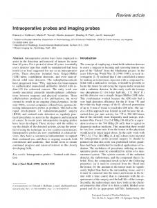
FIG. 5. 共Color online兲 Sensitivity as a function of lens-to-target distance, for DNG thicknesses of t, 2t, 3t, and 4t 共t = 0 / 75兲. As the DNG thickness is increased, the sensitivity increases. The nonmagnetic target is t thick with ⑀r of 6.
cus on the changes in the sensitivity as a result of using lossless and lossy DNG lenses, and then discuss the effect of using SNG lenses. A. Effect of a DNG lens without loss
In the first configuration to be analyzed, the target medium will be considered as a vacuum. The angular wave number of the material with the largest ⑀ product is defined as kmax. In order for the field to have evanescent behavior in all regions, the incident wave must have kx ⬎ kmax. Without loss of generality, we consider a nonmagnetic target with a thickness of t = 0 / 75, where 0 is the wavelength in free space, and a relative permittivity of 6. The input is an evanescent plane wave with a kx = 1.5kmax. The DNG lens is matched to the free space with relative permittivity and permeability equal to −1 since this amplifies the whole evanescent spectrum with a well-defined exponential function. The lens is assumed to be lossless. 共There is no reflection at the boundary between a DNG lens and a positive medium if they are matched.兲 Figure 5 shows the sensitivity for different DNG thicknesses. The sensitivity is plotted as a function of the lens-totarget distance, which is represented in terms of t. Throughout this paper, the lens-to-target distance is defined as the distance 兩Z3 − Z5兩 共see Fig. 4兲. Clearly seen is that the thicker the DNG lens, the higher the sensitivity; however, what is interesting is that there is a minimum DNG thickness required to achieve a sensitivity improvement. For example, as can be seen from Fig. 5, a DNG lens with a thickness of t does not improve the sensitivity. In fact, it turns out that a DNG thickness greater than 1.4t is needed for this particular configuration 共target thickness of t = 0 / 75 and ⑀r = 6兲. The reason for the minimum DNG thickness requirement can be explained as follows. When a target interacts with the evanescent field, there are two mechanisms that affect the E and H field energies. The first mechanism is due to the per-
FIG. 6. 共Color online兲 The H field and E field energy differences normalized by the difference without any target, 共Um−Ue兲with target 共Um−Ue兲without target , plotted as a function of the lens-to-target distance t. When there is no DNG layer the target reduces the difference. On the other hand, when there is a DNG layer the target increases the difference.
mittivity and permeability changes of the probe medium as a consequence of the presence of the target. For an evanescent TE wave in a dielectric medium, the difference of the E and H field energy densities can be calculated as uh − ue =
兩kz兩2 2 兩E兩 . 2
共23兲
As the permittivity is increased, 兩kz兩 is reduced to maintain a constant kx. From Eq. 共23兲, the reduction in 兩kz兩 leads to a reduction in the energy difference when there is a target with a higher permittivity compared to the surrounding medium. As a consequence, the second term in the sensitivity definition 关Eq. 共3兲兴 deviates further from unity. 共A similar conclusion applies when the target has a permittivity lower than the target medium.兲 The second mechanism is the energy change due to the reflection from the target. This mechanism increases the energy difference since it produces a reflected field with 兩uh − ue兩 greater than zero. When there is no DNG layer, the reflected field energies are small since the field is decaying and the dominant mechanism is the first mechanism. On the other hand, when there is a thick enough DNG layer, the reflected field is amplified and the second mechanism becomes more dominant. This behavior is presented in Fig. 6 共U −U 兲with target where the 共Umm−Ue兲ewithout ratio is plotted as a function of the target lens-to-target distance. Next, we consider the sensitivity behavior as a function of kx. Figure 7 shows that the sensitivity is improved for all kx values greater than unity, thus implying that the sensitivity improvement is valid for the entire evanescent spectrum. As a consequence, we make the key conclusion that the sensitivity improvement is valid for any type of near-field probes. For a subsurface detection scheme, a more realistic model would have a target medium other than vacuum. Here, we set
016602-5
PHYSICAL REVIEW E 79, 016602 共2009兲
MUHAMMED S. BOYBAY AND OMAR M. RAMAHI
FIG. 7. 共Color online兲 The sensitivity as a function of normalized kx. The inset shows that sensitivities of the fields with higher kx values experience better enhancements. Sensitivity improvement achieved by a DNG lens is defined as the sensitivity normalized by the sensitivity of the corresponding case without the DNG lens. The lens-to-target distance is 3t for all cases.
the relative permittivity of the target medium and the target to 2 and 6, respectively. The incident field is kept as before. The tip-to-lens and lens-to-target medium distances are kept at zero. All media, except the lens, are assumed to be nonmagnetic. In Fig. 8, the sensitivity versus the lens-to-target distance is plotted for different lens thicknesses, while keeping the thickness of the target constant at t. We observe that, in a manner similar to the target in the vacuum case, increasing the DNG thickness increases the sensitivity and a minimum DNG thickness is required to enhance the sensitivity. We further observe that the sensitivity is seen to be higher than the case when the target medium was a vacuum, since when
FIG. 9. 共Color online兲 The sensitivity behavior for a lossy DNG case. Sensitivity is plotted as a function of the lens-to-target distance for DNG thicknesses of 10t, 15t, 16t, 17t, and 21t. The target medium and the target have a relative permittivity of 2 and 6, respectively, and the target thickness is t. The DNG lens has an imaginary part of complex permittivity 共loss tangent兲 equal to 0.2.
the permittivity of the target medium is increased, the decay constant is reduced. Further analysis 共the graphs are not presented here for brevity兲 shows that although increasing the permittivity of the target medium increases the sensitivity, as the target medium permittivity approaches the permittivity of the target, the sensitivity is reduced. This is because even though the field penetrates better, it does not experience any significant change when encountering the target. An important behavior different than the case when the target medium is a vacuum is the saturation of the sensitivity improvement as the DNG lens thickness increases. For the configuration considered here, the sensitivity improvement is saturated when the thickness of the DNG lens reaches 20t, despite the lossless nature of the lens. Similar to the previous case 共target medium as a vacuum兲, the lens enhances the sensitivity for any incident evanescent field. Fields with higher kx have a higher enhancement potential when using a DNG lens, and increasing the target thickness or target-to-target medium mismatch increases the sensitivity.
B. Effect of a DNG lens with loss
FIG. 8. 共Color online兲 Sensitivity vs target depth for a buried target. The target medium has a relative permittivity of 2 and the target has a permittivity of 6 with a thickness of t. The sensitivity is plotted for five different lens thicknesses.
In practical applications, DNG materials are lossy. In the case of a lossy DNG lens, the sensitivity improvement is expected to be reduced and the loss will form an upper bound on the sensitivity enhancement whether the target medium is a vacuum or not. The loss effect is expected to be more dominant for high kx values. Since the amplification in the DNG lens is limited by the loss of the lens, and higher kx components need more amplification, these components suffer from loss. Figure 9 shows the sensitivity in the case of a lossy DNG
016602-6
PHYSICAL REVIEW E 79, 016602 共2009兲
NEAR-FIELD PROBES USING DOUBLE AND SINGLE…
FIG. 10. 共Color online兲 The transmission coefficient as a function of normalized kx is plotted for SNG and DNG lenses. Both lenses have a thickness of t. The SNG lens exhibits a singularity at kx = 121.3k0. The inset shows that before the singularity the SNG lens follows an amplification characteristic very similar to the DNG lens.
lens. The DNG lens parameters are p = 冑2.02 and ⌫e = 0.1, corresponding to a complex relative permittivity equal to −1 + j0.2. We observe that the sensitivity improvement is reduced compared to the case of a lossless DNG. In addition, there is an optimum DNG thickness needed to achieve maximum sensitivity. For instance, for the target and medium parameters considered here, the optimum thickness is around 15t. As the thickness is increased further, the sensitivity is degraded to lower levels, even lower than the case without the DNG lens, a consequence that is expected since a relatively thick DNG lens with loss shields the target from the source. C. SNG metamaterials
As DNG metamaterials, SNG metamaterials also amplify evanescent fields. There are additional fundamental limitations for the use of SNG metamaterials as compared to DNG metamaterials. The amplification characteristics of an SNG lens are different than a DNG matched lens. Firstly, a DNG lens amplifies both TE and TM waves, whereas an SNG lens amplifies either TM waves, if it is ⑀ negative, or TE waves, if it is negative 关7兴. Secondly, a DNG lens amplifies evanescent fields with an exponential behavior, meaning that the amplification of the field through a DNG lens increases exponentially with kx. An SNG lens, on the other hand, exhibits a singularity in the transmission behavior 关12兴, as shown in Fig. 10. The transmission behavior of an SNG lens can be analyzed in three regions within the kx domain. The first region is before the singularity where a behavior similar to the DNG layer is observed. The second region is around the singularity where the amplification is much higher in comparison to the amplification of the DNG lens. In the third region, after the singularity, the amplifica-
FIG. 11. 共Color online兲 Sensitivity vs target distance for a target medium and target having relative permittivity of 2 and 6, respectively, and a target thickness of t. The 5t SNG slab results in a sensitivity improvement similar to the DNG slabs. The 9.22t slab has a singularity when the target is at 1.5t. The 20t slab reduces the sensitivity.
tion decreases as kx of the incident field increases. As a result the SNG lens does not amplify the whole spectrum, but it has an upper kx limit after which the incident field is not amplified. The singularity behavior was also observed when the transmission was analyzed as a factor of the SNG lens thickness. In Fig. 11, the sensitivity as a function of lens-to-target distance is plotted for different SNG lens thicknesses. The incident field is a TE wave with kx = 1.5kmax. The SNG material has ⑀r = 1 and r = −1. The target medium and the target have a relative permittivity of 2 and 6, respectively, and the target thickness is t. For this configuration, the singularity is observed with an SNG lens of 9.22t thickness and a lens-totarget distance of 1.5t, as shown in the inset of Fig. 11. When the SNG lens is thinner than the singularity condition, the sensitivity improvement is similar to the DNG lens case. If the lens is thicker, the sensitivity improvement is reduced and increasing the thickness further eventually results in no sensitivity improvement in comparison to the case without the SNG lens. The SNG metamaterials have an advantage over the DNG metamaterials due to fabrication considerations. The DNG metamaterials are produced by using periodic split ring resonators for negative permeability, and periodic conductive rods for negative permittivity, simultaneously in a dielectric matrix 关8兴. The SNG metamaterials, however, need only either split ring resonators 关27兴 or conductive rods 关28兴, which reduces the fabrication complexity and the metallic content of the overall material. The drawbacks of the SNG metamaterials are the limitations over the evanescent spectrum, slab thickness, and its selectivity vis-a-vis TE and TM waves. On the other hand, the SNG metamaterial, due to the transmission singularity, has the potential for strong substantial improvement in the sensitivity.
016602-7
PHYSICAL REVIEW E 79, 016602 共2009兲
MUHAMMED S. BOYBAY AND OMAR M. RAMAHI
FIG. 12. 共Color online兲 The effect of the target on the E field distribution without 共a兲 and with 共b兲 a DNG layer. The upper panels show the field distributions when the lens-to-target distance is 40 / 5. The lower panels show the field distributions when the lens-to-target distance is 0 / 25. The rectangular waveguide has a side length of 0 / 5. The target thickness is 0 / 37.5 and the lens thickness is 0 / 5. IV. NUMERICAL RESULTS
In this section, we present numerical experiments where we consider two configurations in order to validate the theoretical findings of sensitivity enhancement discussed above. The numerical simulations are performed using HFSS, a three-dimensional finite element analysis tool by Ansoft corporation. In the first numerical experiment, we analyze the field change due to the presence of a DNG lens. We consider a cutoff waveguide with a rectangular cross section of dimensions 0 / 5 ⫻ 0 / 5. The field is excited from the left end of the waveguide as shown in Fig. 12. The E field distributions, with and without the DNG layer, are plotted along the waveguide for two different target locations. The generated field has a decay constant of 2.29k0. The amplifying region is a DNG lens matched to the free space with a loss tangent of −0.45. Figure 12共a兲 shows the E field distribution without any DNG layers. The target hardly changes the field distribution. The E field distribution with a DNG layer is shown in Fig. 12共b兲 where the field change in the DNG layer due to the target is visible. Therefore, it can be observed that the main role of the DNG lens is to enlarge the active region in which the field distribution is changed by the target. When there is no DNG lens, the target changes the fields only in the proximity of itself. On the other hand, as a result of the evanescent field amplification, when there is a DNG lens, the target also changes the field distribution in the lens itself. In the second experiment, we consider a probe consisting of an open-ended rectangular waveguide with a cross section of 7.11 mm⫻ 3.56 mm 共typically referred to as WR-28兲. This waveguide has been used as a near-field probe for detection of cracks on aluminum plates 关5兴. A schematic of the probe-target configuration is shown in Fig. 13. The image of a 1-mm-sided cubic crack is generated by sending a 30 GHz signal and analyzing the variation in the phase of the reflected signal. The waveguide is assumed to be semi-infinite so that the field reflected from the open end does not experience further reflections, preventing the multiple reflections in the waveguide. The waveguide is faced to an aluminum plate with a crack at the center. The probe is scanned over the aluminum surface and the phase of the reflection coeffi-
cient, S11, is recorded for each probe location. The standoff distance, defined as the distance from the waveguide 共or from the SNG layer, if there is any兲 to the aluminum plate, is 1 mm for all numerical experiments presented here. In order to analyze the effect of the evanescent field amplification on the imaging strength of the probe, SNG layers are placed immediately at the opening of the waveguide. The SNG lens has a relative permittivity equal to 1 and permeability equal to −1. If a lossless SNG material is used, spurious surface modes are excited. These modes are a result of the discretization used in the FEM procedure 关15兴. Therefore the lossless case cannot be analyzed using FEM. In Fig. 14 the phase shift due to a target at a position along the centerline of the waveguide is plotted as a function of the SNG layer thickness. The phase shift is defined as the difference between the reflection phase in the case of a plate with a crack at the center and the phase in the case of a plate without any crack. In this numerical experiment, the waveguide pointed to the center of the aluminum plate and the thickness of the SNG layer is changed. Increasing the SNG thickness results in a higher phase shift, which indicates a higher sensitivity. The phase shift is improved by 4.5 times when a SNG layer with a loss tangent of −0.2 and with an optimum thickness of 0.85 mm is employed. As the thickness exceeds the optimum thickness, sensitivity improve-
FIG. 13. 共Color online兲 Schematic showing a side view of the waveguide probe positioned on top of the aluminum plate having a crack. The SNG layer is positioned immediately at the opening of the waveguide.
016602-8
PHYSICAL REVIEW E 79, 016602 共2009兲
NEAR-FIELD PROBES USING DOUBLE AND SINGLE…
FIG. 14. 共Color online兲 The phase shift due to a target along the centerline of the waveguide as a function of the SNG layer thickness.
ment is degraded as predicted by the theory. Additionally, it was found that increasing the loss tangent of the SNG medium leads to a reduction in the sensitivity improvement. Once the optimum SNG thickness is found, the image of the crack is generated by using a 0.85 mm SNG lens. The improved image and the original image obtained without using any SNG lens are presented in Fig 15. The aluminum plate is placed in the xy plane and the waveguide is aligned parallel to the zˆ direction. Images are generated by recording the reflection phase while scanning the probe in the xy plane. The offset phase, which is defined as the reflection phase when there is no crack on the aluminum plate, is used to achieve the phase shift due to the crack. The images are extracted by mapping the phase shift due to the crack to the color maps shown in Fig. 15. The SNG layer produces a clearer image with a higher phase-shift peak. Note that the narrow side of the waveguide is along the xˆ direction 共see Fig. 13兲. Two important features are analyzed in the generated images: the sensitivity and the image quality. The sensitivity corresponds to the phase shift due to the target. The pre-
(a)
sented theoretical calculations in this work aim to analyze this sensitivity improvement. The sensitivity of the probe is the ultimate limitation on the detectability of the target. The second feature, the image quality, corresponds to the resolution of the imaging technique. The strength of the side lobes compared to the main lobe, and the size of the main lobe are the measures of the image quality. The image quality is crucial for differentiating two targets placed close to each other and the previously reported calculations aim to analyze the image quality of such a system 关7,11,18兴. Images presented in Fig. 15 confirm both sensitivity and image quality improvements. The images presented in Fig. 15 show that 1D images along the xˆ axis have sufficient information about the sensitivity improvement and the image quality. In order to reduce the computation time, 1D images are generated to further analyze the effect of the SNG thickness. Figure 16 shows 1D images for different SNG thicknesses. Above the optimum SNG thickness, the SNG layer degrades the sensitivity of the probe. In Fig. 16共d兲, the phase-shift peak due to the target is reduced to 0.37°. This value is half of the phase shift obtained without using the SNG layer.
V. CONCLUSION
In previous works, DNG and SNG media were found to amplify evanescent fields. The purpose of this work is to answer the question of whether these media can be used to enhance the effectiveness of near-field probes that work by detecting the change in the energy stored in the close proximity of the probe. In this paper, we presented a sensitivity definition, which can be used to study the effectiveness of DNG and SNG lenses in enhancing the sensitivity of nearfield probes. A model using multilayers for the probe-target interaction was introduced that allowed for the excitation of a single evanescent wave. It was found that by using DNG lenses, the sensitivity for buried and nonburied objects can be increased; however, the increase in sensitivity is not a monotonic function of the DNG lens thickness. In fact, it was found that the DNG thickness needed for increased sensitivity has a lower and upper bounds, irrespective of losses in the lens itself.
(b)
FIG. 15. 共Color online兲 The image of the 1 mm crack generated by scanning the waveguide in the xy plane: 共a兲 with an 0.85 mm SNG layer having −0.2 loss tangent and 共b兲 without an SNG layer. 016602-9
PHYSICAL REVIEW E 79, 016602 共2009兲
MUHAMMED S. BOYBAY AND OMAR M. RAMAHI
(a)
(b)
(c)
(d)
FIG. 16. 共Color online兲 The 1D images with 共a兲 0 mm, 共b兲 0.5 mm, 共c兲 0.85 mm, and 共d兲 1.4 mm SNG layers. All images are scaled with the same color map; black corresponds to −0.5° and white corresponds to 3.2°.
The effectiveness of SNG lenses was also discussed. The advantage of SNG media is its relatively easier fabrication in comparison to DNG media and the potential for a substantial increase in the sensitivity. The tradeoff is additional constraints on the sensitivity improvement. Finally, the theoretical findings presented in this work
关1兴 T. Wei, X. Xianga, W. Wallace-Freedman, and P. Schultz, Appl. Phys. Lett. 68, 3506 共1996兲. 关2兴 M. Tabib-Azar, J. L. Katz, and S. R. LeClair, IEEE Trans. Instrum. Meas. 48, 1111 共1999兲. 关3兴 M. Tabib-Azar, N. S. Shoemaker, and S. Harris, Meas. Sci. Technol. 4, 583 共1993兲. 关4兴 M. Tabib-Azar, P. S. Pathak, G. Ponchak, and S. LeClair, Rev. Sci. Instrum. 70, 2783 共1999兲. 关5兴 M. T. Ghasr, S. Kharkovsky, R. Zoughi, and R. Austin, IEEE Trans. Instrum. Meas. 54, 1497 共2005兲. 关6兴 T. J. Cui, W. C. Chew, X. X. Yin, and W. Hong, IEEE Trans. Antennas Propag. 52, 1398 共2004兲. 关7兴 J. B. Pendry, Phys. Rev. Lett. 85, 3966 共2000兲. 关8兴 R. A. Shelby, D. R. Smith, and S. Schultz, Science 292, 77 共2001兲. 关9兴 R. W. Ziolkowski and E. Heyman, Phys. Rev. E 64, 056625 共2001兲. 关10兴 R. W. Ziolkowski and A. D. Kipple, Phys. Rev. E 68, 026615 共2003兲. 关11兴 L. Zhao and T. J. Cui, Appl. Phys. Lett. 89, 141904 共2006兲. 关12兴 D. Smith, D. Schurig, M. Rosenbluth, S. Schultz, S. A. Ramakrishna, and J. Pendry, Appl. Phys. Lett. 82, 1506 共2003兲. 关13兴 X. S. Rao and C. K. Ong, Phys. Rev. B 68, 113103 共2003兲. 关14兴 N. Engheta and R. Ziolkowski, IEEE Trans. Microwave Theory Tech. 53, 1535 共2005兲. 关15兴 P. Kolinko and D. Smith, Opt. Express 11, 640 共2003兲.
were validated using two numerical experiments involving waveguides as probes. ACKNOWLEDGMENTS
This work was supported by Research in Motion and the National Science and Engineering Research Council of Canada under the RIM/NSERC Industrial Research Chair program.
关16兴 C. Caloz, C.-C. Chang, and T. Itoh, J. Appl. Phys. 90, 5483 共2001兲. 关17兴 A. Grbic and G. V. Eleftheriades, Phys. Rev. Lett. 92, 117403 共2004兲. 关18兴 K. Aydin, I. Bulu, and E. Ozbay, Appl. Phys. Lett. 90, 254102 共2007兲. 关19兴 J. D. Baena, L. Jelinek, R. Marques, and F. Medina, Phys. Rev. B 72, 075116 共2005兲. 关20兴 N. Fang, Z. Liu, T. Yen, and X. Zhang, Opt. Express 11, 682 共2003兲. 关21兴 N. Fang and X. Zhang, Appl. Phys. Lett. 82, 161 共2003兲. 关22兴 J. D. Jackson, Classical Electrodynamics 共John Wiley & Sons Inc., New York, NY, 1999兲. 关23兴 R. Harrington, Time-Harmonic Electromagnetic Fields 共McGraw-Hill, New York, NY, 1961兲. 关24兴 J. A. Kong, Electromagnetic Wave Theory 共John Wiley & Sons Inc., New York, NY, 1990兲. 关25兴 N. Engheta and R. Ziolkowski, Electromagnetic Metamaterials: Physics and Engineering Explorations 共John Wiley & Sons Inc., Hoboken, NJ, 2006, p. 10兲. 关26兴 T. J. Cui and J. A. Kong, Phys. Rev. B 70, 205106 共2004兲. 关27兴 J. Pendry, A. J. Holden, D. J. Robbins, and W. J. Stewart, IEEE Trans. Microwave Theory Tech. 47, 2075 共1999兲. 关28兴 J. B. Pendry, A. J. Holden, W. J. Stewart, and I. Youngs, Phys. Rev. Lett. 76, 4773 共1996兲.
016602-10