International Journal of Computer Networks & Communications (IJCNC) Vol.3, No.1, January 2011
NETWORK CODING-BASED CONGESTION CONTROL AT NETWORK LAYER: PROTOCOL DESIGN AND EVALUATION Zsuzsanna Ilona Kiss, Zsolt Alfred Polgar, Catalin Vinti, Mihaly Varga, Andrei Bogdan Rus, Virgil Dobrota Technical University of Cluj-Napoca, 28 Memorandumului St., 400114 Cluj-Napoca, Romania {Zsuzsanna.Kiss,Zsolt.Polgar,Mihaly.Varga,Bogdan.Rus, Virgil.Dobrota}@com.utcluj.ro,
[email protected]
ABSTRACT The paper proposes a congestion control protocol based on Network Coding (NC) operations for the butterfly topology. The proposed protocol defines XOR-based coding and decoding algorithms adapted to streams having different rates and characteristics, as well as a signalling protocol required for dynamic activation and deactivation of NC operations. Some general principles related to the integration of NC operations into data transmission protocols are also discussed. The congestion control protocol proposed was simulated in OMNeT++ and implemented in a real network to demonstrate its feasibility and to test the functioning of the proposed coding and signalling algorithm in different scenarios.
KEYWORDS Butterfly Topology, Congestion Control, Network Coding, Signalling Protocol, XOR-based Coding
1. INTRODUCTION Recent years have seen the networking community focused on rethinking the design and principles of the telecommunications networks. This is due to the current network architectures that allow innovations only in the applications, but in reality they require major changes of the whole philosophy. Two important aspects could be mentioned here. The first one is related to the problem of providing QoS and the second one refers to a scalable and fast reacting management. Quality of service demands the resource management, which is hard to be efficiently implemented in legacy networks, where independent data streams are transmitted separately. Fortunately in some scenarios, could be the use of NC techniques, in which case network nodes are employed not only to forward but also to process the incoming independent data streams. This approach is expected to have an important impact on content distribution, efficient flow control, network monitoring, resource sharing and security. From the management perspective the traditional paradigms have almost failed to scale and have reacted slowly to changing network conditions. Making the management an intrinsic part of the network is an important requirement of the future networks, being also an important requirement for providing better QoS. The fundamental concept of NC was first introduced at the turn of the millennium for satellite communication networks in [1] and later it was fully developed in [2], where the term “network coding” appeared firstly. The principle was further developed in [3], [4], where an algebraic description of linear NC was introduced and it was showed that this technique is an essential ingredient in achieving the capacity of the network. Random NC was introduced in [5] as a randomized coding method, which can be easier integrated in real networks. Furthermore [6] DOI : 10.5121/ijcnc.2011.3108
119
International Journal of Computer Networks & Communications (IJCNC) Vol.3, No.1, January 2011
showed that broadcast and multicast protocols perform better with NC in wired and wireless networks. Although the NC paradigm represents a relatively new domain, since the seminal paper presented by Ahlswede, it enjoys a rapid growth and an ever rising interest in information and coding theory, networking, wireless communications, complexity theory, cryptography. The advantages brought by these techniques, like improved throughput and reduced packet losses, are more and more exploited by telecommunication networks designers. The first practical implementation of NC techniques was described in [7]. This paper proposed the Avalanche system, which implemented network coding in peer-to-peer networks. The system was presented in July 2007 under the name of Microsoft Secure Content Downloader. NC can also take advantage to a large extent of the broadcast nature of the wireless medium. The COPE system based on XOR operation between packets was proposed in [8] and demonstrated that NC offers gains in terms of throughput and efficiency. Another successful story for data transmission in wireless networks was presented in [9], where an implementation method at the transport layer for the TCP/IP protocol stack was proposed. In [10], a wireless mesh testbed combines dedicated hardware (ORBIT platforms) with simulators (Click Router and/or NECO) [11]. The result is actually a packet-oriented peer-to-peer communication, simulating that throughput could be close to link capacity when latency is low. Another approach refers to multi-point to multi-point flow-oriented transmissions, where the synchronization aspects are delaying its deployment in practice. This is not a trivial task and theoretical solutions are proposed in [12]. Two clean-slate approaches, i.e. in-network management (INM) and generic path (GP), were introduced by FP7-4WARD project "Architecture and Design for the Future Internet". INM supposes inherent management (or at least integrated) into the monitored network, and not external as in the legacy solutions [13], while the generic path is an abstraction facilitating the development and integration of techniques enhancing the communication’s reliability and quality [14]. The combination of these two concepts in a common framework could create the environment allowing the large scale integration of NC techniques in the mentioned multi-point to multi-point transmissions. In this paper we propose a practical approach to network coding integration in wired networks in order to provide congestion control. It is proposed a protocol, named netCod protocol, running on the network nodes (routers) and implementing the coding and decoding procedures in the test topology (which is a butterfly network) and the signaling used for activating the coding mechanisms. The proposed protocol is acting at the network layer without noticeable modifications of the protocol stack and it exploits the possibility, in the packet switched network, for the headers to carry additional information in their fields. The main task of the netCod protocol is to perform switching between the non-coded and coded states of the network, based on traffic conditions, nodes capability to deliver additional data on some of their links and on the congestion state that might occur on the bottleneck link of the butterfly network. In the signaling process all nodes communicate with each other while the XOR-based coding is performed only by the central router, this being the only node where coding is required for a two-source and two-destination scheme, as shown in [15]. A somewhat similar protocol is proposed in [16], but integrated in the MPLS mechanism. The paper is organized as follows: Sections 2 discusses some general principles regarding the integration of NC techniques into communication protocols. Section 3 describes the congestion control protocol proposed (the netCod protocol) while Section 4 describes the implemented testbeds and discuses the results obtained by computer simulations and real measurements. Finally Section 5 concludes the paper.
120
International Journal of Computer Networks & Communications (IJCNC) Vol.3, No.1, January 2011
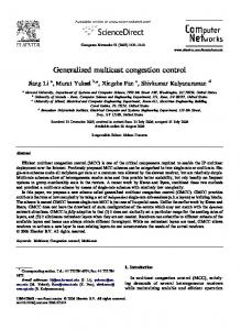
2. INTEGRATION OF NC TECHNIQUES INTO DATA COMMUNICATIONS NC represents a method to implement the cooperation between network nodes in order to perform congestion control. Cooperating nodes have to fulfil several conditions related to processing capabilities, synchronization and link characteristics which interconnect them each other. All nodes satisfying the given set of conditions form the coding network (or more generally a cooperation cluster). The employment of the NC techniques in practice requires a strong interaction between the appropriately defined data, control and management planes and the use of cross-layer techniques to provide the link statistics. Three principles can be identified for integration of NC techniques into data communications: a) Identification of the coding networks and instantiation in the nodes of these networks of software modules necessary for NC operation. Long term statistics acquired by the network management can be used to identify the network topologies where NC solutions exist and congestion level is large enough. The nodes and links of the mentioned topologies are marked as appropriate for NC operations, but these operations are initiated only when it is necessary. b) Dynamic NC application: link and flow characteristics have to be continuously monitored by the network management and the situations when the short and medium term statistics of congestion level and links transfer characteristics make NC viable solutions are identified by the control modules and the coding operations are activated. When, based on the mentioned statistics, is decided that NC is not a viable solution, the coding operations are deactivated. c) Dynamic flow encoding: theoretical studies of NC operations consider that coding operations are performed continuously. Due to the burstiness of real flows, data packets to be encoded are not present all the time in each node. On the other hand frequent activation/ deactivation of the NC operations are not acceptable due to the signalling overhead. The proposed solution is the following: once the NC operations are activated coding operations are performed only in the moments when data packets are available for encoding, otherwise non-coded packets are transmitted, as the decoding algorithm is able to discriminate them. The novelty of Figure 1 is related to the virtualization plane driven by cooperation techniques, i.e. the instantiation of NC-based cooperative data communications with QoS and with congestion control capabilities.
Figure 1. Network architecture where virtualization is based on cooperative communications The physical plane includes the physical network with all the nodes and transmission links interconnecting them. The cooperation-based virtual plane represents a virtual network 121
International Journal of Computer Networks & Communications (IJCNC) Vol.3, No.1, January 2011
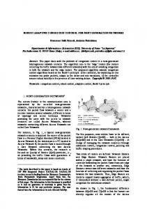
including all the NC-aware nodes with cooperation capabilities and the possible connections (i.e. abstract transmission links) between them. The cooperation clusters (coding networks) capable to implement congestion control are also identified. The operational plane represents the environment where data communications employing or not NC techniques are tacking place. The network management is capable to monitor the capabilities of nodes and transmission resources employing cross-layer techniques and to identify cooperation topologies. The control modules select the appropriate coding operations, activate/ deactivate the NC operations and control other related operations, like node synchronization. The complexity of the NC operations and associated processing (such as node synchronization) increases significantly whenever the number of nodes located within the cooperation cluster increases. A possible solution consists in splitting the cooperation plane in smaller cooperation networks/ clusters capable to control the congestions locally and allowing a simpler control of the coding operations. The well-known butterfly topology represented in Figure 2 is a popular solution investigated [2] [14].
Figure 2. XOR-based NC in the Butterfly topology By employing a simple XOR coding in the central node R5, and supplementary flows transmitted on the R1–R3 and R2–R4 links, it is possible to eliminate the effects of the congestion on the bottleneck link R5–R6. Even if the Butterfly topology is the simplest topology where NC can be employed, several problems have to be solved. They are related to flow synchronization, burstiness of the streams generating the congestion and activation/ deactivation of the coding process. The later operation is required to ensure efficient usage of the network resources. More exactly we refer to the resources required by the transmission of streams involved in the coding process on the R1–R3 and R2–R4 links. A modified encoding process is proposed to deal with the burstiness and different transfer rates of the source streams, as follows: •
Coding is performed only on the data packets which generates congestion at a given moment; if at a given moment no packets are transmitted in a stream the packets of the other stream are transmitted uncoded;
•
If the lengths of the packets which have to be encoded are not the same, only the common parts of the two packets are combined.
To perform this modified XOR encoding/ decoding operations the following structures of the source and of the encoded packets are proposed (see Figure 3): •
Flags - represent several bytes employed by the NC-based congestion control protocol; 122
International Journal of Computer Networks & Communications (IJCNC) Vol.3, No.1, January 2011
•
Sequence numbers or byte indexes - identify the source data which will be encoded.
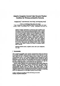
Figure 3. Frame structure for modified XOR-based NC operations Figure 4 presents an example where at least three butterfly topologies could be identified in a given network, each of them built around a bottleneck link and controlling locally the congestion on that link.
Figure 4. Overlapping butterfly topologies identified in a mesh network topology
3. THE NETCOD PROTOCOL The developed congestion control protocol, called netCod, is intended to control the activation/ deactivation of NC operations in a butterfly topology (see Figure 2) in order to control the congestion appearing on a bottleneck link connecting two NC capable nodes (the R5–R6 link in Figure 2). This is implemented at the network layer and it interacts closely with the IP operations. We suppose that the butterfly topologies built around the congested links are already identified by the network management. Furthermore, the routers implementing these topologies have supplementary capabilities, the functionalities of the network layer being extended. Note also that the links between the nodes of the butterfly topology could be generic ones composed of several links and nodes having no NC capabilities. The routers implementing the butterfly topology have the following extension of the IP functionality: it is defined the FlowTable module, storing the flow identifiers crossing the routers, and the netCod module (see Figure 5) was created and added within the network layer. This module implements the coding operations and the related control and signalling operations. The functionality of the IP was altered in the following way: if the coding operations are activated, all the packets are sent to the netCod module that implements the proposed control/ signalling and coding/ decoding operations. This module implements a set of processing steps through which the received packets are passing before being sent to the module 123
International Journal of Computer Networks & Communications (IJCNC) Vol.3, No.1, January 2011
implementing the IP protocol. This approach makes the netCod protocol a transparent add-on to the normal functionality of the network layer. The routers implementing the butterfly topology have different behaviour from the point of view of NC operations and the following classification is possible:
Figure 5. Graphical representation of the network layer with NC capability •
Routers R1 and R2 are defined as Butterfly Source Routers – BSR; they are sending uncoded information using multicast transmission (if the NC is ON) on the links connecting them with the other nodes of the topology; the netCod modules of these nodes have to monitor the output links and check if the rate conditions on these links are fulfilled for activation of the NC operations;
•
Router R5 is defined as Butterfly Coding Router – BCR; the FlowTable module is activated only within this router and it stores a set of parameters characterizing the streams that are crossing the node: the source and destination IP address, along with its corresponding transfer rate; the netCod module of this node permanently monitors the link to R6 in order to detect the congestion and when the network is in the coding state it encodes the streams passing through;
•
Router R6 is defined as Butterfly Bottleneck Router – BBR; it uses a multicast transmission for sending the coded packets to nodes R3 and R4;
•
Router R3 and R4 are defined as Butterfly Decoding Routers – BDR; in these nodes the netCod module performs the NC decoding operations.
The netCod protocol presented herein is composed of a congestion control mechanism with the associated signalling protocol and a coding mechanism designed to run on the network nodes. The communication between the nodes is based on two classes of messages: netCodControl and netCodData which are encapsulated in IP packets and sent across the network. The control packets have no payload and they are used in the signalling process, whilst data packets are used in the coding/ decoding process, having as payload either an IP datagram or the coding result. The structure of both packets types are detailed in Figure 8 and Figure 11.
3.1. The congestion control mechanism and the signalling protocol 3.1.1. Conditions necessary for NC activation Activation of the NC operations in the butterfly topology requires satisfying the following conditions: 124
International Journal of Computer Networks & Communications (IJCNC) Vol.3, No.1, January 2011
•
To have congestion on the link connecting nodes R5 (BCR) and R6 (BBR);
•
Instantaneous transfer rate on the output links of BSR routers have to fulfil the conditions: DR − R ≥ DR − R , D R − R ≥ DR − R 1 3 1 5 2 4 2 5
(1)
where Dx − y represents the rates of the streams involved in the NC operations. Note that links R1–R3 and R2–R4 are also used for transferring streams independent of the NC operations. Employment of instantaneous transfer rates for detection of the coding required conditions could be not a practical solution. Signalling related delays and limited measurement precision are the main drawbacks of utilization of the instantaneous transfer rates. On the other hand it is necessary to consider the interaction of the NC streams with other streams transmitted on the same physical links. Instead of using the instantaneous transfer rates in activation of the coding operations the following solution is proposed – we consider only the conditions related to the transfer rates on R1–R3 and R1–R4 links, the conditions related to transfer rates on links R2–R4 and R2–R3 being similar; see also Figure 6: •
Impose a maximum NC transfer rate Dmax on the R1–R5 link. This limitation is related to the processing time including the coding, decoding and the forwarding operations;
•
Compute/ measure the average NC transfer rate Dav on the R1–R5 link and acquire from network management the average available rate, Dav _ a1 on this link; acquire from network management the average available rate on the R1–R3 link Dav _ a 2 ;
Note: the available transfer rates on different links can be easily measured by the network management, not being necessary to identify the streams transmitted over the same link; on each link could be transmitted several streams involved or not in NC operations. •
To activate the coding it is necessary to fulfill the following conditions: Dav _ a1 ≥ thr1, Dav _ a 2 − Dav ≥ thr2
(2)
where thr1 and thr2 are positive values. The values of these thresholds depend on the burstiness of the streams transmitted on the R1–R4 and R1–R3 links; theoretically the threshold values could be zero, but if we want to account for the burstiness of the mentioned streams it is necessary to use threshold values larger than zero, reducing in this way the probability of the situations when the instantaneous conditions necessary for coding are not fulfilled. •
Coding is deactivated if the following conditions are not fulfilled: Dav _ a1 ≥ thr1, Dav _ a 2 ≥ thr3
(3)
where thr3 is a positive value; Detection of the congestion state on the R5–R6 link can be performed by the netCod module by computing the transfer rates (for an imposed time window) of the streams crossing R5 and comparing this value with the transfer rate of the physical link. Another solution is to detect the congestion state from the network management. Pre-congestion notification is also possible in both cases by analyzing the dynamics of the BCR’s input buffers.
125
International Journal of Computer Networks & Communications (IJCNC) Vol.3, No.1, January 2011
Figure 6. Transfer rate conditions imposed to BSR output links 3.1.2. The congestion control process The congestion control process has as goal in the particular case of the butterfly topology only the activation of the NC operations when congestion is detected on the bottleneck link and deactivation of the coding operations when the congestion is not present anymore. The control process is located in the netCod module of the BCR, which is a central node of this topology. BCR is the node who decides on the activation/ deactivation of the NC operations, based on local information and information acquired from other nodes through the signalling protocol. A flow chart of the congestion control process and the integration of this process in the communication tacking place between the sources and sinks are presented in the Figure 7. Three network states can be identified, namely: NORMAL, CODING and PENDING states, corresponding to legacy operation of the network, NC operations, and respectively to the signalling process of the network for NC activation. 3.1.3. The signalling protocol In order to switch between the classical routing and coding state, the nodes of the coding (cooperation) network must communicate using a signalling protocol and dedicated control packets. These packets have only header, the netCodControl header (see Figure 8), and no data field and are transported in IP packets. The proposed protocol is employing seven types of control packets defined by the TYPE field of the header: HELLO – used for neighbour discovery; it contains the router type (BSR, BCR, BBR or BDR) and it is sent by all routers. We assume that the role of each router has been assigned in a previous identification step of the butterfly topology, so the HELLO messages are needed just for acquiring the IP addresses of the neighbours. ACTIVATE – sent by BCR to BSRs and BBR as a request to activate the NC operations. If BSRs support the coding operations and the rate conditions on the BSR–BCR and BSR–BDR links are fulfilled, they send one copy of the control packet to the corresponding BDR. This signal is not activating effectively the NC operations. ACTIVATE_ACK – sent by the routers that previously receive an ACTIVATE request and support the activation. ACTIVATE_NACK – transmitted by the routers that already received an ACTIVATE request 126
International Journal of Computer Networks & Communications (IJCNC) Vol.3, No.1, January 2011
and for some reasons (e.g. cannot support additional traffic or perform coding/decoding) the coding operations could not be activated. ACTIVATE_NC – sent by BCR to all other routers (directly or indirectly) in order to effectively activate the NC operations. DEACTIVATE_NC – is a message sent by the BCR router when the shared link (R5–R6) is not congested anymore, or when NC operations could not be performed anymore due to some other reasons (e.g. node failure or rate conditions are not fulfilled in BSRs). This message effectively deactivates the coding operations. DEACTIVATE – is a message sent by any node of the topology (excepting BCR) to BCR requesting deactivation of the coding operations. The signalling operations employing the defined control packets are presented in Figure 9.
Figure 7. Flowchart of the NC based congestion control process When the coding network is identified by the network management the netCod and FlowTable modules are initialized in the cooperating nodes and each of these nodes sends a HELLO message to its neighbours, being acquired the addresses of these neighbours. The BCR router starts to monitor the R5–R6 link in order to detect congestions on this bottleneck link while the BSR routers monitor their output links checking if the rate conditions are fulfilled.
127
International Journal of Computer Networks & Communications (IJCNC) Vol.3, No.1, January 2011
Figure 8. The netCodControl header
Figure 9. Signalling messages exchanged between NC aware nodes If congestion is detected the BCR generates an ACTIVATE message which will be sent to all routers of the topology involved in cooperation. The routers which fulfil the conditions required by the NC operations generate an ACTIVATE_ACK message, while the routers which do not fulfil these conditions generate an ACTIVATE_NACK message. All these messages will be routed to the BCR, which will decide on the activation of NC operations. If all routers respond with an ACTIVATE_ACK message to the ACTIVATE request the BCR sends an ACTIVATE_NC message to all routers and the NC based congestion control operations begin. If congestion state is not detected anymore, the BCR sends a DEACTIVATE_NC message to all routers and NC operations are deactivated. If any other router detects that conditions required by NC operations are not fulfilled anymore it sends a DEACTIVATE message to the BCR router which will deactivate the NC operations in all routers using the DEACTIVATE_NC message. Because of continuous monitoring of the congestion and rate conditions, switching between the coding and normal states can lead to network malfunctioning. To overcome this issue and in order for the protocol to converge we introduced timers and a finite state machine, see Figure 10, based on the states described in Figure 7. Changing between the router’s states is determined by the type of message it received and it is conditioned by the timers also. We defined four 128
International Journal of Computer Networks & Communications (IJCNC) Vol.3, No.1, January 2011
types of timers: CONDITION_CONTROL – specifies the time interval for the congestion and rate condition to be tested by BCR respectively by BSRs; can take different values depending on the network characteristics and interaction between the data, management and control plane. ACTIVATION_TIMEOUT – if the activation acknowledgement did not arrive in this time interval to BCR, the activation is aborted. ACTIVATION_BLOCKED – specifies the minimum time interval the BCR router should wait before it will be able to make another attempt to activate coding (after one failed attempt). DEACTIVATION_BLOCKED – the minimum time interval that network should remain in the coding state (after it switched from NORMAL state).
Figure 10. Finite state machine of the NC aware routers
3.2. The coding and decoding operations At the time of activating the coding in the network, BCR (node R5) knows the streams that generated the congestion. This information is sent to BSR routers (R1 and R2, in the signalling process) in order that these streams to be labelled. Particularly, in this paper we have only two intersecting streams to generate the congestion and this signalling step could be avoided. When the network is in coding state, R1 and R2 attach the netCodData header to the IP datagram, belonging to one respectively to the other stream that must be coded. In this header they are writing an index in sequence No1 (see Figure 11) and filling in the flow field with 0 in R1 and with 1 in R2. The result is then encapsulated in an IP packet which is sent to R5 and R3, respectively to R5 and R4. For the destination router to know if the encapsulated packet represents a signalling or a data packet, the Protocol field from the IPv4 header is filled in with 200 for control or 201 for data (values chosen according to [21]). The ncDomain field is used to identify the coding network (cooperation cluster) where the congested link is located. In order to implement the coding mechanism the Butterfly Coding Router R5 has two buffers, one for each stream. Their purpose is to overcome the need of streams synchronization whenever the sources have different rates. The buffers storing timeouts should depend on the stream rate and they are carefully chosen because a mismatch between the packets arrival rate and the storing timeout could lead to a decreased efficiency of the NC operations. When a packet arrives to BCR and if there is no other one waiting to be coded (belonging to the other stream), the received data is stored into the corresponding buffer. If the storing timer expires, its netCodData header is stripped off and the packet is sent uncoded to destination. The coding technique is represented by bit-level XOR operation between two packets from two different streams, received from Butterfly Source Routers R1 and R2, as it was described in Section 2. The result of coding operation is encapsulated in a netCodData packet, where the 129
International Journal of Computer Networks & Communications (IJCNC) Vol.3, No.1, January 2011
index number of both packets is written in sequenceNo1 and sequenceNo2 fields. If the packets have different lengths, the shorter is padded with zero bits to match the maximum packet size.
Figure 11. The netCodData header At the decoding routers (i.e. nodes R3 and R4) arrive multicast packets from the BSR routers R1 and R2 and coded packets from BCR router R5. The decoding routers have two buffers, one for the multicast packets and one for the coded packets, needed for the alignment of the pair formed by one multicast and one coded packet. The alignment is necessary because the multicast packets are not synchronized with the coded ones and it is implemented using a storing timer for these two buffers. If the decoding router receives a multicast packet it reads its sequence number and the index of the stream it belongs to. Then the node will search in the buffer, where coded packets are stored, for the decoding pair, whose sequence number and stream index match with the read values. In case of no matching is found, the multicast packet will be stored in the corresponding buffer for a period of time specified by the storing timer. The same algorithm applies for the case when a coded packet arrives. Expiration of the storing timer denotes the fact that no decoding pair arrived in the specified time interval and the packet is dropped from the buffer, leading to one un-decoded packet.
4. EXPERIMENTAL RESULTS In order to test and evaluate the proposed congestion control protocol two testbeds were implemented which simulates respectively emulates the butterfly topology running NC operations. The reduced complexity of the butterfly topology allows a better testing of the developed protocol before large scale integration in more complex topologies. The first testbed simulates in OMNeT++ a butterfly topology, see Figure 12, consisting of 10 nodes connected by Ethernet links as follows: a) 2 server nodes that generate the traffic; b) 6 IPv4 routers [19] [20]; c) 2 client nodes that receive the decoded packets. Every network node is modelled in OMNeT++ by using a complex module composed by several basic ones, like the model presented in Figure 5. The servers and the clients operate up to the application layer. A UDP-based application runs on the servers S1 and S2 acting as traffic generator. The clients D1 and D2 are running also a UDP-based application that receives the generated traffic. The routers are connected by point-to-point links [22] having a maximum transfer rate of 100 Mbps. The congestion state on the link R5–R6 is checked every 5 seconds by BCR (node R5) by computing the total throughput of the streams that should be forwarded. If this exceeds the maximum capacity of the link, the switching process between the uncoded and coded states of the topology is started. The second testbed represents a real implementation of a butterfly topology composed of 6 computers (PCs) plus 4 PCs representing the server and client nodes. In this case the NC operations are implemented at the application layer and real time video streams are transmitted between the nodes of the topology using UDP transmissions. Network management modules are also implemented in each node of the butterfly topology in order to generate the link and congestion statistics necessary for the activation of the NC operations. 130
International Journal of Computer Networks & Communications (IJCNC) Vol.3, No.1, January 2011
Figure 12. The experimental butterfly topology
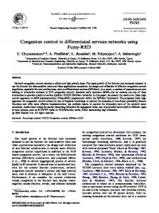
4.1. Simulation results Simulations were performed in three different scenarios, being analyzed the packet loss rate in coded respectively uncoded transmissions tacking place in the butterfly topology, respectively the dynamics of the coding and decoding operations according to the sizes of the buffers and storing timers used in BCR and BDRs. In the first scenario, two simulations of 60 seconds each were performed, with and without the netCod protocol instantiated in the network nodes. The traffic generated by the servers S1 and S2 has the transfer rate 80 Mbps, respectively 60 Mbps. The packet length varies with maximum 10% relatively to a reference packet length specified in the configuration file, so the generated traffic is varying within a range of ±10% relatively to the imposed transfer rates. During the network coding operations, the transfer rate on the bottleneck link is stabilized to the maximum of the two stream rates, while if coding is not employed the transfer rate of the R5–R6 bottleneck link reached its maximum value (about 90 Mbps). The buffer on BCR (node R5), corresponding to the stream with lower rate, generated by S2, is empty during the whole time when coding is on, the packets from this stream having always a coding pair and thus there is no need to store them. In the output stream of the BCR some packets are not coded. These packets are part of the stream with larger rate, generated by S1, and are packets for which the storing timer expired and no packets from the second stream have arrived. As a consequence, the coding operations are not performed (see Figure 13). All coded packets could be recovered at destination. In BDR, the size of the buffer where uncoded packets from BSR are temporarily saved depends on the storing timer and the rate of the stream generated by BSR. The decoding buffer where the coded packets are stored is usually empty, these packets arriving later than the uncoded ones. A comparison between the NC-aware and NC-unaware transmission, with respect to the number of bytes received by the sinks is presented in Figure 14. In the coded case almost all the data packets are decoded by the sinks, the lost packets being due to the limited storing time in the buffers located in BCR and BDR and to the fluctuations of the source streams rates. If the storing timers and buffer sizes are correctly set (see the discussion in the third scenario), the packet loss rate in congestion affected NC-aware transmissions can be significantly decreased. 131
International Journal of Computer Networks & Communications (IJCNC) Vol.3, No.1, January 2011 300000
277174
277174 277174
No. of packets
250000
Coded packets transmitted by R5
200000
Uncoded packets transmitted by R5
150000
Packets decoded by R3
94005
100000
Packets decoded by R4 50000 0
Figure 13. Decoded and uncoded packets relatively to coded packets 600000000
543920397
NC-aware
540941533
NC-unaware
No. of bytes
500000000
410151092 408000487 409780475
400000000 296909657 300000000 200000000 100000000 0 Sent by S1
Received by D2
Sent by S2
Received by D1
Figure 14. Number of bytes sent and received in the coded and uncoded case Within the second scenario it is evaluated the influence of sending asymmetric flows through the shared link on the dynamics of NC operations. The duration of the simulation was 20 seconds, the transfer rate of source S2 was 50 Mbps and the rate of source S1 was varied between 55 and 80 Mbps. As expected, if the difference between transfers rates increases, the number of the uncoded packets will increase also. This effect is depicted in Figure 15, but all the packets can be recovered if the storing timers are appropriately set. In the third scenario is verified the effect of the storing timers on the coding buffers sizes, the number of uncoded packets found in the decoding buffers and the overall performance. The simulation duration was 20 seconds, the transfer rate of source S1 was 80 Mbps and that of source S2 60 Mbps. The sizes of the coding and decoding buffers were set to 100 packets. The simulation results showed that the BCR’s buffer for the higher rate stream is full for the given buffer size and a storing timer of 18ms. Therefore the coding queue maximum size must be increased not to limit the performances of the NC. Note that the higher storing timer is, the lower the number of uncoded packets sent will be and the efficiency of the NC operations will increase. In the same time the storing timer has to be correlated with the size of the buffer in order to avoid packet drops. In Figure 16 it is presented the evolution of the number of uncoded packets according to the storing timer value and 100 packets size buffers.
132
International Journal of Computer Networks & Communications (IJCNC) Vol.3, No.1, January 2011
No. of uncoded packets
35000
33182
30000
28005
25000
22934
20000
15920
15000 10000
11109 4381
5000 0 5
10
15
20
25
30
Transfer rate difference between S1 and S2 [Mbps]
Figure 15. Uncoded packets sent by BCR vs. rate difference of the source streams 12000
Uncoded packets sent by R5
No. of packets
10000
8000
6000
4000
2000
29
27
25
23
21
19
17
15
13
11
9
7
5
0
Storing time for coding buffer [ms]
Figure 16. Number of uncoded packets for different storing timer values The performances of the NC operations are poor when the storing timers in BDR (nodes R3 and R4) exceed a certain value, because the storing buffers will be full and some packets will be dropped. For example, in the considered simulation scenario, when the timers are exceeding 9 respectively 13 ms, only a fraction of the number of bytes transmitted by S1 and S2 will be received by the sinks (see Figure 17 and Figure 18). This happens because of the high number of not decoded packets. Bytes sent by S1 Bytes received by D2
150000000
No. of bytes
145000000 140000000 135000000 130000000
29
27
25
23
21
19
17
15
13
11
9
7
5
125000000 Storing time for decoding buffer [ms]
Figure 17. Number of bytes received by D2 for different storing timer values in R4 133
International Journal of Computer Networks & Communications (IJCNC) Vol.3, No.1, January 2011 Bytes sent by S2 Bytes received by D1
160000000
No. of bytes
140000000 120000000 100000000 80000000 60000000 40000000 29
27
25
23
21
19
17
15
13
11
9
7
5
20000000 Storing time for decoding buffer [ms]
Figure 18. Number of bytes received by D1 for different storing timer values in R3 The value of the storing timer is related to the multicast rate required by the BDR to perform the decoding, but has to be correlated also with the size of the buffer. If the multicast rate is smaller the storing timer has to be larger but buffer overflow has to be avoided. In this scenario the multicast rate received by R3 (80 Mbps) is larger than the rate received by R4 (60 Mbps) and the storing timer in R3 has to be smaller (9 ms) than that in R4 (13 ms)
4.2. Real-time measurements The goal of the real time measurements is twofold: evaluate the performances of the NC operations in the situation of real traffic with imposed time constraints which is affecting the performances of the dynamic encoding and decoding operations; evaluate the dynamics of the developed signalling protocol in the situation of real network statistics acquired in real time. The source streams are represented by video streams having an average bit rate of 256 kbps. In Figure 19 – Figure 23 are presented the transfer rate distributions in time on different links of the butterfly topology when congestion is present or not on the bottleneck link and when NC is activated or not. R6 -> R4
Used Transfer Rate [bps]
600000 500000 400000 300000 200000 100000
1 7 13 19 25 31 37 43 49 55 61 67 73 79 85 91 97 103 109 115 121 127
0
Time [s]
Figure 19. Case 1 (no congestion): The shape of the transfer rate on link R6–R4 is similar to the original one on link R1–R5
134
International Journal of Computer Networks & Communications (IJCNC) Vol.3, No.1, January 2011
16 14 12 10 8 6 4 2 0
1 7 13 19 25 31 37 43 49 55 61 67 73 79 85 91 97 103 109 115 121 127 133 139 145
Available Transfer Rate [Mbps]
R5 -> R6
Time [s]
Figure 20. Case 2 (congestion, no NC-awareness): Available Transfer Rate on link R5–R6 determined by network management R6 -> R4
Used Transfer rate [bps]
600000 500000 400000 300000 200000 100000
1 7 13 19 25 31 37 43 49 55 61 67 73 79 85 91 97 103 109 115 121 127 133
0
Time [s]
Figure 21. Case 2 (congestion, no NC-awareness): The flow received by node R4 could not be used, as the packet loss rate was about 18%
7 6 5 4 3 2 1 0
1 6 11 16 21 26 31 36 41 46 51 56 61 66 71 76 81 86 91 96 101 106 111 116 121 126 131
Available Transfer Rate [Mbps]
R5 -> R6
Time [s]
Figure 22. Case 3 (congestion, NC-awareness): Available Transfer Rate on link R5–R6 determined by network management announced the congestion triggering NC operations 135
International Journal of Computer Networks & Communications (IJCNC) Vol.3, No.1, January 2011 R6 -> R4
Used Transfer Rate [bps]
600000 500000 400000 300000 200000 100000
1 7 13 19 25 31 37 43 49 55 61 67 73 79 85 91 97 103 109 115 121 127
0
Time [s]
Figure 23. Case 3 (congestion, NC-awareness): The used rate on link R6–R4 was close to the original, although the congestion remained; packet loss rate after decoding was about 0.75% The results obtained show, as it is expected, the possibility to deal with congestions by using NC, but the distribution of the transfer rates (the dynamics of these rates) will be affected. In the same time the packet losses (in congestion conditions) can not be completely eliminated due to the limited size decoding buffers and limited storing timers, but the packet loss probability is significantly reduced by coding. The signalling protocol described within Section 3 requires only minor changes (i.e. timer values) in order to work properly and to ensure the correct activation of NC operations.
5. CONCLUSIONS The paper proposes a congestion control protocol for the butterfly topology based on the employment of XOR-based Network Coding. It acts at the network layer and it is implemented by defining modules which extends the functionality of the IP protocol. The main task of the protocol is to activate the NC operations in the butterfly topology whenever the congestion is encountered in a bottleneck link and the conditions related to transfer rates are fulfilled on other links of the topology. The protocol deactivates the NC operations when congestion is not present anymore in order to release the supplementary resources required by the NC operations. The activation/ deactivation of the network coding are realized based on a signaling protocol integrated into the congestion control protocol. The coding and decoding operations were modified to accommodate rate and burstiness differences of the streams generating the congestion, allowing the integration of this mechanism in real traffic situations. Beside the concrete congestion protocol mentioned, the paper discusses also some basic principles related to the integration of the NC operation into data communication protocols. It is shown also that the proposed congestion control protocol dedicated for the particular butterfly topology could be extended to other more complex topologies by splitting them in elementary butterfly topologies. The developed congestion control protocol was evaluated by simulations realized in the OMNeT++ simulation environment and by tests realized in a real testbed, being demonstrated the feasibility and the functionality of the protocol. Based on the simulations and tests results some analysis concerning the performances and the dynamics of the NC operations in the condition of specified buffers sizes and storing timers values were performed.
ACKNOWLEDGEMENTS This work was supported in part by the FP7-ICT-2007-1-216041 “4WARD - Architecture and Design for the Future Internet” project and by the POSDRU/88/1.5/S/60078 grant “SIDOC Doctoral Studies in Engineering Sciences for Developing a Knowledge-Based Society”. 136
International Journal of Computer Networks & Communications (IJCNC) Vol.3, No.1, January 2011
REFERENCES [1]
Raymond W. Yeung & Zhen Zhang, (1999) “Distributed source coding for satellite communications”, IEEE Transactions on Information Theory, Vol. 45, No. 4, pp.1111-1120.
[2]
Rudolf Ahlswede, Ning Cai, Shuo-Yen Robert Li & Raymond W. Yeung, (2000) “Network information flow”, IEEE Transactions on Information Theory, Vol. 46, No. 4, pp. 1204–1216.
[3]
Ralf Koetter & Muriel Medard, (2003) “An algebraic approach to network coding”, IEEE/ACM Transactions on Networking, Vol. 11, No. 5, pp. 782–795.
[4]
Ralf Koetter & Muriel Medard, (2002) “Beyond routing: an algebraic approach to network coding”, Proceedings of the 21st Annual Joint Conference of the IEEE Computer and Communications Societies (INFOCOM 2002), Vol. 1, pp. 122-130.
[5]
Tracey Ho, Muriel Medard, Ralf Koetter, David R. Karger, Michelle Effros, Jun Shi & Ben Leong, (2006) “A random linear network coding approach to multicast”, IEEE Transactions on Information Theory, Vol. 52, No. 10, pp. 4413–4430.
[6]
Zunnun Narmawala & Sanjay Srivastava, (2008) “Survey of Applications of Network Coding in Wired and Wireless Networks”, Proceedings of the 14th National Conference on Communications (NCC 2008), pp. 153-157.
[7]
Christos Gkantsidis & Pablo Rodriguez, (2005) “Network Coding for Large Scale Content Distribution”, Proceedings of the 24th Annual Joint Conference of the IEEE Computer and Communications Societies (INFOCOM 2005), Vol. 4, pp. 2235-2245.
[8]
Sachin Katti, Hariharan Rahul, Wenjun Hu, Dina Katabi, Muriel Medard & Jon Crowcroft, (2006) “XORs in The Air: Practical Wireless Network Coding”, IEEE/ACM Transactions on Networking, Vol. 16, No. 3, pp. 497-510.
[9]
Jay Kumar Sundararajan, Devavrat Shah, Muriel Medard, Michael Mitzenmacher & Joao Barros, (2009) “Network coding meets TCP”, Proceedings of the 28th Annual Joint Conference of the IEEE Computer and Communications Societies (INFOCOM 2009), pp. 280-288.
[10]
Ioannis Broustis et al., (2009) “First Report on Test-Bed Functionalities and Implementation of Network Coding Schemes”, Deliverable 4.2, FP7-ICT-215252 N-CRAVE “Network Coding for Robust Architectures in Volatile Environments”, pp. 7-10, 24-26.
[11]
Diogo Ferreira, Luisa Lima & Joao Barros, (2009) “NECO: NEtwork COding Simulator”, Proceedings of the 2nd International Conference on Simulation Tools and Techniques (SIMUTools2009), pp. 52-68.
[12]
Thorsten Biermann, Martin Draxler & Holger Karl, (2009) “Flow Sychronization for Network Coding”, Academy Publisher Journal of Communications, Vol. 4, No. 11, pp. 873-884.
[13]
Giorgio Nunzi et al., (2009) “In-Network Management Concept”, Deliverable 4.2, FP7-ICT2007-1-216041-4WARD “Architecture and Design for the Future Internet”, http://www.4wardproject.eu/, pp. 39-42, 115-122.
[14]
Thorsten Biermann et al., (2009) “Description of Generic Path Mechanism”, Deliverable 5.2.0, FP7-ICT-2007-1-216041 4WARD “Architecture and Design for the Future Internet”, pp. 3-13.
[15]
Christina Fragouli & Emina Soljanin, (2006) “Information flow decomposition for network coding”, IEEE Transactions on Information Theory, Vol. 52, No. 3, pp. 829-848.
[16]
Thorsten Biermann, Arne Schwabe & Holger Karl, (2009) “Creating Butterflies in the Core – A Network Coding Extension for MPLS/RSVP-TE”, Proceedings of the 8th International IFIP-TC 6 Networking Conference, Lecture Notes In Computer Science, Vol. 5550, pp. 883-894.
[17]
Zaid Albanna et al., (2001) “IANA Guidelines for IPv4 Multicast Address Assignments”, Internet Engineering Task Force, RFC 3171.
[18]
Jon Postel et al., (1981), “Internet Protocol”, Internet Engineering Task Force, RFC 791.
[19]
Joyce Reynolds et al., (1994) “Assigned Number”, Internet Engineering Task Force, RFC 1700. 137
International Journal of Computer Networks & Communications (IJCNC) Vol.3, No.1, January 2011 [20]
William Simpson et al., (1994) “The Point-to-Point Protocol (PPP)”, Internet Engineering Task Force, RFC 1661.
Authors: Zsuzsanna Ilona Kiss received Dipl.Eng. degree and M.Sc. degree in Telecommunications Engineering from the Technical University of Cluj-Napoca in 2008 and 2010, respectively. Currently she is a Ph.D. student at the above mentioned university. Her research interest involves cooperative communications and network coding.
Zsolt Alfréd Polgár received Dipl.Eng. degree, M.Sc. and Ph.D. degrees in Telecommunications Engineering from the Technical University of Cluj-Napoca in 1995, 1996 and 2002, respectively. Since 1996 he is with the Communication Department of Technical University of Cluj-Napoca, where currently he is Associate Professor. His research interests involve error correcting codes, wireless networks, network coding and cooperative communications.
Catalin Vinti graduated in 2009 at TU Cluj-Napoca, holding Dipl.Eng. in Telecommunications. Currently he is M.Sc. student in the same area, being interested in network coding and quality of experience in video communications.
Mihály Varga holds the Dipl.Eng. degree, M.Sc. and Ph.D. degrees in Telecommunications Engineering received from the Technical University of Cluj Napoca. Currently he is a Senior Lecturer at the Communication Department of the mentioned university. His research interests involve error correcting codes, cooperative communications, wireless networks.
Andrei Bogdan Rus received Dipl.Eng. in Telecommunications (2007) and M.Sc. in Telecommunications (2009) at TU of Cluj Napoca. Currently he is Ph.D. student working for a thesis related to cross-layer QoS. Andrei Bogdan was involved in COST 290 and FP7-4WARD.
Virgil Dobrota holds Dipl.Eng. in Telecommunications (1987) and Ph.D. in Electronics and Telecommunications (1995) from Technical University of Cluj-Napoca. He is currently professor at TU Cluj-Napoca and Head of Communications Department, teaching switching and routing systems, Internet protocols and unified communications. Professor Dobrota was involved in RACE-MAGIC, INCO-COPERNICUS 1529, ACTS AC235, COST 290, FP7-4WARD. Member of IEEE Communications Society, ACMSIGCOMM, he served as TPC Co-Chair at IEEE LANMAN 2007 and General Co-Chair at IEEE LANMAN 2008.
138