GFD-R-P.206 NML-WG
[email protected]
Jeroen van der Ham, UvA (editor) Freek Dijkstra, SURFsara Roman Łapacz, PSNC Jason Zurawski, Internet2 May 2013
Network Markup Language Base Schema version 1 Status of This Document Grid Final Draft (GFD), Proposed Recommendation (R-P).
Copyright Notice c Open Grid Forum (2008-2013). Some Rights Reserved. Distribution is unlimCopyright ited.
Abstract This document describes a set of normative schemas which allow the description of computer network topologies.
Contents Abstract . . . . . . . . . . . . . . . Contents . . . . . . . . . . . . . . . 1 Introduction . . . . . . . . . . . 1.1 Context . . . . . . . . . . . 1.2 Scope . . . . . . . . . . . . 1.3 Notational Conventions . . 1.4 Diagrammatic Conventions 2 NML Base Schema . . . . . . . 2.1 Classes . . . . . . . . . . . 2.1.1 Network Object . . 2.1.2 Node . . . . . . . . 2.1.3 Port . . . . . . . . 2.1.4 Link . . . . . . . .
. . . . . . . . . . . . .
. . . . . . . . . . . . .
. . . . . . . . . . . . .
. . . . . . . . . . . . .
. . . . . . . . . . . . .
. . . . . . . . . . . . .
. . . . . . . . . . . . .
. . . . . . . . . . . . .
. . . . . . . . . . . . .
. . . . . . . . . . . . .
. . . . . . . . . . . . .
. . . . . . . . . . . . .
. . . . . . . . . . . . .
. . . . . . . . . . . . .
. . . . . . . . . . . . .
. . . . . . . . . . . . .
. . . . . . . . . . . . .
. . . . . . . . . . . . .
. . . . . . . . . . . . .
. . . . . . . . . . . . .
. . . . . . . . . . . . .
. . . . . . . . . . . . .
. . . . . . . . . . . . .
. . . . . . . . . . . . .
. . . . . . . . . . . . .
. . . . . . . . . . . . .
. . . . . . . . . . . . .
. . . . . . . . . . . . .
1 1 4 4 4 5 5 6 6 7 8 9 9 1
GFD-R-P.206
2.2
2.3
2.1.5 Service . . . . . . . . 2.1.6 Switching Service . . 2.1.7 Adaptation Service . . 2.1.8 De-adaptation Service 2.1.9 Group . . . . . . . . 2.1.10 Topology . . . . . . . 2.1.11 Port Group . . . . . . 2.1.12 Link Group . . . . . . 2.1.13 Bidirectional Port . . 2.1.14 Bidirectional Link . . 2.1.15 Location . . . . . . . 2.1.16 Lifetime . . . . . . . 2.1.17 Label . . . . . . . . . 2.1.18 Label Group . . . . . 2.1.19 Ordered List . . . . . 2.1.20 List Item . . . . . . . Relations . . . . . . . . . . . 2.2.1 canProvidePort . . . . 2.2.2 existsDuring . . . . . 2.2.3 hasInboundPort . . . 2.2.4 hasLabel . . . . . . . 2.2.5 hasLabelGroup . . . . 2.2.6 hasLink . . . . . . . . 2.2.7 hasNode . . . . . . . 2.2.8 hasOutboundPort . . 2.2.9 hasPort . . . . . . . . 2.2.10 hasService . . . . . . 2.2.11 hasTopology . . . . . 2.2.12 implementedBy . . . 2.2.13 isAlias . . . . . . . . 2.2.14 isSerialCompoundLink 2.2.15 isSink . . . . . . . . . 2.2.16 isSource . . . . . . . 2.2.17 item . . . . . . . . . 2.2.18 locatedAt . . . . . . . 2.2.19 next . . . . . . . . . 2.2.20 providesLink . . . . . 2.2.21 providesPort . . . . . Attributes . . . . . . . . . .
May 2013 . . . . . . . . . . . . . . . . . . . . . . . . . . . . . . . . . . . . . . .
. . . . . . . . . . . . . . . . . . . . . . . . . . . . . . . . . . . . . . .
. . . . . . . . . . . . . . . . . . . . . . . . . . . . . . . . . . . . . . .
. . . . . . . . . . . . . . . . . . . . . . . . . . . . . . . . . . . . . . .
. . . . . . . . . . . . . . . . . . . . . . . . . . . . . . . . . . . . . . .
. . . . . . . . . . . . . . . . . . . . . . . . . . . . . . . . . . . . . . .
. . . . . . . . . . . . . . . . . . . . . . . . . . . . . . . . . . . . . . .
. . . . . . . . . . . . . . . . . . . . . . . . . . . . . . . . . . . . . . .
. . . . . . . . . . . . . . . . . . . . . . . . . . . . . . . . . . . . . . .
. . . . . . . . . . . . . . . . . . . . . . . . . . . . . . . . . . . . . . .
. . . . . . . . . . . . . . . . . . . . . . . . . . . . . . . . . . . . . . .
. . . . . . . . . . . . . . . . . . . . . . . . . . . . . . . . . . . . . . .
. . . . . . . . . . . . . . . . . . . . . . . . . . . . . . . . . . . . . . .
. . . . . . . . . . . . . . . . . . . . . . . . . . . . . . . . . . . . . . .
. . . . . . . . . . . . . . . . . . . . . . . . . . . . . . . . . . . . . . .
. . . . . . . . . . . . . . . . . . . . . . . . . . . . . . . . . . . . . . .
. . . . . . . . . . . . . . . . . . . . . . . . . . . . . . . . . . . . . . .
. . . . . . . . . . . . . . . . . . . . . . . . . . . . . . . . . . . . . . .
. . . . . . . . . . . . . . . . . . . . . . . . . . . . . . . . . . . . . . .
. . . . . . . . . . . . . . . . . . . . . . . . . . . . . . . . . . . . . . .
. . . . . . . . . . . . . . . . . . . . . . . . . . . . . . . . . . . . . . .
. . . . . . . . . . . . . . . . . . . . . . . . . . . . . . . . . . . . . . .
. . . . . . . . . . . . . . . . . . . . . . . . . . . . . . . . . . . . . . .
. . . . . . . . . . . . . . . . . . . . . . . . . . . . . . . . . . . . . . .
. . . . . . . . . . . . . . . . . . . . . . . . . . . . . . . . . . . . . . .
. . . . . . . . . . . . . . . . . . . . . . . . . . . . . . . . . . . . . . .
. . . . . . . . . . . . . . . . . . . . . . . . . . . . . . . . . . . . . . .
10 11 11 12 13 13 14 15 15 16 16 17 18 18 18 18 19 19 20 20 21 21 22 22 22 23 24 25 25 25 25 26 26 27 27 27 27 28 28 2
GFD-R-P.206 2.4 Parameters . . . . . . . . . . . . . . . . . . . 3 Identifiers . . . . . . . . . . . . . . . . . . . . . . 3.1 Schema Identifier . . . . . . . . . . . . . . . . 3.2 Instance Identifiers . . . . . . . . . . . . . . . 3.2.1 Lexical Equivalence . . . . . . . . . . 3.2.2 Further Restrictions . . . . . . . . . . 3.2.3 Interpreting Identifiers . . . . . . . . . 3.2.4 Network Object Attribute Change . . . 3.3 Unnamed Objects . . . . . . . . . . . . . . . 4 Syntax . . . . . . . . . . . . . . . . . . . . . . . . 4.1 XML Syntax . . . . . . . . . . . . . . . . . . 4.2 OWL RDF/XML Syntax . . . . . . . . . . . . 4.3 Combining Object Descriptions . . . . . . . . 4.4 Ordered Lists . . . . . . . . . . . . . . . . . . 5 Examples . . . . . . . . . . . . . . . . . . . . . . . 5.1 Examples in XML . . . . . . . . . . . . . . . 5.2 Examples in OWL . . . . . . . . . . . . . . . 5.3 Conceptual Examples . . . . . . . . . . . . . 5.3.1 Topology and Node . . . . . . . . . . 5.3.2 Hierarchical Topology . . . . . . . . . 5.3.3 Links, Segments and Paths . . . . . . 5.3.4 Patch Panel and Media Convertor . . . 5.3.5 VLAN and Broadcast Medium . . . . . 5.3.6 Configuration and Potential Capability 5.3.7 Versioning and Lifetime . . . . . . . . 6 Security Considerations . . . . . . . . . . . . . . . 7 Contributors . . . . . . . . . . . . . . . . . . . . . 8 Acknowledgments . . . . . . . . . . . . . . . . . . 9 Intellectual Property Statement . . . . . . . . . . . 10 Disclaimer . . . . . . . . . . . . . . . . . . . . . . 11 Full Copyright Notice . . . . . . . . . . . . . . . . Appendix A XML Schema . . . . . . . . . . . . . . . Appendix B OWL Schema . . . . . . . . . . . . . . . Appendix C Relation to G.800 . . . . . . . . . . . . . References . . . . . . . . . . . . . . . . . . . . . . . . Normative References . . . . . . . . . . . . . . . . Informative References . . . . . . . . . . . . . . . .
May 2013 . . . . . . . . . . . . . . . . . . . . . . . . . . . . . . . . . . . . .
. . . . . . . . . . . . . . . . . . . . . . . . . . . . . . . . . . . . .
. . . . . . . . . . . . . . . . . . . . . . . . . . . . . . . . . . . . .
. . . . . . . . . . . . . . . . . . . . . . . . . . . . . . . . . . . . .
. . . . . . . . . . . . . . . . . . . . . . . . . . . . . . . . . . . . .
. . . . . . . . . . . . . . . . . . . . . . . . . . . . . . . . . . . . .
. . . . . . . . . . . . . . . . . . . . . . . . . . . . . . . . . . . . .
. . . . . . . . . . . . . . . . . . . . . . . . . . . . . . . . . . . . .
. . . . . . . . . . . . . . . . . . . . . . . . . . . . . . . . . . . . .
. . . . . . . . . . . . . . . . . . . . . . . . . . . . . . . . . . . . .
. . . . . . . . . . . . . . . . . . . . . . . . . . . . . . . . . . . . .
. . . . . . . . . . . . . . . . . . . . . . . . . . . . . . . . . . . . .
. . . . . . . . . . . . . . . . . . . . . . . . . . . . . . . . . . . . .
. . . . . . . . . . . . . . . . . . . . . . . . . . . . . . . . . . . . .
. . . . . . . . . . . . . . . . . . . . . . . . . . . . . . . . . . . . .
. . . . . . . . . . . . . . . . . . . . . . . . . . . . . . . . . . . . .
. . . . . . . . . . . . . . . . . . . . . . . . . . . . . . . . . . . . .
. . . . . . . . . . . . . . . . . . . . . . . . . . . . . . . . . . . . .
29 30 30 30 30 31 31 31 32 33 33 34 35 35 37 38 43 47 47 47 47 48 48 49 50 52 53 53 55 55 55 57 67 77 78 78 79 3
GFD-R-P.206
May 2013
1 Introduction This document describes the base schema of the Network Markup Language (NML). Section 2.1 defines the NML classes and their attributes and parameters. Section 2.2 describes the relations defined between NML classes. An NML network description can be expressed in XML[XML], and RDF/XML[RDF-XML] syntax. Section A describes the XSD schema for the XML syntax. Section B describes the OWL 2 schema for the RDF/XML syntax. These basic classes defined in this document may be extended, or sub-classed, to represent technology specific classes. Section 5 provides example use cases. This section is informative. Only sections 2, 3, 4, and appendices A and B are normative and considered part of the recommendation. Appendix C is informative and explains the relation between terms defined in this document and those defined in the ITU-T G.800 recommendation [G.800].
1.1 Context The Network Markup Language (NML) has been defined in the context of research and education networks to describe so-called hybrid network topologies. The NML is defined as an abstract and generic model, so it can be applied for other network topologies as well. See [GFD.165] for an detailed overview including prior work.
1.2 Scope The Network Markup Language is designed to create a functional description of multilayer networks and multi-domain networks. An example of a multi-layered network can be a virtualised network, but also using different technologies. The multi-domain network descriptions can include aggregated or abstracted network topologies. NML can not only describe a primarily static network topology, but also its potential capabilities (services) and its configuration. NML is aimed at logical connection-oriented network topologies, more precisely topologies where switching is performed on a label associated with a flow, such as a VLAN, wavelength or time slot. NML can also be used to describe physical networks or packet-oriented networks, although the current base schema does not contain classes or properties to explicitly deal with signal degradation, or complex routing tables. NML only attempts to describe the data plane of a computer network, not the control plane. 4
GFD-R-P.206
May 2013
It does contain extension mechanism to easily tie it with network provisioning standards and with network monitoring standards. Finally, this document omits a definition for the terms Network or capacity. This has been a conscious choice. The term Network has become so widely used for so many diverse meanings that it is impossible to create a definition that everyone can agree on, while still expressing something useful. See Topology for the concept of a network domain and a Link with multiple sources and sinks for the concept of a local area network. The term capacity is used by different technologies in such a different way (e.g. including or excluding the header and footer overhead) that it is better to let technology-specific extensions make an explicit definition.
1.3 Notational Conventions The keywords “must”, “must not”, “required”, “shall”, “shall not”, “should”, “should not”, “recommended”, “may”, and “optional” are to be interpreted as described in [RFC 2119]. This schema defines classes, attributes, relations, parameters and logic. Objects are instances of classes, and the type of an object is a class. Names of classes are capitalised and written in italics (e.g. the Node class). Names of relations are written in camel case and in italics (e.g. the hasNode relation). Names of identifiers and string literals are written in monospaced font (e.g. Port_X:in).
1.4 Diagrammatic Conventions Diagrams in this document follow the conventions of UML class diagrams. • A subclass-superclass relationship is represented by a line with hollow triangle shape pointing to the superclass. • A whole-part relationship is represented by a line with a hollow diamond shape pointing to the whole (group). • A entity-relationship is represented by a line, optionally with numbers at each end indicating the cardinality of the relation. A named entity-relationship has a verb next to the line, and a filled triangle pointing to the object of the verb. (e.g. the entitity-relationship BidirectionalPort hasPort § Port is named hasPort, and * 2 each BidirectionalPort is related to exactly 2 Ports, and each Port may be associated with zero, one or more BidirectionalPorts.)
5
GFD-R-P.206
May 2013
2 NML Base Schema The NML Base schema describes an information model for computer networks. This schema is kept intentionally general, with provisions to extend the schema to describe layer-specific information. The schema consists of classes, attributes, relations, and parameters. Classes describe types of objects and are described in section 2.1. Relations describe the relations between classes and are described in section 2.2. Attributes describe properties of classes. Parameters, like attributes, are properties of classes, but may (subtly) change the logic. Attributes and parameters are described with their class description. All classes, relations, attributes and parameters defined in this document have an identifier within the namespace http://schemas.ogf.org/nml/2013/05/base#.
2.1 Classes Figure 1 shows an overview of all the classes in the NML schema in a UML class diagram. Each box defines the name of a class, a short description, and possible attributes with their
Network Object
Location
name: string id: URI version: timestamp
Group Service Topology
name: string id: URI unlocode: UNLOCODE lat: float long: float alt: float address: vCard
Connected graph
Node A device, or partition of a device
Port Logical (virtual) directed interface at a certain layer encoding: URI
Link Logical (virtual) directed data transport between Ports encoding: URI noReturnTraffic: boolean
Lifetime Switching Service Ability to create a Link (cross connect) encoding: URI labelSwapping: boolean
Adaptation Service Ability to create a given adaptation adaptationFunction: URI
Port Group Collection of Ports encoding: URI
Label Link Group
Ability to create a given deadaptation adaptationFunction: URI
labeltype: URI value: type dependant
Collection of Links encoding: URI
Label Group Bidirectional Port
Deadaptation Service
start: timestamp end: timestamp
labeltype: URI values: type dependant
encoding: URI
Ordered List Bidirectional Link encoding: URI
Ordered list of Network Objects
Figure 1: A UML class diagram of the classes in the NML schema and their hierarchy 6
GFD-R-P.206
May 2013
value type. In the sections below we discuss each of the elements of the schema. 2.1.1 Network Object The basic abstract class of the schema is the Network Object. Most classes inherit from it. Network Object is an abstract class. It must not be instantiated directly. A Network Object may have the following relations: • existsDuring to one or more Lifetimes • isAlias to one or more Network Objects • locatedAt to one Location A Network Object may have the following attributes: • id to assign a persistent globally unique URI • name to assign a human readable string • version to assign a time stamp The meaning of the isAlias relation is only defined for specific cases (between objects of the same concrete class), and should not be used between other objects. The meaning of the version attribute is only defined for specific cases (for objects of the Topology class), and should not be used in other objects. Clients that receive a version attribute for a non-Topology object should ignore that attribute. An id is a persistent, globally unique object identifier for the Network Object. The id should be used to refer to this object. Section 3 describes these identifiers in detail. name is a human readable string. A name may be written in any language, but it is recommended that names are chosen so that all users can easily distinguish between different names. Names are not globally unique, and two objects can have the same name. It is recommended to use short, descriptive names. A name must not be used for anything other than display purposes. Normal Unicode recommendations apply: A name must not contain control or formatting codepoint, and it is recommended to only use codepoints from the Basic Multilingual Plane (BMP). version is a time stamp formatted as ISO 8601 calendar date, and must be a basic (compact) representation with UTC timezone (YYYYMMDD Thhmmss Z) [ISO 8601]. The time stamp can be used to publish updates of a Topology. If a client receives multiple Topology descriptions, each with a different version time stamp, the version with the latest time stamp in the past or present must be considered the valid description. Topology descriptions with a time stamp 7
GFD-R-P.206
May 2013
in the future may be discarded or cached until the denoted time. See also the Lifetime object to describe historic or future network changes. The base Network Object is subclassed into the top-level topology components, that are sufficient to cover the description of networks. The classes in this schema that directly inherit from Network Object are: • Node • Port • Link • Service • Group These classes are described in more detail below. 2.1.2 Node A Node is generally a device connected to, or part of, the network. A Node does not necessarily correspond to a physical machine. Node inherits from Network Object. A Node may have the following relations: • existsDuring to one or more Lifetimes • hasInboundPort to one or more Ports or PortGroups • hasOutboundPort to one or more Ports or PortGroups • hasService to one or more Services of type Switch • implementedBy to one or more Nodes • isAlias to one or more Nodes • locatedAt to one Location A Node may have the following attributes: • id to assign a persistent globally unique URI • name to assign a human readable string
8
GFD-R-P.206
May 2013
2.1.3 Port A Port defines connectivity from a Network Object to the rest of the network. A Port object is unidirectional. A Port does not necessarily correspond to a physical interface. It represents a logical transport entity at a fixed place in the network. Port inherits from Network Object. A Port may have the following relations: • existsDuring to one or more Lifetimes • hasLabel to one Label • hasService to one or more Services of type Adaptation or type Deadaptation • isAlias to one or more Ports • isSink to one or more Link s • isSource to one or more Link s A Port may have the following attributes: • encoding to assign a data encoding identifier • id to assign a persistent globally unique URI • name to assign a human readable string The encoding attribute defines the format of the data streaming through the Port. The identifier for the encoding must be a URI. Encoding URIs should be specified in a Grid Forum Documents (GFD). 2.1.4 Link A Link object describes a unidirectional data transport from each of its sources to all of its sinks. A source of a Link is a Network Object, e.g. a Port, that has a isSource relation to the Link. A sink of a Link is a Network Object, e.g. a Port, that has a isSink relation to the Link. A Link object can refer to any link connection. A link segment and an end-to-end path are both described by a Link object. The composition of links into a path, and decomposition into link segments is described by the isSerialCompoundLink relation. Link inherits from Network Object.
9
GFD-R-P.206
May 2013
A Link may have the following relations: • existsDuring to one or more Lifetimes • hasLabel to one Label • isAlias to one or more Link s • isSerialCompoundLink to one Ordered List of Link s A Link may have the following attributes: • encoding to assign a data encoding identifier • id to assign a persistent globally unique URI • name to assign a human readable string A Link may have the following parameter: • noReturnTraffic. A value of true changes the definition of Link to: data transport from each sources to all sinks, except that there is no data transport from a source to a sink if the source and sink are grouped together in a BidirectionalPort group. The default value of noReturnTraffic is false. An example of where this is used is in an Ethernet broadcast domain, where broadcast traffic is sent to all sinks, except the sink Ports associated with the sending source Port. The encoding attribute defines the format of the data streaming through the Link. The identifier for the encoding must be a URI. Encoding URIs should be specified in a Grid Forum Documents (GFD). 2.1.5 Service Service describes an ability of the network. That is, it describes how the behavior can be changed dynamically. Service is an abstract class. It must not be instantiated directly. Service inherits from Network Object. A Service may have the same relations, attributes and parameters as a Network Object. This schema defines three different services, the SwitchingService the AdaptationService and the DeadaptationService. These are described in more detail below.
10
GFD-R-P.206
May 2013
2.1.6 Switching Service A SwitchingService describes the ability to create new Link s from any of its inbound Ports to any of its outbound Ports. SwitchingService inherits from Service. A SwitchingService may have the following relations: • encoding to assign a data encoding identifier • existsDuring to one or more Lifetimes • hasInboundPort to one or more Ports or PortGroups • hasOutboundPort to one or more Ports or PortGroups • isAlias to one or more Switching Services • providesLink to one or more Link s or LinkGroups. A SwitchingService may have the following attributes: • id to assign a persistent globally unique URI • name to assign a human readable string A SwitchingService may have the following parameter: • labelSwapping. A value of false adds a restriction to the SwitchingService: it is only able to create cross connects from an inbound Port to an outbound Port if the Label of the connected Ports have the same value. The default value is false. The providesLink relation points to Link s which describe the currently configured cross connects in a SwitchingService. A Port object can have a hasService relation, however the SwitchingService defines a more specific relation hasInboundPort / hasOutboundPort relation to a Port object. The latter relation is preferred over the hasService relation of the Port to the SwitchingService. The encoding attribute defines the format of the data streaming through the SwitchingService. The identifier for the encoding must be a URI. Encoding URIs should be specified in a Grid Forum Documents (GFD). 2.1.7 Adaptation Service An AdaptationService describes the ability that data from one or more Ports can be embedded in the data encoding of one other Port. This is commonly referred to as the embedding 11
GFD-R-P.206
May 2013
of client layer (higher network layer) ports in a server layer (lower network layer) port. The AdaptationService describes a multiplexing adaptation function, meaning that different channels (the client layer ports) can be embedded in a single data stream (the server layer port). For example multiplexing several VLANs over a single trunk port. Like Port and Link, AdaptationService describes a unidirectional transport function. For the inverse transport function, see DeadaptationService. AdaptationService inherits from Service. An AdaptationService may have the following relations: • canProvidePort to one or more Ports or PortGroups (this describes a ability) • existsDuring to one or more Lifetimes • isAlias to one or more AdaptationServices • providesPort to one or more Ports or PortGroups (this describes a configuration) An AdaptationService may have the following attributes: • adaptationFunction to assign an adaptation technology identifier • id to assign a persistent globally unique URI • name to assign a human readable string DeadaptationService is an inverse of AdaptationService. This should not be confused with an inverse multiplexing adaptation function. An inverse multiplexing adaptation function embeds a single data stream in multiple underlying data streams. To describes such a network, the parallelCompound relation can be used, which is a future extension relation, described in a separate document [Dijkstra13]. 2.1.8 De-adaptation Service A DeadaptationService describes the ability that data of one or more ports can be extracted from the data encoding of one other port. This is commonly referred to as the extraction of client layer (higher network layer) ports from the server layer (lower network layer) port. The DeadaptationService describes a demultiplexing adaptation function, meaning that different channels (the client layer ports) can be extracted from a single data stream (the server layer port). For example demultiplexing several VLANs from a single trunk port. Like Port and Link, AdaptationService describes a unidirectional transport function. For the inverse transport function, see AdaptationService. DeadaptationService inherits from Service. 12
GFD-R-P.206
May 2013
A DeadaptationService may have the following relations: • canProvidePort to one or more Ports or PortGroups • existsDuring to one or more Lifetimes • isAlias to one or more DeadaptationServices • providesPort to one or more Ports or PortGroups A DeadaptationService may have the following attributes: • adaptationFunction to assign a adaptation technology identifier • id to assign a persistent globally unique URI • name to assign a human readable string 2.1.9 Group A Group describes a collections of objects. Any object can be part of a group, including another Group. An object can also be part of multiple Groups. Group is an abstract class. It must not be instantiated directly. Group inherits from Network Object. A Group may have the same relations, attributes and parameters as a Network Object. This schema defines five different Groups: • Topology • Port Group • Link Group • Bidirectional Port • Bidirectional Link These classes are described in more detail below. 2.1.10 Topology A Topology 1 is a set of connected Network Objects. connected means that there is, or it is possible to create, a data transport between any two Network Objects in the same Topology, 1
At first this was called a Network, then Graph Network. The term Topology was suggested to avoid the confusion surrounding the overloaded term Network.
13
GFD-R-P.206
May 2013
provided that there are no policy, availability or technical restrictions. A Topology may have the following relations: • existsDuring to one or more Lifetimes • hasNode to one or more Nodes • hasInboundPort to one or more Ports or PortGroups • hasOutboundPort to one or more Ports or PortGroups • hasService to one or more Service of type Switch • hasTopology to one or more Topologys • isAlias to one or more Topologys • locatedAt to one Location A Topology may have the following attributes: • id to assign a persistent globally unique URI • name to assign a human readable string • version to assign a serial number The version attribute is described at the Network Object. 2.1.11 Port Group A PortGroup is an unordered set of Ports. A PortGroup may have the following relations: • existsDuring to one or more Lifetimes • hasLabelGroup to one LabelGroup • hasPort to one or more Ports or PortGroups • isAlias to one or more PortGroups • isSink to one or more LinkGroups • isSource to one or more LinkGroups A PortGroup may have the following attributes: • encoding to assign a data encoding identifier 14
GFD-R-P.206
May 2013
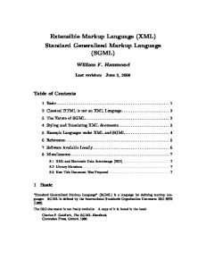
• id to assign a persistent globally unique URI • name to assign a human readable string 2.1.12 Link Group A LinkGroup is an unordered set of Link s. A LinkGroup may have the following relations: • existsDuring to one or more Lifetimes • hasLabelGroup to one LabelGroup • hasLink to one or more Link s or LinkGroups • isAlias to one or more LinkGroups • isSerialCompoundLink to Ordered List of LinkGroups A LinkGroup may have the following attributes: • id to assign a persistent globally unique URI • name to assign a human readable string 2.1.13 Bidirectional Port A BidirectionalPort is a group of two (unidirectional) Ports or PortGroups together forming a bidirectional representation of a physical or virtual port. See Figure 2 for an example of a BidirectionalPort and its associated Ports. A BidirectionalPort may have the following relations: • existsDuring to one or more Lifetimes • hasPort to exactly two Ports or two PortGroups A BidirectionalPort may have the following attributes: • encoding to assign a data encoding identifier • id to assign a persistent globally unique URI • name to assign a human readable string There is explicitly no direct relation between a BidirectionalPort and a BidirectionalLink, since NML is a unidirectional model.
15
GFD-R-P.206
May 2013
Bidirectional Port A
Bidirectional Link bi-A-B
hasPort
hasPort
hasLink Port A-out
isSource
Port A-in
isSink
Link A-B
hasLink
Link B-A
Figure 2: An abstract example of BidirectionalPort and BidirectionalLink 2.1.14 Bidirectional Link A BidirectionalLink is a group of two (unidirectional) Link s or LinkGroups together forming a bidirectional link. See Figure 2 for an example of a BidirectionalLink and its associated Link s. A BidirectionalLink may have the following relations: • existsDuring to one or more Lifetimes • hasLink to exactly two Link s or two LinkGroups A BidirectionalLink may have the following attributes: • encoding to assign a data encoding identifier • id to assign a persistent globally unique URI • name to assign a human readable string There is explicitly no direct relation between a BidirectionalPort and a BidirectionalLink, since NML is a unidirectional model. 2.1.15 Location A Location is a reference to a geographical location or area. A Location object can be related to other Network Objects to describe that these are located there. This can be relevant for network measurements, visualisations, et cetera. A Location may have the following attributes:
16
GFD-R-P.206
May 2013
• id to assign a persistent globally unique URI • name to assign a human readable string • long is the longitude in WGS84 coordinate system (in decimal degrees) [WGS84] • lat is the latitude in WGS84 coordinate system (in decimal degrees) • alt is the altitude in WGS84 coordinate system (in decimal meters) • unlocode is the UN/LOCODE location identifier [UNLOCODE] • address is a vCard ADR (address) property. The exact syntax of the address property is not specified, to allow other (e.g. XML or RDF) representations of the string-based format specified in [RFC 6350]. 2.1.16 Lifetime A Lifetime is an interval between which the object is said to be active. This can be used to track changes in a network, reflect dynamic operations, to help debug problems, et cetera. A Lifetime may have the following attributes: • start is the start time and date formatted as ISO 8601 calendar date, and should be a basic (compact) representation with UTC timezone (YYYYMMDD Thhmmss Z) [ISO 8601] • end is the end time and date formatted as ISO 8601 calendar date, and should be a basic (compact) representation with UTC timezone (YYYYMMDD Thhmmss Z) Objects with multiple lifetimes mean that the lifetime of the object is the union of all lifetimes (as opposed to a intersection). If a Network Object has no associated Lifetime objects, or the start or end attribute of a Lifetime object is missing, the default lifetime may be assumed to start on or before the time specified in the version attribute of the most specific Topology object that contains this Network Object. The end of that assumed lifetime is indefinite, until a Topology object with a higher version number is published. This new description can define a new Lifetime for the object, or the Topology. If the new description does not contain the Network Object, the end time is assumed to have passed. If a Network Object has no associated Lifetime objects, and the Topology object does not have a version attribute, than the lifetime of the Network Object is undefined.
17
GFD-R-P.206
May 2013
2.1.17 Label A Label is the technology-specific value that distinguishes a single data stream (a channel) embedded in a larger data stream. The Label can be a resource label (with one value). In a future extension it may be a pair of source and destination labels (with two values) [G.800]. Examples of resource labels are a VLAN number, wavelength, et cetera. A Label may have the following attributes: • labeltype to refer to a technology-specific labelset, e.g. a URI for VLANs • value is one specific value taken from the labelset, e.g. a VLAN number Technology extensions of NML may define additional attributes. Label type URIs should be specified in a Grid Forum Documents (GFD), which should also define possible values. This version of NML only deals with resource labels. The use of source and destination labels is a future extension [Dijkstra13]. 2.1.18 Label Group A LabelGroup is an unordered set of Label s. A LabelGroup may have the following attributes: • labeltype to refer to a technology-specific labelset • values is a set of specific values taken from the labelset Technology extensions of NML may define additional attributes. 2.1.19 Ordered List An Ordered List is an ordered list of Network Objects. These are used for the isSerialCompoundLink relation to an ordered list of Link s to describe a path through the network. The representation of an Ordered List depends on the syntax, and is defined in section 4.4. 2.1.20 List Item A ListItem is a syntactical construct which may be used by syntaxes to construct a Ordered List. The exact usage depends on the syntax.
18
GFD-R-P.206
May 2013
2.2 Relations Relations describe how different Network Objects relate to each other, typically to form a network topology description. The relations have been listed above, and are defined here (in alphabetical order). In principle a Relation can go from any object to any other object. The list below makes a distinction between allowed and defined relations. An allowed relation means it is valid NML. A defined relation means that it has a specific meaning, as described here. A relation which is not allowed must be rejected by a client, and the sender should be notified with an error. A relation which is allowed, but (yet) undefined should be ignored by a client (either silently, or with a warning to the sender). This distinction allows future extension of NML, while retaining limited backward compatibility. The existsDuring, hasLabel, hasLabelGroup, hasLink, hasNode, hasPort, hasService, hasTopology, locatedAt, providesLink, and providesPort are defined as implicit relations. All other relations are explicit. The distinction between implicit and explicit relations may be used by a syntax to allow a more compact network description. 2.2.1 canProvidePort canProvidePort is used to relate an AdaptationService or DeadaptationService to one or more Ports or PortGroups to define that these can be created by that AdaptationService or DeadaptationService. Allowed relations are: • Service canProvidePort § Port * * • Service canProvidePort § PortGroup * * Defined relations are: • AdaptationService canProvidePort § Port * * • AdaptationService canProvidePort § PortGroup * * • DeadaptationService canProvidePort § Port * * • DeadaptationService canProvidePort § PortGroup * *
19
GFD-R-P.206
May 2013
2.2.2 existsDuring existsDuring relates one Network Object object to zero or more LifeTime objects. This defines the existence of the object at a certain time. existsDuring § LifeTime 1 * Objects with multiple lifetimes mean that the lifetime of the object is the union of all lifetimes (as opposed to a intersection). Network Object
If a Network Object has no associated Lifetime objects, or the start or end attribute of a Lifetime object is missing, the default lifetime may be assumed to start on or before the time specified in the version attribute of the most specific Topology object that contains this Network Object, and the end on or later than the version attribute of the next published Topology object. If a Network Object has no associated Lifetime objects, and the Topology object does not have a version attribute, then the lifetime of the Network Object is undefined. 2.2.3 hasInboundPort hasInboundPort defines the relation between a Node, a SwitchingService or a Topology and their respective Ports or PortGroups Allowed relations are: • Network Object • Network Object
hasInboundPort § *
* hasInboundPort §
*
*
Port PortGroup
Defined relations are: • Node hasInboundPort § Port * * • Node hasInboundPort § PortGroup * * • SwitchingService hasInboundPort § Port * * • SwitchingService hasInboundPort § PortGroup * * • Topology hasInboundPort § Port * * • Topology hasInboundPort § PortGroup * *
20
GFD-R-P.206
May 2013
This defines that the related Network Object has an inbound Port or PortGroup object. The direction of the Port object is relative to the Network Object the Port is attached to, so in this case the traffic flows towards that Network Object (similarly for the PortGroup). This Port would then be related to a Link object using the isSink relation (or a PortGroup and LinkGroup respectively). A Network Object with a hasInboundPort relation pointing to a PortGroup has the same meaning as defining a hasInboundPort relation pointing to every Port in that PortGroup (as defined by a hasPort relation between the PortGroup and Port). 2.2.4 hasLabel hasLabel assigns one Label to a Port or Link Allowed relations are: • Port hasLabel § Label 1 * • Link hasLabel § Label 1 * The Label assigned to a Port or Link is the technology label that identifies the traffic through this Port or Link (including in Link s provided by a SwitchingMatrix ). A Label is used to distinguish a Port in a PortGroup, or distinguish a Link in a LinkGroup. The meaning of hasLabel is only defined for a cardinality of 0 or 1. 2.2.5 hasLabelGroup hasLabelGroup assigns one LabelGroup to a PortGroup or LinkGroup Allowed relations are: • PortGroup hasLabelGroup § LabelGroup 1 * • LinkGroup hasLabelGroup § LabelGroup 1 * The LabelGroup assigned to this PortGroup or LinkGroup defines the Label s associated with the Ports member of that group. There must be a one-to-one correspondence between the LabelGroup and the PortGroup. The meaning of hasLabelGroup is only defined for a cardinality of 0 or 1.
21
GFD-R-P.206
May 2013
2.2.6 hasLink hasLink is used for: • BidirectionalLink to relate exactly two Link s or two LinkGroups • LinkGroup to one or more Link s or LinkGroups to define membership of that group Allowed relations are: • Group hasLink § Link * * • Group hasLink § LinkGroup * * Defined relations are: • LinkGroup hasLink § Link * * • LinkGroup hasLink § LinkGroup * * • BidirectionalLink hasLink § Link * 2 • BidirectionalLink hasLink § LinkGroup * 2 The hasLink relationships for a BidirectionalLink point to the two unidirectional Link s that together form a bidirectional connection between its respective associated Nodes. The hasLink relationships for a LinkGroup define the membership of the Link s in that LinkGroup. 2.2.7 hasNode hasNode relates a Topology to a Node, meaning that a Node is part of a Topology Allowed relations are: • Network Object
hasNode § *
*
Node
Defined relations are: • Topology hasNode § Node * * 2.2.8 hasOutboundPort hasOutboundPort relates either a Node, SwitchingService or a Topology to one or more Ports or PortGroups. 22
GFD-R-P.206
May 2013
Allowed relations are: • Network Object • Network Object
hasOutboundPort § *
* hasOutboundPort §
*
*
Port PortGroup
Defined relations are: • Node hasOutboundPort § Port * * • Node hasOutboundPort § PortGroup * * • SwitchingService hasOutboundPort § Port * * • SwitchingService hasOutboundPort § PortGroup * * • Topology hasOutboundPort § Port * * • Topology hasOutboundPort § PortGroup * * This defines that the related Network Object has an outbound Port or PortGroup object. The direction of the Port object is relative to the Network Object the Port is attached to, so in this case the traffic flows away from that Network Object (similarly for the PortGroup). This Port would then be related to a Link object using the isSource relation (or az PortGroup and LinkGroup respectively). A Network Object with a hasOutboundPort relation pointing to a PortGroup has the same meaning as defining a hasOutboundPort relation pointing to every Port in that PortGroup (as defined by a hasPort relation between the PortGroup and Port). 2.2.9 hasPort hasPort is used for: • BidirectionalPort to relate exactly two Ports or two PortGroups • PortGroup to one or more Ports or PortGroups Allowed relations are: • Group hasPort § Port * * • Group hasPort § PortGroup * * Defined relations are: 23
GFD-R-P.206 • PortGroup • PortGroup
May 2013 hasPort § *
*
Port
hasPort §
PortGroup * • BidirectionalPort hasPort § Port * 2 • BidirectionalPort hasPort § PortGroup * 2 The hasPort relationships for a BidirectionalPort point to the two unidirectional Ports that together form a bidirectional port for the associated Node. These Ports would have a hasInboundPort and hasOutboundPort relation with that Node. *
The hasPort relationships for a PortGroup define the membership of the Ports in that PortGroup. 2.2.10 hasService hasService relates a Network Object to a Service. This schema only defines the meaning of: • Port to AdaptationService, relating one server-layer Port to an adaptation function. • Port to DeadaptationService, relating one server-layer Port to a deadaptation function. • Node or Topology to SwitchingService, describing a switching ability of that Node or Topology. Allowed relations are: • Network Object
hasService § *
*
Service
Defined relations are: • Port hasService § AdaptationService 1 * • Port hasService § DeadaptationService 1 * • Node hasService § SwitchingService * * • Topology hasService § SwitchingService * * A Port object can have a hasService relation to a Service, however the SwitchingService defines a more specific relation hasInboundPort / hasOutboundPort relation to a Port object. The latter relation is preferred over the hasService relation of the Port to the SwitchingService.
24
GFD-R-P.206
May 2013
2.2.11 hasTopology hasTopology defines a relation between one Topology to one or more Topologys for aggregation purposes. Allowed relations are: • Network Object
hasTopology § *
*
Topology
Defined relations are: • Topology hasTopology § Topology * * 2.2.12 implementedBy implementedBy relates a Node to one or more Nodes to describe virtualization or partitioning of a Node. The relation may be recursive, thus a virtual Node may be further partitioned. Allowed relations are: • Network Object
implementedBy § *
*
Network Object
Defined relations are: • Node implementedBy § Node * * 2.2.13 isAlias isAlias is a relation from a Network Object to a Network Object to describe that one can be used as the alias of another. Allowed relations are: isAlias § Network Object * * The relation is only defined if the type of both objects is the same (e.g. a Node can be related to another Node, but if it is related to a Topology using the isAlias relation, that relation is undefined.) • Network Object
2.2.14 isSerialCompoundLink isSerialCompoundLink is used to define that a Link or LinkGroup represents an Ordered List of Link s or LinkGroups. This must include cross-connects. The following relation is allowed and defined:
25
GFD-R-P.206
May 2013
1. Link 2. Link • Link isSerialCompoundLink § ... 1 * n. Link The following relation is allowed, but undefined: 1. LinkGroup • LinkGroup
isSerialCompoundLink § *
2. LinkGroup ... * n. LinkGroup
2.2.15 isSink isSink relates a Port to one Link to define the outgoing traffic port, and similarly for PortGroup and LinkGroup. Allowed relations are: • Network Object • Network Object
isSink § *
* isSink §
*
*
Link LinkGroup
Defined relations are: • Port isSink § Link * * • PortGroup isSink § LinkGroup * * isSink between a PortGroups and a LinkGroup is defined only if the PortGroup and LinkGroup in question have the exact same LabelGroup. 2.2.16 isSource isSource relates a Port to one Link to define its incoming traffic port, and similarly for PortGroup and LinkGroup. Allowed relations are: • Network Object • Network Object
isSource § *
* isSource §
*
*
Link LinkGroup
Defined relations are: 26
GFD-R-P.206 • Port
May 2013 isSource §
Link * • PortGroup isSource § LinkGroup * * isSource between a PortGroups and a LinkGroup is defined only if the PortGroup and LinkGroup in question have the exact same LabelGroup. *
2.2.17 item A item relation is a syntactical construct which may be used by syntaxes to construct a Ordered List. The exact usage depends on the syntax. 2.2.18 locatedAt locatedAt relates a Network Object to one Location to describe that a Network Object is located at that Location. • Network Object locatedAt § Location * * 2.2.19 next next relation is a syntactical construct which may be used by syntaxes to construct a Ordered List. The exact usage depends on the syntax. 2.2.20 providesLink providesLink is used to relate a SwitchingService to one or more Link s or LinkGroups to define that these have been created by that SwitchingService. Allowed relations are: • Service providesLink § Link * * • Service providesLink § LinkGroup * * Defined relations are: • SwitchingService providesLink § Link 1 * • SwitchingService providesLink § LinkGroup 1 *
27
GFD-R-P.206
May 2013
2.2.21 providesPort providesPort is used to relate an AdaptationService or DeadaptationService to one or more Ports or PortGroups to define that these have been created by that AdaptationService or DeadaptationService. Allowed relations are: • Service providesPort § Port * * • Service providesPort § PortGroup * * Defined relations are: • AdaptationService providesPort § Port 1 * • AdaptationService providesPort § PortGroup 1 * • DeadaptationService providesPort § Port 1 * • DeadaptationService providesPort § PortGroup 1 *
2.3 Attributes Attributes are properties of an object. The following attributes have been defined in section 2.1.
28
GFD-R-P.206 Attribute adaptationFunction address alt encoding
end id labeltype lat long name start unlocode value values version
May 2013 Class (section) AdaptationService (2.1.7), DeadaptationService (2.1.8) Location (2.1.15) Location (2.1.15) Port (2.1.3), Link (2.1.4), PortGroup (2.1.11), LinkGroup (2.1.12), BidirectionalPort (2.1.14), BidirectionalLink (2.1.14),SwitchingService (2.1.6) LifeTime (2.1.16) NetworkObject (2.1.1), Location (2.1.15) Label (2.1.17), LabelGroup (2.1.18) Location (2.1.15) Location (2.1.15) NetworkObject, Location (2.1.15) LifeTime (2.1.16) Location (2.1.15) Label (2.1.17) LabelGroup (2.1.18) NetworkObject (2.1.1)
2.4 Parameters Parameters are properties of an object. Parameters, like attributes, are properties of objects, but may (subtly) change the logic of the object. The following parameters have been defined in section 2.1. Parameter labelSwapping noReturnTraffic
Class (section) SwitchingService (2.1.6) Link (2.1.4)
29
GFD-R-P.206
May 2013
3 Identifiers 3.1 Schema Identifier The namespace for the schema defined in document is http://schemas.ogf.org/nml/2013/ 05/base\#. All classes, relations, parameters and attributes defined in this document reside in this namespace. For example, the Link class is identified by http://schemas.ogf.org/nml/2013/05/base#Link
3.2 Instance Identifiers Section 2.1.1 requires that instances of Network Objects should have an id attribute, which must be a unique URI. Implementations that receive a network topology description must be prepared to accept any valid URI as an identifier. Implementations that publish a network topology description instance identifiers may adhere to the syntax of Global Network Identifiers as defined in [GFD.202], which ensures global uniqueness and easy recognition as Network Object instances. Two different Network Objects instances must have two different identifiers. Once an identifier is assigned to a resource, it must not be re-assigned to another resource. A URI may be interpreted as an International Resource Identifier (IRI) for display purposes, but URIs from external source domains must not be IRI-normalised before transmitting to others. 3.2.1 Lexical Equivalence Two identifier are lexical equivalent if they are binary equivalent after case folding2 [Unicode]. Other interpretation (such as percent-decoding or Punycode decoding [RFC 3492]) must not take place. For the purpose of equivalence comparison, any possible fragment part or query part of the URI is considered part of the URI. For example the following identifiers are equivalent: 2
Case folding is primarily used for caseless comparison of text. Case mapping is used for display purposes.
30
GFD-R-P.206
May 2013
1 - urn:ogf:network:example.net:2013:local_string_1234 2 - URN:OGF:network:EXAMPLE.NET:2013:Local_String_1234 While the following identifiers are not equivalent (in this case, the percentage encoding even makes URI #3 an invalid Global Network Identifier.): 1 - urn:ogf:network:example.net:2013:local_string_1234 3 - urn:ogf:network:example.net:2013:local%5Fstring%5F1234 3.2.2 Further Restrictions An assigning organisation must not assign Network Object Identifier longer than 255 characters in length. Parsers must be prepared to accept identifiers of up to 255 characters in length. A Parser should verify if an identifier adheres to the general URI syntax rules, as specified in RFC 3986 [RFC 3986]. Parsers should reject identifiers which do not adhere to the specified rules. A parser encountering an invalid identifier should reply with an error code that includes the malformed identifier, but may accept the rest of the message, after purging all references to the Network Object with the malformed identifier. 3.2.3 Interpreting Identifiers A Network Object identifier must be treated as a opaque string, only used to uniquely identify a Network Object. The local-part of a Global Network Identifier may have certain meaning to it’s assigning organisation, but must not be interpreted by any other organisation. 3.2.4 Network Object Attribute Change A Network Object may change during its lifetime. If these changes are so drastic that the assigning organisation considers it a completely new Network Object, the assigning organisation should be assigned a new identifier. In this case, other organisations MUST treat this object as completely new Network Resource. If the assigning organisation considers the changes are small, it must retain the same identifier for the Network Object, and use some mechanism to signal it’s peers of the changes in the attributes of the Network Object. An appropriate mechanism is to send a new description of the Topology or the Network Object with an updated version attribute.
31
GFD-R-P.206
May 2013
3.3 Unnamed Objects Network Objects that do not have a regular URI as id attribute, may have either: • Have no id attribute. These are so-called unnamed network objects. • Have an id attribute which is a fragment identifier only, thus an URI starting with a crosshatch (#) character. These are so-called ad-hoc named network objects. A unnamed network object can not be referenced. A network objects generally should not be unnamed, since there is no possibility for an external party to refer to the object. A ad-hoc named network object can only be referenced from within the same topology description. ad-hoc id s must be considered a syntactical construct, not as a persistent identifier. The must not be referred to from another scope or another topology description. ad-hoc id s should not be stored. If a two peers exchange topology messages, it is perfectly valid to change the ad-hoc id in each message (since they are only valid within scope of that message anyway). A possible reason to use unnamed or ad-hoc named network objects it to make a statement such as “Port A and Port B are grouped in a BidirectionalPort” without actually assigning an identifier to this BidirectionalPort.
32
GFD-R-P.206
May 2013
4 Syntax The Network Markup Language has two different normative syntaxes. The syntaxes are in regular XML defined using an XML Schema (XSD), and another in OWL RDF/XML syntax, defined in an OWL schema. The OWL syntax is aimed at Semantic Web-oriented applications, the XML syntax is suitable for any application. These syntaxes are defined in Appendices A and B respectively. These syntaxes follow the model as defined in section 2, should there be any inconsistencies between the syntaxes or the syntaxes and the model, the definitions in section 2 take precedence.
4.1 XML Syntax An NML object is represented as an XML element. For example: 1
An NML attribute or parameter is represented as either an XML attribute, XML child element or text value of the XML element. The table list the mapping for the attributes and parameters defined in this document: XML representation NML attribute or parameter
Attribute Child element Text of element id name value adaptationFunction address values encoding lat labeltype long version alt noReturnTraffic unlocode labelSwapping start end
For example: 1 2 3 4
VLAN 1501 at Port X (in) 1501
Explicit relation are represented as a XML element, with the domain as the parent element, and the range as the child element. Implicit relations are not given: the range object is represented as an XML child element of the domain. Below is an example of an explicit relation: 33
GFD-R-P.206
1 2 3 4 5
May 2013
And this is an example of an implicit relation: 1 2 3
4.2 OWL RDF/XML Syntax An NML object is represented as an RDF subject. Exceptions are Label and LabelGroup. An NML attribute or parameter is represented as a predicate. For example: 1 2 3 4 5
Red City 30.600 12.640
Relations are represented as an RDF triplet, with the full URI of the attribute or parameter. For example: 1 2 3
A Label is represented as a two triplets: one triplet defining a labeltype as a subproperty of the abstract Label resource, and one relating a Port or Link to a value using this labeltype. For example: 1 2 3 4 5 6
1501
34
GFD-R-P.206
May 2013
A LabelGroup is represented as three triplets. The URI of the labeltype is not the URI of the predicate, to avoid naming clashes with the definition of the Label. Instead, the predicate of the LabelGroup is related to the predicate of the Label using the nml:labeltype property: 1 2 3 4 5 6 7
1480´1530
4.3 Combining Object Descriptions A given object may have multiple attributes and relations. These attributes and relations may be described in different places in a syntax. It is up to the parser to combine all attributes and relations. NML currently does not have a mechanism to check if a given description of an object is complete. Thus, it does not distinguish between a full description of an object or merely a pointer to an object. Parsers should be aware that the NML descriptions do not provide any guarantee regarding the integrity nor the authenticity of the description. Parsers are advised to use external mechanism to avoid that an erroneous description of an object in one (possibly malicious) topology description pollutes a correct description of the same object in another topology description.
4.4 Ordered Lists The range of an isSerialCompoundLink relation is an Ordered List. Neither XML nor OWL uses the Ordered List directly in the syntax, and have a different way of constructing ordered lists. XML lists values with additional next relations, while OWL uses a ListItem class, and the item and next relations. A ListItem behaves as a class, while item and next behave like relations, with the exception that these classes and relations are local in scope. This means that these relations are only valid within the scope of a given Ordered List, but may not be valid in scope of a different Ordered List. It also means that any identifier given to these classes may change when the objects are codified in a syntax.
35
GFD-R-P.206
May 2013
For example, consider the following two decompositions of Link Link_1_2_3 into shorter Links: Link_1 • Link_1_2_3
isSerialCompoundLink §
Link_2 Link_3
• Link_1_2_3
isSerialCompoundLink §
Link_1 Link_2_3
In the first Ordered List, there is a next relation from Link_1 to Link_2, while in the second Ordered List, the next relation is from Link_1 to Link_2_3. In XML an Ordered List can be constructed by using all objects in the list as child elements, and using a next relation between consecutive objects in the list to denote ordering. In OWL an Ordered List can be constructed by creating as many ListItem objects as there are items in the list. Each ListItem object is correlated with the actual list item using the item relation, while using a next relation to point to the following ListItem. A predicate points to the first ListItem in the Ordered List to point to the whole list, which is chained using the next relation. See also the isSerialCompoundLink examples in the example section.
36
hasPort
Port port_X:in
Port port_X:out
hasLabelGroup
hasService
hasService
PortGroup portgroup_X:out
DeadaptationService port_X:in: deadaptationService
AdaptationService port_X:out: adaptationService
hasOutboundPort
labeltype
values
labeltype
value
1501
ethernet#vlan
1480-1530
ethernet#vlan
1501
Link LinkA:XY
isSink
Port port_Y:in
Link link_WX
Link link_XW
isSerialCompoundLink
Link LinkB:YZ
isSource
Port port_Y:out
name long
BidirectionalLink link_XWX
hasLink
hasLink
Group
Port port_Z:in
12.640
Link LinkC:ZW
isSink
30.600
lat
Location redcity
Red City
hasInboundPort
hasInboundPort
locatedAt
hasOutboundPort
providesLink isSource
hasLabel
Group
Labelgroup
Label
providesPort
providesPort
Node nodeA
SwitchingService nodeA:switching Service hasInboundPort
Port port_X.1501:in
hasOutboundPort
hasInboundPort
Port port_X.1501:out
hasPort hasPort
BidirectionalPort port_X.1501
hasNode
hasOutboundPort
20130521
version
Topology org
GFD-R-P.206 May 2013
5 Examples
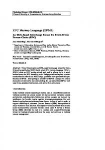
A graphical overview showing the combination of all the examples is shown in figure 3.
Figure 3: A graphical overview showing the combination of all examples
37
GFD-R-P.206
May 2013
5.1 Examples in XML The following snippets represent NML structures in the XML format. • Topology (section 2.1.10) 1 2 3 4
5 6
7 8
9 10
• Node (section 2.1.2) 1 2 3 4 5 6 7 8 9 10 11 12
Node_A
• Ports – (Unidirectional) Port (section 2.1.3) 1 2 3
1501
– BidirectionalPort (section 2.1.13) 1 2 3 4 5
X.1501
38
GFD-R-P.206
May 2013
– PortGroup (section 2.1.11) 1 2 3 4 5 6
1480´1530
• Links – UnidirectionalLink (external) (section 2.1.4) 1
2 3 4 5 6
7 8 9 10 11 12
13 14
– UnidirectionalLink (internal) (section 2.1.4) 1
2 3 4 5 6 7
8 9 10 11 12 13
– UnidirectionalLink that is composed of more than one sub-link 1 2 3 4 5
39
GFD-R-P.206 6 7 8 9 10 11 12 13 14 15
May 2013
– BidirectionalLink (section 2.1.14) 1 2 3 4 5
Link between ports X and W
– LinkGroup (section 2.1.12) 1 2 3 4 5
1480´1530
• Labels – Label (section 2.1.17) 1
1501
– LabelGroup (section 2.1.18) 1 2 3
1480´1530
• Location (section 2.1.15) 1 2 3 4 5
Red City 30.600 12.640
40
GFD-R-P.206
May 2013
• Services – SwitchingService (section 2.1.6) 1 2 3 4 5 6 7 8 9 10 11 12 13 14
Node_A
15 16 17 18 19 20 21 22 23 24 25 26 27 28
– AdaptationService (section 2.1.7) 1 2 3 4 5
6 7 8 9 10 11 12 13
14 15 16 17
1501
– DeadaptationService (section 2.1.8) 41
GFD-R-P.206
1 2 3 4 5
May 2013
6 7 8 9 10 11 12 13
14 15 16 17
1501
42
GFD-R-P.206
May 2013
5.2 Examples in OWL The following snippets represent NML structures in the OWL format. The namespaces used in all the examples follow the definitions of the Topology example. • Topology (section 2.1.10) 1 2 3 4 5 6 7 8 9 10 11
20130529T121112Z
12 13
• Node (section 2.1.2) 1 2 3 4 5 6 7 8
Node_A
• Ports – (Unidirectional) Port (section 2.1.3) 1 2 3
1501
– BidirectionalPort (section 2.1.13) 1 2 3 4 5
X.1501
43
GFD-R-P.206
May 2013
– PortGroup (section 2.1.11) 1 2 3 4 5 6
1480´1530
• Links – UnidirectionalLink (external) (section 2.1.4) 1
2 3 4 5
6 7 8 9
– UnidirectionalLink (internal) (section 2.1.4) 1
2 3 4 5
6 7 8 9
– UnidirectionalLink that is composed of more than one sub-link 1 2 3 4 5 6 7 8
9 10 11 12 13
14
44
GFD-R-P.206 15 16 17
May 2013
– BidirectionalLink (section 2.1.14) 1 2 3 4 5
Link between ports X and W
– LinkGroup (section 2.1.12) 1 2 3
1480´1530
• Labels – Label (section 2.1.17) 1 2 3 4 5 6
1501
– LabelGroup (section 2.1.18) 1 2 3 4 5 6 7
1480´1530
• Location (section 2.1.15) 1 2 3 4 5
Red City 30.600 12.640
45
GFD-R-P.206
May 2013
• Services – SwitchingService (section 2.1.6) 1 2 3 4 5 6 7 8
Node_A
9 10 11 12 13 14 15
– AdaptationService (section 2.1.7) 1 2 3 4 5 6 7 8 9
10 11 12 13
1501
– DeadaptationService (section 2.1.8) 1 2 3 4 5 6 7 8 9
10 11 12 13
1501
46
GFD-R-P.206
May 2013
5.3 Conceptual Examples This section shows a few examples how NML was designed to be used. Like the other examples, this section is informative. It may be possible that there are other ways to use the NML objects and attributes. 5.3.1 Topology and Node A Topology and Node behave similar: they both contain inbound ports and outbound ports, and can contain a SwitchingService to allow creation of internal links (cross connects) from inbound ports to outbound ports. Especially with the ability to create logical, sliced or virtual devices, the distinction is getting blurred. The distinction is that a Node is located at a single geographic location, while a Topology is a set of geographically disperse Network Objects. 5.3.2 Hierarchical Topology Large networks may want to publish both details of their network topology as a whole, as well as details about regional segments, without publishing details of the actual devices. NML allows the publication of a hierarchical Topology tree, where the top-level Topology has a hasTopology relation with smaller Topologies. These smaller Topologies must be fully enclosed – the hasTopology relation can not be used to relate partial overlapping Topologies. For example, a Topology A may want to publish about two parts of its Topology, A_West, and A_East. This allows it to publish difference in connectivity and costs between the two parts. It can do so with the following relations: Topology A
hasTopology §
Topology A_West
Topology A
hasTopology §
Topology A_East
5.3.3 Links, Segments and Paths A Link object can refer to any link connection. A link segment and an end-to-end path are both described by a Link object. This is by design, since it is easy to extend a Link, or to describe a partition of a Link. Figure 4 gives an example of three different partitionings of a link between port_X:in and port_W:out. Note that in this example Port port_Y:out is the source of both linkB:YZ and of linkBC:YW. If a single topology description would contain the full link and the partitioning, a path finding 47
GFD-R-P.206
May 2013 LinkA:XY
X:in
LinkB:YZ
Y:out LinkAB:XZ
X:in LinkA:XY
X:in
Z:in
Z:in
LinkC:ZW
LinkC:ZW
LinkBC:YW
Y:out
W:out
W:out
W:out
Figure 4: Different partitionings of the same link. algoritm must be aware that the fact that if a Port is the source of two NML Links, this does not mean it multicast to different network links. For this reason, it is recommended that applications either add metadata about the type of link, or specify that in certain messages, only one particular type of Link must be used. 5.3.4 Patch Panel and Media Convertor A port on a patch panel or optical distribution frame can simply be described as a NML Port (thus without an associated Node): Port odf_X
isSink §
Port odf_X
isSource §
Link A Link B
A mediaconvertor, e.g. from Ethernet over UTP to Ethernet over fiber, can be described in the same way, provided that the connected Links described the Ethernet connections. If the connected Links describe the underlying UTP and fiber connections, it is necessary to describe the conversion between them: Port Port_X_UTP isSink § Link UTP_A Port Port_X_fiber Port Port_X_UTP Port Port_X_fiber
isSource § hasService §
Link fiber_B DeAdaptataionService X_deadaptation
hasService §
AdaptationService X_adaptation DeAdaptataionService X_deadaptation providesPort § Port Port_X_eth AdaptationService X_adaptation providesPort § Port Port_X_eth 5.3.5 VLAN and Broadcast Medium A VLAN is much like a broadcast medium, which can be described as a multipoint-tomultipoint Link:
48
GFD-R-P.206 Port Port_X:in Port Port_X:out Port Port_Y:in Port Port_Y:out Port Port_Z:in Port Port_Z:out
May 2013 isSink §
Link VLAN_42
isSink § isSink §
Link VLAN_42 Link VLAN_42
isSink § isSink §
Link VLAN_42 Link VLAN_42
isSink §
Link VLAN_42
Where X, Y and Z are in fact bidirectional ports: BidirectionalPort Port_X
hasPort §
Port Port_X:in
BidirectionalPort Port_X
hasPort §
Port Port_X:out
BidirectionalPort Port_Y
hasPort §
Port Port_Y:in
BidirectionalPort Port_Y
hasPort §
Port Port_Y:out
BidirectionalPort Port_Z
hasPort §
Port Port_Z:in
BidirectionalPort Port_Z
hasPort §
Port Port_Z:out
However, this is not entirely correct: in the above description data coming from Port_X:in would also be forwarded to Port_X:out. However, the Ethernet technology prevents data returning on the same interface. NML introduced the noReturnTraffic parameter to describe this technological restriction: if the noReturnTraffic parameter of a Link is true, there is no data transport from a source to a sink if the source and sink are grouped together in a BidirectionalPort group. Link VLAN_42
noReturnTraffic §
"true"
5.3.6 Configuration and Potential Capability NML is able to both describe the network services (potential capability) as well as the network configuration. A switching service can be described by a SwitchingService object along with associated inbound ports and outbound ports: SwitchingService switchmatrix_A
hasInboundPort §
SwitchingService switchmatrix_A
hasOutboundPort §
PortGroup Port_X:in PortGroup Port_X:out 49
GFD-R-P.206
May 2013
SwitchingService switchmatrix_A
hasInboundPort §
SwitchingService switchmatrix_A
hasOutboundPort §
SwitchingService switchmatrix_A
labelSwapping §
PortGroup Port_Y:in PortGroup Port_Y:out
true
A cross connect created by this switching service can be specified by a Link object: SwitchingService switchmatrix_A providesLink § Link crossconnect_A.1501 PortGroup Port_X:in hasPort § Port Port_X.1501:in PortGroup Port_Y:out hasPort § Port Port_Y.1501:out Port Port_X.1501:in
isSource §
Port Port_Y.1501:out
isSink §
Link crossconnect_A.1501 Link crossconnect_A.1501
An encoding and decoding service can be described by a AdapdationService and DeAdaptationService: Port Port_X_fiber:in hasService § DeAdaptationService port_X:in:deadaptation DeAdaptationService port_X:in:deadaptation
canProvidePort §
PortGroup Port_X:in
A channel created by this encoding service can be specified by a providesPort relation: DeAdaptationService port_X:in:deadaptation PortGroup Port_X:in
hasPort §
providesPort §
Port Port_X.1501:in
Port Port_X.1501:in
5.3.7 Versioning and Lifetime The version of a Topology indicated the serial number. If there are two Topology descriptions for the same network, the one with the highest version number is the most recent version. The LifeTime object is used to indicate when a certain resource is available. Imagine that a link will have a scheduled downtime due to maintenance next week between 2 AM and 4 AM. This can be specified with these relations: Topology org version § 20130521T000000Z Link A
existsDuring §
Link A
existsDuring §
LifeTime A_lifetime1
LifeTime A_lifetime1
LifeTime A_lifetime2 end § 20130611T020000Z
LifeTime A_lifetime2
start §
20130611T040000Z 50
GFD-R-P.206
May 2013
Imagine that this planned maintainance is rescheduled. That can be specified by creating a new Topology with a new version number, and updated data: Topology org version § 20130604T000000Z Link A
existsDuring §
Link A
existsDuring §
LifeTime A_lifetime1
LifeTime A_lifetime1
LifeTime A_lifetime2 end § 20130618T020000Z
LifeTime A_lifetime2
start §
20130618T040000Z
51
GFD-R-P.206
May 2013
6 Security Considerations There are important security concerns associated with the generation and distribution of network topology information. For example, ISPs frequently consider network topologies to be confidential. We do not address these concerns in this document, but implementers are encouraged to consider the security implications of generating and distributing network topology information. Implementers should be aware that the NML descriptions do not provide any guarantee regarding their integrity nor their authenticity. The NML documents also can not provide this for the identifiers contained in the documents. Implementers should use external means of verifying the authenticity of identifiers contained in the documents.
52
GFD-R-P.206
May 2013
7 Contributors Jeroen J. van der Ham (Editor) Faculty of Science, Informatics Institute, University of Amsterdam Science Park 904, 1098 XH Amsterdam The Netherlands Email:
[email protected] Freek Dijkstra SURFsara Science Park 140, 1098 XG Amsterdam The Netherlands Email:
[email protected] Roman Łapacz PSNC ul. Noskowskiego 12/14, 61-704 Poznań Poland Email:
[email protected] Jason Zurawski Internet2 1150 18th Street, NW Suite 900 Washington, DC 20036 USA Email:
[email protected]
8 Acknowledgments The authors would like to thank the NML working group members for their patience. The NML group has operated in the web of infrastructure groups and is grateful for all the input from the NM, NMC and NSI working-groups. Financial support has been provided by several projects and institutions: This work was partially supported by the European Commission, 7th Framework Programme for Research and Technological Development, Capacities, The GN3 project – Grant No. 238875, GEYSERS – Grant No. 248657 and NOVI – Grant No. 257867. This project was also made possible by the support of SURF, the collaborative organisation for higher 53
GFD-R-P.206
May 2013
education institutes and research institutes aimed at breakthrough innovations in ICT. More information on SURF is available on the website www.surf.nl. Furthermore, this work was supported by the Dutch national program COMMIT. Jason Zurawski would like to thank Internet2, along with the National Science Foundation (NSF) for support through grants: #0962704, #1019008, and #0721902. The authors are indebted to the many participants of working group sessions and on the mailing list, including the following contributors: Aaron Brown, Jeff W. Boote, Aurélien Cedeyn, Evangelos Chaniotakis, Chin Guok, Paola Grosso, Richard Hughes-Jones, Houssem Medhioub, Ralph Niederberger, Anand Patil, Victor Reijs, Guy Roberts, Jerry Sobieski, Martin Swany, Fausto Vetter, Pascale Vicat-Blanc, and John Vollbrecht.
54
GFD-R-P.206
May 2013
9 Intellectual Property Statement The OGF takes no position regarding the validity or scope of any intellectual property or other rights that might be claimed to pertain to the implementation or use of the technology described in this document or the extent to which any license under such rights might or might not be available; neither does it represent that it has made any effort to identify any such rights. Copies of claims of rights made available for publication and any assurances of licenses to be made available, or the result of an attempt made to obtain a general license or permission for the use of such proprietary rights by implementers or users of this specification can be obtained from the OGF Secretariat. The OGF invites any interested party to bring to its attention any copyrights, patents or patent applications, or other proprietary rights which may cover technology that may be required to practice this recommendation. Please address the information to the OGF Executive Director.
10 Disclaimer This document and the information contained herein is provided on an “As Is” basis and the OGF disclaims all warranties, express or implied, including but not limited to any warranty that the use of the information herein will not infringe any rights or any implied warranties of merchantability or fitness for a particular purpose.
11 Full Copyright Notice c Open Grid Forum (2008-2013). Some Rights Reserved. Copyright This document and translations of it may be copied and furnished to others, and derivative works that comment on or otherwise explain it or assist in its implementation may be prepared, copied, published and distributed, in whole or in part, without restriction of any kind, provided that the above copyright notice and this paragraph are included as references to the derived portions on all such copies and derivative works. The published OGF document from which such works are derived, however, may not be modified in any way, such as by removing the copyright notice or references to the OGF or other organizations, except as needed for the purpose of developing new or updated OGF documents in conformance with the procedures defined in the OGF Document Process, or as required to translate it into languages other than English. OGF, with the approval of its board, may remove this restriction for inclusion of OGF document content for the purpose of producing standards in cooperation with other international standards bodies.
55
GFD-R-P.206
May 2013
The limited permissions granted above are perpetual and will not be revoked by the OGF or its successors or assignees.
56
GFD-R-P.206
May 2013
Appendix A XML Schema This section describes the normative schema of XML documents using the XML Schema language. 1
2 3 4
5 6 7 8 9
File: nmlbase.xsd ´ Main XSD schema definition Version: $Id$ Purpose: This is the main XSD schema file, it defines the general topology elements of NML.
10 11
´´>
12 13 14 15 16
17 18 19 20 21 22 23 24 25 26 27
28 29 30 31 32 33 34 35 36 37 38 39 40 41 42 43 44 45 46 47
48 49 50 51 52
57
GFD-R-P.206 53 54 55
May 2013
56 57 58 59 60 61 62 63 64 65 66
67 68 69
70 71 72 73 74 75 76 77 78 79 80 81 82 83 84 85 86 87 88 89
90 91 92 93 94 95 96 97 98 99 100 101
102 103 104 105 106 107 108 109 110 111 112
58
GFD-R-P.206 113
May 2013
114 115 116
117 118 119
120 121 122 123 124 125 126 127 128 129 130 131 132 133 134 135
136 137 138 139 140 141 142 143
144 145 146 147 148 149 150 151 152 153 154 155 156 157
158 159 160
161 162 163
164 165 166 167 168 169 170 171 172
59
GFD-R-P.206 173 174 175 176 177 178 179 180 181 182
May 2013
183 184 185 186 187 188 189 190
191 192 193 194 195 196 197 198 199 200 201 202 203
204 205 206
207 208 209
210 211 212 213 214 215 216 217 218 219 220 221 222 223 224 225 226 227 228 229
230 231 232
60
GFD-R-P.206 233 234 235 236 237 238 239 240 241 242
May 2013
243 244 245
246 247 248
249 250 251 252 253 254 255 256 257
258 259 260
261 262 263 264 265 266 267 268 269 270 271 272 273 274 275 276 277 278 279 280 281
282 283 284 285 286 287 288 289 290 291
61
GFD-R-P.206 292 293 294
May 2013
295 296 297
298 299 300
301 302 303 304 305 306 307 308 309 310 311 312 313 314 315 316 317 318
319 320 321 322 323 324 325 326 327 328 329 330
331 332 333
334 335 336
337 338 339 340 341 342 343 344 345 346 347 348 349 350
62
GFD-R-P.206 351 352 353 354
May 2013
355 356 357 358 359 360 361 362 363 364 365 366
367 368 369
370 371 372
373 374 375 376 377 378 379 380 381
382 383 384
385 386 387
388 389 390 391 392 393 394 395 396 397 398 399 400 401 402
403 404 405 406 407 408 409
63
GFD-R-P.206 410 411
May 2013
412 413 414 415 416 417 418 419 420 421 422 423
424 425 426
427 428 429
430 431 432 433 434 435 436 437 438 439 440 441 442 443 444 445 446
447 448 449 450 451 452 453 454 455
456 457 458 459 460 461 462 463 464 465 466 467 468
469
64
GFD-R-P.206
May 2013
470 471
472 473 474 475
476 477 478 479 480 481 482 483 484 485 486 487 488 489
490 491 492 493 494 495 496 497 498
499 500 501
502 503 504
505 506 507 508 509 510 511 512 513 514 515 516 517 518
519 520 521 522 523 524 525 526 527
528 529
65
GFD-R-P.206 530
May 2013
531 532 533
534 535 536 537 538 539 540 541 542
543 544 545
546 547 548
66
GFD-R-P.206
May 2013
Appendix B OWL Schema This section describes the normative schema of the OWL syntax using the OWL ontology definition below. 1 2 3 4 5 6 7 8 9 10 11
NML Schema
12 13 14 15 16 17 18 19 20
21 22 23
24 25 26 27 28 29 30 31 32 33 34
35 36 37
38 39 40 41
42 43 44
45 46 47 48 49 50 51 52
67
GFD-R-P.206 53 54 55 56
May 2013
57 58 59
60 61 62 63 64 65 66 67 68 69 70 71 72 73
74 75 76
77 78 79 80 81
82 83 84
85 86 87 88 89 90 91 92 93 94 95 96
97 98 99
100 101 102 103 104 105 106 107 108 109 110 111
112
68
GFD-R-P.206
May 2013
113 114
115 116 117 118 119 120 121 122 123 124 125 126
127 128 129
130 131 132 133 134 135 136 137 138 139 140 141
142 143 144
145 146 147 148 149
150 151 152
153 154 155 156 157 158 159 160 161 162 163 164
165 166 167
168 169 170 171 172
69
GFD-R-P.206
May 2013
173 174 175
176 177 178 179 180
181 182 183
184 185 186 187 188
189 190 191
192 193 194 195 196
197 198 199
200 201 202 203 204
205 206 207
208 209 210 211 212 213 214 215 216 217 218 219
220 221 222
223 224 225 226 227 228 229 230 231 232
70
GFD-R-P.206 233 234
May 2013
235 236 237
238 239 240 241 242 243 244 245 246 247 248 249
250 251 252
253 254 255 256
257 258 259
260 261 262 263 264 265 266 267 268 269 270
271 272 273
274 275 276 277 278
279 280 281
282 283 284 285 286
287 288 289
290 291 292
71
GFD-R-P.206 293 294 295 296 297 298 299 300 301
May 2013
302 303 304
305 306 307 308 309 310 311 312 313 314 315 316
317 318 319 320 321 322 323 324 325
326 327 328
329 330 331 332 333
334 335 336
337 338 339 340 341
342 343 344
345 346 347 348 349
350 351 352
72
GFD-R-P.206
May 2013
353 354 355 356 357
358 359 360
361 362 363 364 365
366 367 368
369 370 371 372 373 374 375 376 377 378 379 380
381 382 383
384 385 386 387 388
389 390 391
392 393 394 395
396 397 398
399 400 401 402 403
404 405 406
407 408 409 410 411
412
73
GFD-R-P.206
May 2013
413 414
415 416 417 418 419
420 421 422
423 424 425 426 427
428 429 430
431 432 433 434 435
436 437 438 439 440 441 442 443 444
445 446 447 448
449 450 451 452
453 454 455
456 457 458 459
460 461 462
463 464 465 466
467 468 469
470 471 472
74
GFD-R-P.206 473
May 2013
474 475 476
477 478 479 480
481 482 483
484 485
486 487 488
489 490 491 492
493 494 495
496 497
498 499 500
501 502 503 504
505 506 507
508 509 510 511
512 513 514
515 516 517 518
519 520 521
522 523 524 525
526 527 528
529 530
531 532
75
GFD-R-P.206 533
May 2013
534 535 536 537
538 539 540
541 542 543 544
545 546 547
548 549 550 551
552 553 554
555 556 557 558
559 560 561
562 563 564 565
566 567 568
569 570 571 572 573
76
GFD-R-P.206
May 2013
Appendix C Relation to G.800 This section describes the relation between terms defined in this recommendation and those defined in the ITU-T G.800 recommendation [G.800]. NML Term Port Link SwitchingService AdaptationService BidirectionalPort Label
G.800 Term Unidirectional Port Either Link Connection or Network Connection Subnetwork Combined Adaptation Function and Termination Function Port Resource label
77
GFD-R-P.206
May 2013
References Normative References [GFD.202] Freek Dijkstra, and Jeroen van der Ham. A URN Namespace for Network Resources. GFD 202 (Community Practise), June 2013. URL http://www.ogf.org/ documents/GFD.202.pdf. [ISO 8601] Data elements and interchange formats – Information interchange – Representation of dates and times. ISO 8601:2004 (Third edition), December 2004. Section 4.3.2 (a), Complete representations of a date and time. Calendar date in basic format. URL http://www.iso.org/iso/home/store/catalogue_ics/catalogue_ detail_ics.htm?csnumber=40874. [G.800] Unified functional architecture of transport networks. ITU-T Recommendation G.800, February 2012. URL http://www.itu.int/rec/T-REC-G.800/. [RDF-XML] Dave Beckett (editor) RDF/XML Syntax Specification (Revised) W3C Recommendation 10 February 2004. URL http://www.w3.org/TR/rdf-syntax-grammar/. [RFC 2119] Scott Bradner. Key words for use in RFCs to Indicate Requirement Levels. RFC 2119 (Best Current Practice), March 1997. URL http://tools.ietf.org/html/ rfc2119. [RFC 3492] A. Costello Punycode: A Bootstring encoding of Unicode for Internationalized Domain Names in Applications (IDNA) RFC 3492 (Standards Track), March 2003 URL http://tools.ietf.org/html/rfc3492. [RFC 3986] Tim Berners-Lee, Roy T. Fielding, and Larry Masinter. Uniform Resource Identifier (URI): Generic Syntax RFC 3986 (Standards Track), January 2005. URL http://tools.ietf.org/html/rfc3986. [Unicode] The Unicode Consortium. The Unicode Standard, Version 6.2.0. Mountain View, CA, USA. November 2012. ISBN 978-1-936213-07-8 Section 5.18, Case Mappings. Paragraph about Caseless Matching. Normative URL http://www.unicode. org/versions/Unicode6.2.0/ Informative URL ftp://ftp.unicode.org/Public/ UNIDATA/CaseFolding.txt [UNLOCODE] United Nations Code for Trade and Transport Locations UN/LOCODE, revision 2012-01, September 2012. URL http://www.unece.org/cefact/locode/ welcome.html. 78
GFD-R-P.206
May 2013
[WGS84] Department of Defense World Geodetic System 1984, Its Definition and Relationships With Local Geodetic Systems NIMA Technical Report TR8350.2, Third Edition, June 2004 URL http://earth-info.nga.mil/GandG/publications/tr8350.2/ tr8350_2.html. [XML] Henry S. Thompson, David Beech, Murray Maloney and Noah Mendelsohn XML Schema Part 1: Structures Second Edition W3C Recommendation 28 October 2004. URL http://www.w3.org/TR/xmlschema-1/.
Informative References [Dijkstra13] Freek Dijkstra, et al. Experimental Features for NML 1. Work in Progress. [GFD.165] Paola Grosso, Aaron Brown, Aurélien Cedeyn, Freek Dijkstra, Jeroen van der Ham, Anand Patil, Pascale Primet, Martin Swany, and Jason Zurawski. Network Topology Descriptions in Hybrid Networks GFD 165 (Informational), March 2010. URL http://www.ogf.org/documents/GFD.165.pdf. [RFC 6350] Simon Perreault. vCard Format Specification RFC 6350 (Standards Track), August 2011. URL http://tools.ietf.org/html/rfc6350. [RFC 6351] S. Perreault. xCard: vCard XML Representation RFC 6351 (Standards Track), August 2011. URL http://tools.ietf.org/html/rfc6351. [RDFVCARD] Harry Halpin, Renato Iannella, Brian Suda, Norman Walsh Representing vCard Objects in RDF W3C Member Submission 20 January 2010. URL http://www. w3.org/TR/vcard-rdf/.
79