distributed scalable visualization and interaction handling for distributed ... work protocols like UDP and TCP over standard ethernet without decreasing the ...
Network Protocol for Interaction and Scalable Distributed Visualization Jan-Michael Frahm, Jan-Friso Evers-Senne and Reinhard Koch Institute for Computer Science and Applied Mathematics Christian-Albrechts University of Kiel, Germany {jmf, evers, rk}@mip.informatik.uni-kiel.de Abstract In the last decade the visualization of virtual environments and interaction within was possible only with specialized hardware. This hardware was very expensive, had a lack of scalability and used specific protocols, busses, networks for communication and specialized graphics hardware for visualization. We will present a simple protocol for synchronized distributed scalable visualization and interaction processing in distributed environments. The goal of our protocol is that it can run with standard network protocols like TCP/IP and UDP and standard hardware. It’s easy to integrate our protocol into every OpenGL based visualization but the approach is not restricted to OpenGL. These design issues can be used to integrate every standard acceleration for visualization like distributed rendering. We will focus on synchronized multiview visualization and controlling of the displayed context by interaction.
1
Introduction
For visualization of complex virtual environments for CAVEs, stereodisplays or multiscreen applications in the past specialized graphics and communications hardware has been used [16, 23, 25], but the specialized hardware normally is expensive and has a lack of scalability. Due to advances in accelerator technology in the last decade, it is now possible to visualize complex virtual environments with consumer or semiprofessional graphics hardware today [12, 5, 19]. To use these graphics hardware for CAVE or multidisplay visualization one has to address synchronized distributed scalable visualization and interaction handling for distributed environments. Synchronization on the level of video frame buffer switching is nessessary to avoid visual artefacts in a multi-display visualization based on distributed rendering. This paper will focus on the two major problems of synchronization and interaction handling. The paper is organized as follows: First we will describe the design issues of our approach. Next we will give an
overview about related work. Then we will describe distributed synchronized visualisation over standard networks in detail. After that we will present an extension of the protocol to use interaction information for visualization control. Finally we will present some experimental results to demonstrate usability and performance of our protocol for distributed visualization and interaction.
2
Design issues
We have designed a protocol for synchronized distributed visualization which can handle interaction information for the visualization process. In contrast to most existing solutions the protocol doesn’t require any specialized graphics or network hardware, but it can incorporate specific hardware if available. Our first goal is to synchronize the video displays of multiple realtime visualization processes by using standard network protocols like UDP and TCP over standard ethernet without decreasing the video frame rate noticeably. The transfer rate of the underlying ethernet network is 100 MBit/s or 1 GBit/s. One can use this synchronization with standard graphics hardware and there is no need for specialized hardware with genlock1 . In case that genlock hardware is used the additional genlock feature will also be supported. The second goal is the integration of interaction information into the protocol. It’s designed to transport additional information at each frame. Furthermore it has an interface for external synchronous or asynchronous interaction information. So every type of interaction data is possible and each visualization client can be used to acquire interaction information and distribute it to all other clients. The protocol can be integrated in the familiar OpenGL library. For this reason our protocol is very easy to integrate 1 genlock: The synchronization of two signals at the vertical, horizontal, and chroma phase levels such that the signals may be cut, mixed, or crossfaded without noticeable roll, jump, or chroma shift. Note: Modern usage accomplishes this with a frame synchronizer time base corrector, but it may also be accomplished by a closed loop method or an open loop method, the latter using a pair of rubidium clocks and a video delay line to maintain chroma lock.
in every existing OpenGL based application but it is not limited to such applications.
hardware. However, it doesn’t handle any interaction information for controlling such environments by interaction.
3
3.2
Related work
Now we will discuss related work in the fields of network architectures for distributed environments and distributed multimedia systems. The IEEE 1287 DIS protocol is a standard for distributed simulations and can be used with every network architecture [9]. Special network software protocols which use DIS and IP Multicast over WAN’s for large scale virtual environments are described in [13]. Use of Multicast in [13] optimizes the computational load for each simulation client and reduces bandwith requirements on the network [10]. One of the results was that it’s not efficient to use fully meshed network structures for scalable distributed environments. Some issues about general demands of multimedia networks and distributed multimedia systems and their effects for the design of network architecture can be found in [18]. Singhal and Zyda discuss the promises and challenges of networked virtual enviroments in [26].
A lot of research has been performed in the fields of distributed rendering, network architectures for distributed rendering, distributed multimedia systems, interactive scene representation and cooperative work in the last ten years. Our approach concerns these fields and we will review the most significant work in these fields.
3.1
Network architectures
Distributed rendering
At first we will discuss the related work in the field of distributed rendering and visualization. For visualization of large scientific simulations it’s useful to render on a remote or distributed renderer and only visualize results on local displays. The most efficient approach for remote and distributed rendering is WireGL [3, 7]. It provides the OpenGL API to each node in a cluster, virtualizing multiple graphics accelerators into a sort-first [15] parallel renderer with a parallel interface. Because of it’s cluster based approach the architecture is scalable in a wide range. In addition WireGL is able to compose distributed image tiles for local displays. To provide ordering control for parallel rendering, WireGL adds barriers and semaphores to the OpenGL API [8]. In contrast to our approach WireGL uses very fast network architectures like Myrinet [17]. For efficient composing of tiled images it uses the Lightning-2 system which is a hardware based DVI composer [28]. In addition WireGL is able to compose tiled images with a network based algorithm in software but this approach strongly decreases the frame rate. It only supports OpenGL for remote and distributed rendering and is not open to other visualization architectures. It doesn’t contain any architecture for interaction handling and uses specialized networks and specialized hardware for composing tiled images. However, WireGL’s features of distributed rendering can be used in our framework for better graphics performance of visualization clients. We will discuss integration of WireGL later. Another architecture which is related to our synchronization for distributed rendering was discussed in [11] based on HP’s fx-architecture. It uses shared memory architecture and semaphores for synchronization of participating OpenGL based graphic-clients who are hosted in one multiprocessor computer. One of the extentions for clustered graphics clients uses broadcasts on standard networks instead of shared memory for synchronization. With this extension the architecture is scalable in a wide range. This approach is similar to the presented architecture in case of pure synchonization for independent graphics visualization
3.3
Interactive environments
Another related field is interactive scene transmission and interactive rendering. There is some current work for scene transmission over networks with small bandwith using user interaction for level of detail and compression [30]. Furthermore in [34] a raytracer was developed which uses interaction to boost performance. These approaches can be utilized for faster rendering of the graphics clients in the network by using information about user interaction which are supported by our protocol.
4
Synchronization for distributed visualization
Distributed rendering of a non-static scene depends on the synchronization of graphic clients to assure a coherent visualization. For synchronization of the graphic clients we need a common decision that all clients have rendered their views and simultaneously display their views after decision concurrently. We will discuss the used network architecture in this section.
4.1
sychronization architecture
For synchronized distributed visualization we need communication of each graphic client (node) to each other because every node has to know that all other nodes have rendered their view completely. With that knowledge every 2
node can decide that synchronized displaying is possible. The synchronization can be done in two different ways. The first way to synchronize multiple clients is to send a ready-to-display-message to each other node after rendering. Every node displays its image immediately after it has the knowledge that all other nodes are ready to display their image because every node has to know that fact, too. If this algorithm is used for synchronization the delay of displays depends on network time skew for distribution of the message to all clients. The alternative algorithm to synchronize multiple clients is to decide that synchronization is possible at one dedicated node and to distribute a synchronization message to all other nodes. In contrast to the first algorithm every node only has to distribute the information to one dedicated node and not to all other nodes. The number of messages is less than in the first architecture and network skew is zero because only one message has to be send.
4.2
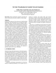
minimal number of messages to decide that all images are rendered and a minimal communication load on each node to minimize the delay between nodes. If communicational load is minimal at each node the number of collisions will be minimal too. The well known minimal spanning tree architecture [2] achieves the requirement of minimal number of messages to provide an information through a network of partially connected nodes. To avoid collisions in such networks we should use a small number of incoming and outgoing channels at each node. An architecture which combines features of the spanning tree and of nodes with a small number of incoming and outgoing channels will achieve both, minimal number of messages to decide that all clients are ready-todisplay and minimal number of collisions. Now we will discuss what minimal number of channels mean in our case. The minimal number of outgoing channels of a node to provide information to other nodes is one. The minimal number of incoming channels to receive information from the network is also one. The only topology for nodes with a single outgoing and incoming channel is a chain. This topology has a diameter of the number of nodes. For that reason it is not qualified for our case, because the skew of the distribution of synchronization-message is half of the diameter. Next choice of incoming channels is two. If every node has two incoming channels and one outgoing channel we can use a binary tree topology to order nodes. If the binary tree is balanced it is a minimal spanning tree for the nodes. For these reasons we use a balanced binary decision tree to arrive at the decision that all clients have rendered their views. At first the root of our binary decision tree can decide that all clients are ready to display. All other clients need more time to decide because the length of their paths to other nodes is longer than the paths to the root. The different length of that paths adds various delays to the decision at the different levels of the tree. To overcome these various delays we have to use an efficient communication protocol with minimal delay between all nodes to distribute synchronization-message. We use the binary tree only to collect information at the root and the root decides when to display rendered views. To distribute the decision to all other nodes we use a protocol with minimal delay. IP Multicast is a protocol that achieves the constraint of minimal delay between different nodes [10]. The decision architecture is shown in figure 1. This architecture has a very small delay for distribution of ready-to-display-information and synchronization message. Further on it reduces collisions on networks with parallel point to point connections as much as possible. The delay in switched ethernet with one switch for example is normally less than 120µsec [1] for one message and for IPMulticast.
Network architecture
Now we want to discuss the requirements of the network hardware. We want to design a scalable architecture, thus we assume in the following that we have only one physical bidirectional network interface at each node. An alternative approach is that every connection between a pair of nodes has it’s own physical network interface. But this is not scalable with standard hardware because one is only able to use a few interfaces at each host. Therefore we will describe the architecture as a logical network, which has to be mapped on the physical network. This means that all logical connections of one node are realized with one physical bidirectional connection. With above discussed requirements for the network hardware in mind we will treat the logical network structure in the following. The first possible choice of architecture might be a fully connected network architecture. But it isn’t a good choice because it produces very high network traffic since each node has to send messages to each other node. Another disadvantage of that architecture is the high delay between the decision of the first graphic client and the last one caused from network delay for sending messages to each other node sequentially. The use of IP Multicast can reduce this delay but often a noticeable delay caused from collisions will be left [10]. For this reason we need another network architectures which will be efficient in the number of sent messages and the delay after the decision that all clients are ready to display their rendered image. Today normally networks with the ability of parallel point to point connections, for example switched ethernet, are used. To use point to point networks optimally we need a decision architecture that has 3
root
information to our visualization network. This assumption is no constraint for interaction processing because if there is only one interaction process it is the interaction transmitter itself. For distributed interaction processing one process has to collect the relevant interaction information and transmit it to the visualization network. Tracking of user interaction does not depend on the frame rate of visualization because it can be continous interaction, for example pointing to an object at the display, or discrete interactions like clicking, selecting, etc. Especially interaction processing does not need to be synchronous to the frame rate of visualization. For this reason we assume interaction processing as asynchronous task. This assumption leads to a visualization network separated from the architecture for interaction processing. In this case it is possible to use every type of interaction processing algorithm. To correlate interaction events with the displayed context it is necessary to have a globally consistent time for visualization and interaction clients. For time synchronization of the clients clocks also NTP [21] can be used or for framewise synchronization the frame counter can be used.
multicast
rendering client
Figure 1. Architecture for decision and synchronization over network with 6 nodes: solid line for balanced binary tree used to transmit ready-to-display-message from graphics clients, dash dotted line for IP Multicast to transmit display-immedately-message with minimal delay.
In distributed environments it is necessary to have a globally consistant time stamp. One can use well known protocols like NTP [21] to synchronize system clocks. In the synchronized distributed visualization framework it is sufficient to have a globally consistent frame counter that takes the role of a relative time stamp. For this reason our protocol provides a frame counter with the synchronization message.
4.3
5.1
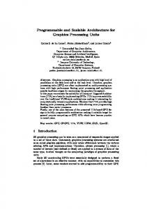
The interaction transmitter is a specific process not included in the visualization network. It communicates with the root of the visualization network and transmits all interaction data to the root. Furthermore, the interaction transmitter receives the frame counters which are distributed via multicast from the root of the visualization network. These frame counters can be used to correlate the interaction events with the displayed context. The root of the visualization process provides interaction information to all graphic clients together with the IPMulticast for synchronization. All graphic clients have to process this information for their context themselve. In this way every client can modify its state depending on interaction information. If this processing produces relevant information for other graphic clients it can be submitted as payload of the ready-to-display-messages to the root and will be transmitted to all other clients with the next synchronization-message. The modified architecture for visualization and interaction is shown in figure 2 This algorithm for interaction processing adds a delay to context modification by interaction. In the worst case we will have a delay of two frames. The aspects of quality-of-service criterion for interaction are discussed in detail by Holloway [6]. If the visualization has frame rates of 30 or more frames per second this interaction delay for most applications meets the quality-of-service criterion.
Extensions of the protocol
The protocol is open to extensions with existing rendering acceleration techniques. To reduce the need of specialized hardware for better rendering power it is possible to substitute our nodes in the protocol with WireGL driven clusters. In this way one may boost render power of each node with specific hardware while the synchronization between nodes can be done with standard components.
5
Interaction synchronization
Control of visualization network by interaction
In many virtual environments user interaction has to be processed. The above mentioned protocol for synchronization of graphic clients can be expanded to handle such interaction information. We will describe this extension for the protocol in this section. User interaction processing is a problem in it’s own and has been investigated in detail in last years but it is still a work in progress. The problem of distributed interaction processing is a current research topic [33, 31, 32, 29, 14]. There is a lot of research with focus on wireless networks for distributed interaction processing [4, 20, 22]. We assume that every type of interaction processing has one process (interaction transmitter) which is able to transmit interaction processing 4
root interaction data
number of levels 2 3 4
interaction transmitter
multicast visualization node
point to point
number of clients 2 6 12
sync-time in ms 100 MBit/s 1 GBit/s 0.129 0.39 0.386 0.70 0.616 -
Table 1. Measurement of time for synchronization with different number of levels of decision tree
Figure 2. Architecture vor visualization and interaction processing
until a certain number of packets have arrived or no packets have arrived for a certain period of time to avoid interrupt flooding. This is a tradeoff of latency for bandwidth.
6
Experimental results
6.2
To demonstrate the performance of our protocol, in this section we will measure the synchronization time delay throughout the network. Further on we will analyse the jitter2 of the displays. This is the resulting error of our protocol and the graphics hardware which has to be unnoticible for the users.
6.1
Jitter of displays
The jitter of the different displays can’t be measured directly on the network. To measure the jitter one has to use optical based techniques. For that reason we can determine only an upper bound for jitter of displays. The jitter of the displays ∆tdisplays depends on the jitter of the multicast ∆tmulticast of the network. This can be estimated by the difference between the minimal time for synchronization and the maximal time for synchronization (diff-sync-time) in one run. We consider the maximum of this time differences as an upper bound of network jitter for multicast. This upper bound is significantly larger than the real value of multicast jitter ∆tmulticast . The measurement of ∆tmulticast is shown in table 2. The jitter of displays also depends on the skew ∆tsync
Time delay for synchronization
The amount of time for synchronization (sync-time) of multiple clients varies in dependency of the number of clients, the number of levels in the balanced binary decision tree and on the network. We measure the time from sending ready-to-displaymessage to the protocol until the protocol returns with a synchronization-message without interaction payload. This time varies with the number of participating clients and resulting number of levels in the decision tree. We have measured this time for two clients (stereodisplay), six clients (CAVE) and twelve clients (stereo CAVE). The experiments were performed on two different networks, namely 100 MBit/s ethernet and 1 GBit/s ethernet. The binary decision tree in these cases has two levels for two clients, three levels in case of six clients and four levels for twelve clients. The measurements are shown in table 1. The level four with gigabit ethernet could not be measured since we had only 6 gigabit clients available. One can see the dependency of synchronization time with the number of decision tree levels for both networks. The overall time for synchronization is very small for all tested numbers of clients and networks. It is remarkable that the synchronization time for Gigabit ethernet is higher than for 100 MBit/s ethernet. This is caused by interrupt coalescing which is used in Gigabit ethernet devices. The idea behind interrupt coalescing is to wait before generating an interrupt
network 100 MBit/s 1 GBit/s
∆tmulticast in ms 4.2 1.9
Table 2. Difference between minimal and maximal synchronization time depending on network of the VSYNC3 signals of the different hosts. Since we can’t measure this time we use the time to display one video frame as an upper bound for ∆tsync . This upper bound depends on the video frame refresh rate of the display and not on the frame rate of the renderer and is usally less than 16 ms (video frame refresh rate of 75 Hz). The jitter of the displays ∆tdisplays is the sum of the multicast jitter ∆tmulticast and jitter of VSYNC ∆tsync . For the above mentioned reasons the skew of displays is less than 17.5ms for a video frame rate of 75 Hz and mostly effected by ∆tsync . This skew is un1 noticable for users because it is smaller than 50 second [27].
2 Jitter is a short-term variations of the significant instants of digital signals from their ideal positions in time.
3 Vertical Sync (VSYNC): portion of video signal that tells the receiver when to start a frame refresh.
5
6.3
Synchronization with payload
best performance. Our cluster contains four graphic nodes with 512 MB RAM and Nvidia Geforce 3 or Nvidia Geforce 2 graphics engine with 64MB memory. Our cluster drives a two sided stereo CAVE. In this way two nodes render the views of the left eye and the other two render the views of the right eye. To avoid visual artefacts we have to synchronize the visualization processes on the level of video frame buffer switching. We survey the video frame rate in case of unsynchronized
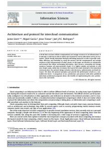
In the experiments described above we measured the synchronization time without interaction payload. We can also measure the dependency of payload size and synchronization time. These measurements are shown in figure 3. One can see that 100 MBit/s ethernet is linearly in payload 4.5 4
Render type
Sync-time [ms]
3.5 3
unsynchronized synchronized loss of frame rate
2.5 2 1.5
Table 3. Measurement of time for synchronization with different number of levels of decision tree
1 0.5
1000Base-T 100Base-T
0 0
5000 10000 15000 20000 25000 30000 35000 40000 45000 Payload Size [byte]
and in case of synchronized visualization. The loss in frame rate is denoted in percent. The results of unsynchronized and synchronized visualization are shown in table 3. One can notice that the frame rate decreases unnoticable to the user, as was the goal of our approach.
Figure 3. Synchronization time in dependence on payload size just as gigabit ethernet. The mean inverse gradient of each curve approximates the maximal transfer rate of the network. The peak in the curve for 100 MBit ethernet results from network load of other applications because we measure in a network with other loads like nfs filesystem, etc.The gigabit ethernet has a slightly higher delay with no payload due to interrupt coalesing, but better load performance. Therefore we can find a break even point between both networks at about 1 KByte per payload package. The above mentioned reasons suggest to use 100 MBit/s ethernet for purely synchronization or synchronization with small (less than 1 KByte) payload and to use gigabit ethernet for synchronization with larger payload.
6.4
Graphics engine Geforce 3 Geforce 2 148.4 fps 60.73 fps 144.0 fps 60.69 fps 2.9% 0.06%
7
Conclusions and future work
We have presented a protocol for distributed synchronized visualization and interaction. Our protocol in conttrast to the most existing protocols has no need for specialized synchronization hardware or network. Further on our protocol can handle interaction information to control context independent of the interaction processing architecture. The resulting jitter of displays is mostly effected by asynchronous graphics hardware and is unnoticeable for users.
References
Stereo rendering of 3D-scenes
[1] E. Ahlers. Datenverteiler: Zehn Switches f¨ur kleine Heimnetzwerke. c’t, (24):120ff, November 2001. [2] R. K. Ahuja, T. L. Magnanti, and J. B. Orlin. Network Flows: Theory, Algorithms and Application. Prentice Hall, February 1993. [3] I. Buck, G. Humphreys, and P. Hanrahan. Tracking Graphics State For Networked Rendering. In Proceedings of SIGGRAPH 2000, August 2000. [4] R. E. V. Dyck and L. E. Miller. Distributed Sensor Processing over an Ad Hoc Wireless Network: Simulation Framework and Performance Criteria. In Proceedings MILCOM 2001, October 2001. [5] E. Hart and J. L. Mitchell. Hardware Shading with In SIGEXT vertex shader and ATI fragment shader. GRAPH 2001 Real-Time Shading Course Notes, August 2001.
To demonstrate the performance of our protocol we have integrated it into the switch buffer command of OpenGL. In this way it is easy to integrate it into an existing OpenGL application. We extended the well kown OpenGL atlantis demo which can be found in the standard GLUT distribution [24]. Our version of the atlantis demo is extended by the use of fog, textured fishes and ground sea floor. Further on the modified switch buffer command of OpenGL is used to synchronize the visualization nodes. The payload in our case is 40 Bytes. We use the payload to transmit the global viewing transformation given by interaction and a type specifier for interaction information. We use 100MBit/s ethernet in this case of small payload to reach 6
[6] R. L. Holloway. Registration errors in augmented reality systems. Technical Report TR95-016, 1, 1995. [7] G. Humphreys, M. Eldrigde, I. Buck, G. Stoll, M. Everett, and P. Hanrahan. WireGL:A Scalable Graphics System for Clusters. In Proceeding of SIGGRAPH 2001, pages 129– 140, August 2001. [8] H. Igehy, G. Stoll, and P. Hanrahan. The Design of a Parallel Graphics Interface. In Proceedings of SIGGRAPH 98, pages 141–150, July 1998. [9] International Standard. ANSI/IEEE Std 802.3-1993, Standard for Information Technology, Protocols for Dristributed Interactive Simulation. Technical report, Institute of Electrical and Electronics Engineers, March 1993. [10] D. Ken. Issues Related to Multicast Groups. In The Eighth Workshop on Standards for Interoperability of Defense Simulations, pages 269–302, March 1993. [11] K. Lefebvre. An Exploration of the Architecture Behind HP’s New Immersive Visualization Solutions. [12] E. Lindholm, M. Kilgard, and H. Moreton. A User Programmable Vertex Engine. In SIGGRAPH 2001, August 2001. [13] M. Macedonia, M. Zyda, D. Pratt, P. Barham, and S. Zeswitz. NPSNET: A Network Software Architecture For Large Scale Virtual Environments. Presence, 3(4), Fall 1994. [14] V. Megalooikonomou and Y. Yesha. Quantizer design for distributed estimation with communication constraints and unknown observation statistics. EEE Trans. on Comm., 48(2):181–184, February 2000. [15] S. Molnar, M. Cox, D. Ellsworth, and H. Fuchs. A sorting classification of parallel rendering. In IEEE Computer Graphics and Algorithms, pages 23–32, July 1994. [16] J. Mortrym, D. Baum, D. Dignam, and C. Migdahl. InfiniteReality: A Real-Time Graphics System. In Proceedings of SIGGRAPH 97, pages 293–302, August 1997. [17] Myrinet. The Myricom network. Described at http://www.myri.com/myrinet/. [18] N. S. Naik. Experiences with an architecture for a distributed multimedia system. In IEEE Real-Time Systems Symposium, Workshop on Resource Allocation Problems in Multimedia Systems, December 1996. [19] B. Peters, C. Boyd, and J. L. Mitchell. Curved PN Triangles. In ACM Symposium on Interactive 3D Graphics, 2001. [20] G. Pottie. Wireless sensor networks. In Proceedings IEEE Information Theory Workshop, pages 139–140, June 1998. [21] N. T. S. Project. NTP. www.ntp.org. [22] A. Schmidt, K. Aidoo, A. Takaluoma, U. Tuomela, K. V. Laerhoven, and W. V. de Velde. Advanced interaction in context. In Proceedings 1st International Symposium on Handheld and Ubiquitous Computing (HUC99), 1999. [23] SGI. Multipipe. www.sgi.com/software/multipipe/. [24] SGI. The OpenGL Utility Toolkit. http://reality.sgi.com/mjk/#glut. [25] SGI. vizserver. www.sgi.com/software/vizserver/. [26] S. Singhal and M. Zyda. Networked Virtual Environments: Design and Implementation. Addison Wesley, 1999. [27] R. Steinmetz. Multimedia Technologie. Springer, 1999.
[28] G. Stoll, M. Eldridge, D. Patterson, A. Webb, S. Berman, R. Levy, C. Caywood, M. Taveira, S. Hunt, and P. Hanrahan. Lightning-2: A High-Performance Display Subsystem for PC-Clusters. In Proceedings of SIGGRAPH 2001, pages 141–148, August 2001. [29] Z. B. Tang, K. R. Pattipati, and D. L. Kleinman. Optimization of distributed detection networks: Part II generalized tree structures. IEEE Trans. Syst., Man Cybern., 23:211– 221, Jan./Feb 1993. [30] E. Teler and D. Lischinski. Streaming of Complex 3D Scenes for Remote Walkthroughs. In Proceedings EUROGRAPHICS 2001, volume 20, pages 16–25, September 2001. [31] S. C. A. Thomopoulos, R. Viswanathan, and D. K. Bougoulias. Optimal distributed decision fusion. In IEEE Trans. Aerospace Elect. Syst., volume 25, pages 761–765, September 1989. [32] J. N. Tsistsiklis. Decentralized detection. In Advances in Statistical Signal Processing, Signal Detection, volume 2, 1993. [33] R. Viswanathan and P. K. Varshney. Distributed detection with multiple sensors: Part I - fundamentals. In Proceedings of the IEEE, volume 85, pages 54–63, 1997. [34] I. Wald, P. Slusallek, C. Benthin, and M. Wagner. Interactive Rendering with Coherent Ray Tracing. In Proceedings EUROGRAPHICS 2001, volume 20, pages 153–164, September 2001.
7