Network service chaining with optimized network function embedding supporting service decompositions Sahel Sahhaf1 Wouter Tavernier1 Matthias Rost2 Stefan Schmid2,3 Didier Colle1 Mario Pickavet1 Piet Demeester1 1
Ghent University - iMinds
2
Technische Universit¨ at Berlin
3
T-Labs, Berlin
[email protected]
Abstract The rise of Software-Defined Networking (SDN) and Network Function Virtualization (NFV) introduces opportunities for service providers to reduce CAPEX/OPEX and to offer and quickly deploy novel network services. In particular, SDN and NFV enable the flexible composition of network functions, a generic service concept known as Network Service Chaining (NSC). However, the control of resources, management and configuration of network service chains is challenging. In particular, there typically exist multiple options on how an abstract network service can be decomposed into more refined, interconnected network functions. Moreover, efficient algorithms have to be devised to allocate the network functions. The underlying algorithmic problem can be seen as a novel generalization of the Virtual Network Embedding Problem (VNEP), where there exist multiple realization options. The joint optimization of decomposition and embedding has not been studied in the literature before. This paper studies the problem of how to optimally decompose and embed network services. In particular, we propose two novel algorithms to map NSCs to the network infrastructure while allowing possible decompositions of network functions. The first algorithm is based on Integer Linear Programming which minimizes the cost of the mapping based on the NSCs requirements and infrastructure capabilities. The second one is a heuristic algorithm to solve the scalability issue of the ILP formulation. It targets to minimize the mapping cost by making a reasonable selection of the network function decompositions. The experimental results indicate that considering network function decompositions at the time of the embedding significantly improves the embedding performance in terms of acceptance ratio while decreasing the mapping cost in the long run in both optimal and heuristic solutions. Keywords: Network Service Chaining (NSC), Network Function Virtualization (NFV), Software-Defined Networking (SDN), Network Function decomposition, embedding
Preprint submitted to Journal of Computer Networks
August 10, 2015
1. Introduction
5
10
15
20
25
30
35
40
45
Network Service Chaining (NSC) is a service concept which has gained much interest from both practitioners and researchers. NSC promises increased flexibility and cost-efficiency for future carrier networks. NSC is enabled by Software-Defined Networking (SDN) and Network Function Virtualization (NFV). Employing SDN and NFV developments simplifies the service chain provisioning significantly and enables the introduction of new services. Traditionally, a service composed of several functions is implemented by middleboxes and traffic should flow through these middleboxes in a given order. A service chain is an abstraction to define high-level services in a more generic way. The service is composed of a chain of high-level Network Functions (NFs) with pre-defined parameters referred to as Service Graph (SG). Different aspects of service chaining, its limitations and existing challenges are investigated by different activities and research projects such as: i) a dedicated working group (Service Function Chaining Working Group) in IETF which focuses on the service chaining architecture, ii) the Network Functions Virtualization (NFV) group within ETSI which investigates software-based telecommunications services to be run in virtualized environment instead of special purpose appliances, iii) UNIFY, an EUfunded FP7 project, which focuses on developing an automated, dynamic service creation architecture based on a dynamic fine-granular service chaining model leveraging Cloud virtualization techniques and SDN. An NF can be decomposed in multiple ways to several less abstract, more refined NFs, and thus an SG composed of several high-level NFs can be realized through multiple options referred to as service decompositions. To be more precise, NF decomposition refers to i) translation of a high-level/abstract NF (e.g., Firewall) to more refined NFs (e.g. an OpenFlow- or an iptables-based Firewall) or ii) decomposing a compound NF into multiple NFs which can potentially be abstract and are interconnected in a graph (e.g. a load-balanced Firewall can be decomposed into any number of Firewalls preceded by a number of load balancers). To give an example, consider that a user requests a service including a parental control NF. The functionality of this NF can be decomposed to i) Traffic Classifier, ii) Web Proxy and iii) Firewall NFs. Each of these NFs can be realized through more refined NFs, e.g. a Firewall can be implemented as i) iptables-based Firewall or ii) OpenFlow-based Firewall. These NFs should be traversed in a given order and the logical connectivity between them are as follows: Traffic Classifier → Web Proxy → Firewall. This connectivity can be represented by a graph which is referred to as a Network Function Graph NFG. Service decomposition is defined as a mapping of each NF into a set of NFGs: N Fi → {N F Gi1 , N F Gi2 , ...}. Having multiple decomposition options for service realization, a challenging task is to find an optimal placement of the NFs within the service to the components of an infrastructure. We refer to this problem as the Network Function Embedding Problem (NFEP) and Figure 1 illustrates its general idea. As we see in this figure, given multiple SGs composed of NFs and a common phys2
50
ical network, we look for a placement of NFs/logical links to the nodes/links of the physical network. In this figure, only one decomposition is depicted for each SG. However, as explained earlier, an SG can be realized through multiple decompositions. This problem can be seen as a generalization of the Virtual Network Embedding Problem (VNEP) in which virtual networks are mapped to a common infrastructure without having multiple realization options.
Figure 1: Network Function Embedding concept
55
60
65
70
75
The literature is rich on algorithmic proposals to solve the VNEP [1]. However, no work considered to decompose and embed an SG at the same time. Our contribution. The decompositions of an SG need to reflect required hardware resources and capabilities (e.g. requirement for iptables-based Firewall). Selecting a decomposition independently of available resources in the infrastructure may yield mapping solutions far from optimal. We accordingly present algorithms (optimal and heuristic) for the NFEP which take the SG decomposition opportunities into account. This would certainly improve the performance of the embedding as a reasonable decomposition is selected which corresponds to the existing resources and thus leads to a better placement of the NFs. To the best of our knowledge, the joint optimization of SG decomposing and its embedding has not been investigated in prior work. We first propose an Integer Linear Programming (ILP) model to solve the NFEP. This model considers SG decomposition options as the input of the embedding problem. The objective is to minimize the cost of the mapping based on the SG requirements and infrastructure capabilities. We define the cost of mapping an SG as the cost of the total substrate resources allocated to that SG which is calculated based on: i) the cost of each unit of CPU, memory and storage in a physical node ii) the cost of each unit of bandwidth in a physical link and iii) the resource usage of the given SG. The cost per unit of capacity (i,ii) is determined by the infrastructure provider (InP). The algorithm maps the NFs within an SG to the components of the physical network in such a way that the resource consumption is minimized and the QoS requirements of the SG are satisfied. This is proportional to maximizing the number of service requests which are accepted and thus the acceptance ratio in the long run is increased. One of the main constraints in this mapping is that NFs in an SG can be 3
80
85
90
95
100
105
of different types (e.g. a VM image, a process in a container or a hardware appliance). However, not all types, e.g., iptables-based and OpenFlow-based Firewalls, are supported by all infrastructure nodes. Solving the VNEP is NP-hard in most of the cases [2] and allowing for all possible SG decompositions generally increases the complexity drastically. As a result, finding the optimal solution might not be feasible in large-scale scenarios. We therefore propose a heuristic algorithm to overcome the scalability limitation of the ILP solution. In this scheme, first a reasonable decomposition is selected for the SG and then NFs of the selected decomposition are placed on physical network components based on a backtracking mechanism. This algorithm was briefly presented in [3] as a short paper, without any thorough evaluation. We use the proposed ILP-based approach to benchmark the heuristic algorithm. Therefore, this paper extends the work in [3] by providing an ILP model and a thorough evaluation of the proposed scheme. These evaluations should enable more accurate conclusions regarding the performance of the heuristic-based approach compared to the optimal solution. The proposed approaches are evaluated thoroughly and compared in an extensive computational evaluation. The experimental results indicate that employing SG decomposition options at the time of the embedding improves the performance of the embedding significantly in terms of acceptance ratio while decreasing the cost compared to scenarios in which a decomposition is selected independent of the available resources and NFs requirements. The rest of the paper is organized as follows: Section 2 explains the related work. Service decomposition is described in detail in Section 3. Section 4 describes the problem, and Section 5 details the proposed ILP model together with the ILP-based algorithm. The heuristic-based algorithm is explained in Section 6. Section 7 reports the performance evaluation results. Finally Section 8 concludes the paper. 2. Related work
110
115
120
The VNEP is known to be NP-hard [2] and therefore finding the optimal solution might not be affordable in large-scale scenarios (within reasonable time). As a result 2 different types of approaches are considered: i) Exact solutions which provide optimal solutions but are generally only applicable on smallscale problems, ii) Heuristic-based approaches which trade off optimality with runtime. Many of the algorithmic approaches to solve the VNEP have been detailed in the survey [1]. There are several proposals in the literature which formulate the VNEP as Integer Linear Programming (ILP) and find the optimal solution. In [4], the authors used ILP formulation to find a solution which minimizes the embedding cost and maximizes the acceptance ratio. Another ILP-based approach was introduced in [5] which focuses on minimizing the consumed resources in physical network to switch off the remaining resources of the network and save energy. Zhang et al. proposed an ILP model to achieve optimal resilient solution while satisfying the requested QoS requirements [6].
4
125
130
135
140
145
150
155
160
165
Dynamic reconfiguration of mappings and migrations were studied in [7] and Mixed Integer Programming was used to solve the problem. The literature on heuristic algorithms is much more diverse and ideas from very different fields have been considered. In [8] two heuristic-based approaches were presented. One focuses on minimization of resource consumption and the second one aims at load balancing. The same work proposed an ILP approach to benchmark the heuristic-based algorithms. In [9] VNEP is solved by a heuristic approach based on Subgraph Isomorphism Detection (SID) which maps nodes and links during same stage. Several heuristics focus on resiliency in the embedding which try to recover physical network failures [10, 11, 12]. Meta-heuristics such as ant colony optimization, simulated annealing, genetic algorithms or tabu search are used to find a close to optimal solutions. An example is the Max-Min Ant Colony meta-heuristic proposed in [13] to solve the VNEP. While the literature on the VNEP is very rich, the specific problem we attend to – namely of how to decompose and map an SG at the same time – was not considered before. Hence, we cannot use any previous work as baseline, but use our ILP to obtain one. Apart from the VNEP, the most closely related works are the following. In the work of Basta et al. [14] the function placement problem for LTE mobile core gateways is considered under different decompositions based on NFV and SDN. The function placement problem, which maps each of the (potentially decomposed) functions onto datacenters and establishes paths between the components is then solved according to the different decompositions. As shown in [14], depending on the chosen decomposition, the bandwidth usage and path latencies may vary to a great extent. This not only shows the benefits of combining NFV and SDN, but particularly, that it may be beneficial to decompose common complex functions. Mehraghdam et al. [15] consider the problem of embedding service chains under the relaxation that the order of NFs may be underspecified and NF A may be used before B or vice versa. Assuming that no restriction on the order of the NFs is given, this leads to n! many possible orderings for n NFs. The authors shortly discuss the computational complexity of finding the optimal ordering and argue for using a heuristic for choosing a good ordering. In [16], authors focus on NF placement for NFV chaining in packet/optical datacenters with the objective of minimizing the expensive optical/electrical/ optical (O/E/O) conversions. These conversions are needed because chaining within a ‘performance optimized datacenter’ (pod) is based on packet switching while between pods optical technologies are used. They try to minimize the O/E/O conversions by placing the NFs of the same chain in the same pod. They propose both a Binary Integer Programming formulation of the NF placement problem and an alternative heuristic algorithm. However, no notion of NF decomposition is considered in this paper. Abujoda et al. [17] proposed solutions for the discovery and selection of middleboxes along the traffic path. NFs composing a service chain are assigned to middleboxes, while preserving the order of the NFs as specified in the service chain. In their work, they address the challenge of flow processing establishment 5
Figure 2: Example of service decomposition
across multiple NF providers. 3. Service decomposition 170
175
180
185
The SG initially requested by a user is described by NFs and their logical connectivity. At this level the NFs might be either Elementary Network Functions (ENF) which means that their low-level implementation and resource requirements are available or abstract/Compound Network Functions (CNF) which means that they can be implemented through more refined NFs or they are composed of several ENFs. Service decomposition is the process of transforming an SG containing abstract NFs to SGs containing less abstract, more implementation-close NFs. Additionally, it refers to decomposing the functionality of a CNF into multiple less complex (potentially abstract) NFs interconnected in form of a graph with the same external interfaces as the abstract NF (see Figure 2). The main advantages of service decomposition are: i) re-usability of elementary blocks, ii) the possibility to generate new and more complex services and iii) the possibility to request services without any concern about the detailed implementation. These advantages simplify the network service chaining and provide opportunities for service providers to reduce the cost in CAPEX and OPEX.
6
190
An example service decomposition is illustrated in Figure 2. The high-level compound NF2 is decomposed to NF4 and NF5. Each of them can be decomposed to more elementary NFs (e.g., NF6, NF7,etc). These decompositions can be stored in a tree-like data structure in a database which is used by the embedding algorithms. Note that the leaves of this tree are elementary NFs for which all the resource demands and required low-level implementation are available. 4. Problem description
195
200
205
210
215
220
225
Service requests arrive over time and the embedding algorithm should decide whether the NFs within the requested SG and their corresponding connections can be mapped to the components of the physical network or not. Once requests are accepted, the required resources (physical links and nodes) are assigned and they are released once the requests expire. Elementary NFs within an SG can be of different types which means that they can be implemented in different ways using different techniques such as: i) Virtual Machine (VM) images using different virtualization techniques: VMware, VirtualBox, Xen, ii) hardware appliances, iii) process in a container or iv) packet I/O drivers, as e.g. Intel’s Data Plane Development Kit (DPDK)1 which is a set of libraries and drivers for fast packet processing. Having several types of NFs imposes additional constraints on the embedding problem because not all physical components of the network support all types. Additionally, interconnecting NFs of different types is more complex compared to interconnection of the NFs with the same type. For example it is more complicated to connect an NF which is a process in a container to a DPDK-based NF compared to the case in which both NFs are DPDK-based or both are the same-type processes in containers. To reduce this complexity, we prioritize an SG decomposition in which the number of same-type NFs which are directly interconnected is higher. In addition, such a prioritization i) reduces the amount of required resources, and ii) improves NF performance by reducing the communication overhead and latency. Prioritizing NFs of the same type enables mapping of more NFs to the same physical node; this leads to less network resource consumption as no physical links are used for the mapping. Interconnecting NFs over physical links implies additional communication and/or computational overhead due to e.g. additional tunneling requirements, which is not as high if NFs are located in the same physical node. In order to enable this prioritization, we define a parameter referred to as Cluster-Factor (CF ) which is calculated as follows for each decomposition: Given a service decomposition, the NFs with similar types which are connected directly (i.e., without intermediate nodes with other types) are grouped in the same cluster. The number of clusters in the decomposition determines the CF of that decomposition. Figure 3 illustrates two service decompositions with different CFs. As we see, in the decomposition at left, the Click-based NFs (NF1, 1 http://dpdk.org/
7
230
NF2 and NF3) are connected directly and thus are grouped in one cluster while NF4 which is a DPDK-based NF is placed in another cluster. Therefore, the CF of this decomposition is equal to 2. In the decomposition at right, although there are NFs with the same type (2 Click-based NFs: NF2 and NF4), they cannot be grouped in the same cluster because of the intermediate NFs (NF1 and NF3) which have different types. As a result each of the NFs is grouped in a different cluster and the CF of this decomposition is 4.
NF1 (click)
NF3 (click)
NF4 (DPDK)
NF1 (DPDK)
NF2 (click)
NF3 (VM)
NF4 (click)
NF2 (click)
CF=2
CF=4
Figure 3: Example of Clustering and CF in service decompositions
235
240
245
Our objective is to minimize the mapping cost of a given SG. This cost refers to the cost of the total substrate resources allocated to the SG which is calculated based on: i) the cost of each unit of CPU, memory and storage in a physical node ii) the cost of each unit of bandwidth in a physical link and iii) the resource usage of the given SG. The cost per unit of capacity (i,ii) is determined by the InP. Minimizing the mapping cost allows accepting more requests over time and increases the acceptance ratio. Acceptance ratio is a metric that measures the ratio of the accepted service requests which refer to services that are successfully mapped to the physical network. As service decompositions are known from the design time, we can make a resource-aware decomposition selection taking decompositions CF into account at the time of the embedding. 5. Integer Linear Programming formulation In this section, we introduce notations, variables, objective function and constraints which are used in the Integer Linear Programming formulation of the problem.
250
255
5.1. Physical network In the model, the physical infrastructure is represented as an undirected graph. The infrastructure consists of nodes (N) connected via links (L). Each node has certain capacity in terms of computation, memory and disk/storage, and links have delay and capacity in terms of bandwidth. These resources are actually the residual capacities based on previous mappings. Below we describe the parameters of the physical network infrastructure. Gp = (Np , Lp ) 8
Computation capacity (C), storage capacity (S) and memory capacity (M) with their corresponding unit cost are defined as follows: ∀u ∈ Np : Cu , Su , Mu ∈ N + ∀u ∈ Np : Ccostu , Scostu , Mcostu ∈ N + Each physical node can support different implementation types of NFs including: i) Virtual Machine (VM) images ii) process in a container iii) packet I/O drivers and iv) hardware appliances. Note that the model can simply be extended if other types of NF implementation are supported by the infrastructure nodes: ∀u ∈ Np : u ∈ VM, iff. u may host a VM ∀u ∈ Np : u ∈ process, iff. u may host a process ∀u ∈ Np : u ∈ I/O, iff. u may host packet I/O drivers ∀u ∈ Np : u ∈ hardware, iff. u has hardware appliances Propagation delay (D) and bandwidth capacity (BW) for physical links are described as follows: ∀euv ∈ Lp : Deuv , BWeuv , BWcosteuv ∈ N + 260
5.2. Service request As explained in Section 3, an SG can be realized through multiple decompositions. Therefore, for each SG there exists a decomposition set DecompSG . Note that this set contains all possible decompositions such that hierarchical decompositions are already ‘fully’ resolved. ∀SG : DecompSG = {dc1 , dc2 , ..., dcn }
265
Each decomposition is represented as a directed graph to support the dependency between different NFs. Therefore, the NFs in the decomposition are represented as nodes connected via the directed links in the graph. Each NF, has some requirements in terms of computation, memory and storage and links connecting different NFs have requirements in terms of delay and bandwidth. Gdc = (Ndc , Ldc ) The computation(c), memory (m) and storage (s) requirements of each NF (node) in the decomposition is defined as: ∀i ∈ Ndc : ci , si , mi ∈ N + Each NF can be implemented differently and thus can be of different type: ∀i ∈ Ndc : i ∈ {VM, process, I/O, hardware}
9
The maximum allowed delay (d) and bandwidth (bw) requirements of links in the decomposition are defined as: ∀eij ∈ Ldc : deij , bweij ∈ N + Finally each decomposition is assigned a Cluster Factor (CF) which is the number of clusters in the decomposition. The clusters in a decomposition include same-type NFs which are directly interconnected and can probably be mapped on the same physical node. ∀dc ∈ DecompSG : CFdc ∈ N + 5.3. Decision variables In our ILP model, different decision variables are required. The xiu is used to indicate if NF i independent of its type is mapped on physical node u. xiu ∈ {0, 1} ∀dc ∈ DecompSG , ∀u ∈ Np , ∀i ∈ Ndc The next variable is 1 if virtual link eij is mapped to physical link euv , and 0 if not. ij ∈ {0, 1} ∀dc ∈ DecompSG , ∀eij ∈ Ldc , ∀euv ∈ Lp feeuv The z dc variable is used to indicate if decomposition dc is selected for the mapping or not. z dc ∈ {0, 1} ∀dc ∈ DecompSG 5.4. Objective function
270
As explained in Section 4, the objective is to minimize the total cost of the mapping (i.e., the cost of the total substrate resources allocated to the given SG) while prioritizing the decompositions with lower CF and the advantages of this prioritization are: i) lower complexity in interconnection of NFs, ii) improving NF performance by reducing communication overhead and latency, and iii) reducing the compute and network resources. Minimize: X
X X
dc∈DecompSG u∈Np i∈Ndc
X
cost(i, u) +
X
X
cost(eij , euv )
dc∈DecompSG euv ∈Lp eij ∈Ldc
(1)
275
Below, we detail this objective function. In the rest of this paper, the notations ‘VM’, ‘PRC’, ‘I/O’ and ‘HW’ refer to different types of NFs (VM, process, I/O, hardware) explained earlier.
10
X
X
X
(ci ×Ccostu +si ×Scostu +mi ×Mcostu )×CFdc ×xiu +
dc∈DecompSG u∈Np(V M ) i∈Ndc(V M )
X
X
X
(ci ×Ccostu +si ×Scostu +mi ×Mcostu )×CFdc ×xiu +
dc∈DecompSG u∈Np(P RC) i∈Ndc(P RC)
X
X
X
(ci ×Ccostu +si ×Scostu +mi ×Mcostu )×CFdc ×xiu +
dc∈DecompSG u∈Np(I/O) i∈Ndc(I/O)
X
X
X
(ci ×Ccostu +si ×Scostu +mi ×Mcostu )×CFdc ×xiu +
dc∈DecompSG u∈Np(HW ) i∈Nd(HW )
X
X
X
ij (bweij × BWcosteuv × feeuv )
(2)
dc∈DecompSG euv ∈Lp eij ∈Ldc
280
285
290
Note that in this objective function, we multiplied the cost of the mapping by the CF . By this multiplication, it is ensured that the decompositions with lower CF are preferred over the decompositions with higher CF . As we see in the objective function, the sum over all the decompositions of the given SG is minimized. The reason is that all of these decompositions should be checked and the one which leads to minimum cost should be selected and mapped. In order to guarantee that only one decomposition is selected, we add several constraints which are detailed in Section 5.5.1. 5.5. Constraints There are different types of constraints which should be considered in the ILP formulation. We categorize them in 4 groups: i) decomposition constraints, ii) physical nodes, iii) link to path mapping and iv) QoS requirements. 5.5.1. Decomposition mapping constraints These constraints guarantee that only one of the decompositions of an SG is selected and all the NFs of the selected decomposition are mapped only once. X z dc = 1 (3) dc∈DecompSG
X
xiu = z dc
(4)
u∈Np(type)
∀dc ∈ DecompSG , ∀i ∈ Ndc(type) , ∀type ∈ {VM, PRC, I/O, HW}
295
5.5.2. Physical node constraints For each physical node, the sum of the requirements of all the mapped NFs should not exceed the capacity of that node. Therefore, we should add a constraint for each compute, memory and storage capacities while considering different types (constraints 5-7). 11
X
ci xiu ≤ Cu
(5)
i∈Ndc(type)
∀dc ∈ DecompSG , ∀u ∈ Np(type) , ∀type ∈ {VM, PRC, I/O, HW}
X
mi xiu ≤ Mu
(6)
i∈Ndc(type)
∀dc ∈ DecompSG , ∀u ∈ Np(type) , ∀type ∈ {VM, PRC, I/O, HW}
X
si xiu ≤ Su
(7)
i∈Ndc(type)
∀dc ∈ DecompSG , ∀u ∈ Np(type) , ∀type ∈ {VM, PRC, I/O, HW} 5.5.3. Link to path mapping When a link in the SG cannot be mapped to a single physical link, it should be mapped to a single path. In case of the latter, the link (or corresponding flow) in the SG cannot be split into several paths and thus no multipath is considered in the model. The next constraint makes sure that a simple unsplittable/single path for such a mapping is used. X X ij ij feeuv − feeuv = xju − xiu (8) euv ∈Lp ,u=src
euv ∈Lp ,u=dst
∀dc ∈ DecompSG , ∀eij ∈ Ldc , ∀u ∈ Np
300
5.5.4. Quality of service requirements For each physical link, the sum of the required bandwidth of all the links in each decomposition should not exceed the bandwidth capacity of the link. X ij bweij · feeuv ≤ BWeuv ∀dc ∈ DecompSG , ∀euv ∈ Lp (9) eij ∈Ldc
The next constraint guarantees that the sum of all physical link delays used for mapping a single virtual link in the service request does not exceed the maximum allowed delay in the request. X ij Deuv · feeuv ≤ deij ∀dc ∈ DecompSG , ∀eij ∈ Ldc (10) euv ∈Lp
305
As we used Integer Linear Programming formulation to solve the embedding problem, the model is limited to linear parameters. It can be extended with other parameters as long as they are linear. Note that parameters such as delay jitter and loss cannot be modeled through linear constrains and thus, 12
310
they are not considered in this model. It is worth mentioning that modeling such optimization problems as nonlinear programs to account for jitter and loss is hard but leads to high accuracy. However, such an accurate model requires very large computation which makes it impossible to solve the optimization problem in a reasonable time. 5.6. ILP-based algorithm
315
320
This algorithm implements the optimal ILP-based model which was detailed extensively in this section. The requests arrive over time and given all possible decompositions of an SG, the algorithm selects the decomposition which leads to minimum cost and embeds the corresponding NFs and logical links to physical network in such a way that the resource consumption is minimized. As a result, more requests can be embedded to the physical network and therefore, the acceptance ratio will increase in the long run [1]. The achieved embedding is based on the service requests constraints and the physical network limitations. The impact of considering service decompositions on different metrics such as acceptance ratio and mapping cost is evaluated in Section 7. 6. Decomposition Selection-Backtracking Mapping algorithm: DSBM
325
330
335
340
345
As the ILP-based algorithm has scalability limitations, we propose a heuristicbased approach which is referred to as DSBM [3]. Similar to any heuristic approach, the proposed scheme compromises optimality for short execution time. This algorithm comprises two phases: i) decomposition selection and ii) mapping. Given an SG and all possible decompositions in the first phase, we measure a cost corresponding to each decomposition and the one with minimum cost is selected. This decomposition is given as the input of the mapping phase and based on a backtracking mechanism a placement of the corresponding NFs and logical interconnections on the physical network are determined. These two phases are further detailed in this section. Decomposition selection. Given the physical network Gp , the service SG and all of its decompositions Decomp, the CF of each decomposition dc is calculated. As mentioned in Section 4, the objective is to prioritize a decomposition with lower CF and the advantage of this prioritization is twofold: i) the number of same-type NFs which are directly connected is more and thus their interconnection is less complex and ii) the more the number of NFs with the same type, the more NFs might be mapped to a same physical node and if they are directly connected, this leads to less network resource consumption as no physical links are used for the mapping. In addition, for each NF in a decomposition dc, the candidate physical nodes which can potentially host that NF are determined. A candidate physical node should support the NF type (VM, process, I/O or hardware appliance) and should have enough capacity to meet the requirements of the NF. We define parameter p to be the minimum number of candidate physical nodes for NFs of a dc. To have a concrete example, consider a service decomposition composed
13
350
355
of NF1 and NF2 which can be hosted potentially by 2 and 4 physical nodes respectively. Then p = min{2, 4} = 2. This parameter is defined to enable selection of a decomposition which is less restricting. It enables a resourceaware decomposition selection which means that a decomposition with NFs which can potentially be mapped to more physical nodes is selected. Such a decomposition enables embedding more service requests over time. We define a cost function which combines CF , p and n (with n being the number of NFs in a decomposition). C(dc) = a · 1/pdc + b · CFdc + g · ndc
360
In the decomposition selection phase of the algorithm, a decomposition with minimum cost C(dc) is selected. The parameters a, b and g are defined to tune the impact of different factors in the cost function. The pseudo code of this phase is illustrated in Algorithm 1. DecompositionSelection(Decomp) Data: service decompositions Decomp Result: minimum cost decomposition Cost=[]; for dc ∈ Decomp do CFdc = number of clusters; pdc = minimum (number of candidate physical nodes for NFs in dc); ndc = number of NFs; Cost(dc) = a.1/pdc + b.CFdc + g.ndc end select dc with minimum Cost(dc); Algorithm 1: DecompositionSelection pseudo code
365
370
375
Mapping. The selected decomposition dc in the first phase is given as the input of the mapping phase. In this phase, first the NFs of dc are clustered based on their types and their interconnection (this was explained for CF calculation). Then the clusters and the corresponding NFs are sorted based on their requirements in descending order. We start mapping the NFs of the cluster with maximum requirement. For each unmapped NF in the sorted list, all of its candidate physical nodes are sorted based on their distance (in terms of hop count) to the already used physical nodes in ascending order. This way we first check the physical nodes which are closer to the rest of the used nodes and thus, a lower number of physical links might be used for mapping of the logical interconnections. We select a physical node from the sorted list by which the logical links connected to the NF can also be mapped in the physical network. If none of the candidate physical nodes can provide such a mapping, the algorithm backtracks to the previous mapped NF and checks the next candidate. The pseudo codes for this phase are reported in Algorithms 2, 3, 4 and 5 which are detailed in the rest of this section. 14
ServiceMapping (dc) Data: selected decomposition dc cluster dc; sortedN F =sort clusters and their NFs based on their requirements in descending order; for N F ∈ sortedN F do candidate= sort the candidate nodes for N F based on their distance to the used physical nodes; i = 0; while MapNF(NF,candidate[i])==false do i+ = 1; if i ≥ length(candidate) then backtrack to previous mapped NF and select the next candidate in its sorted list; end end end Algorithm 2: ServiceMapping pseudo code
380
385
Given the selected dc, the ServiceMapping function clusters and sorts the NFs and the candidate nodes as explained above. It then tries to map the NFs of the dc one by one by invoking MapNF function. If all the candidate physical nodes are checked and the mapping of an NF is unsuccessful, it backtracks to previous mapped NF. The MapNF function, shown in Algorithm 3, checks that available resources such as CPU, memory and disk in the physical node are sufficient for hosting the NF. It then checks that all the connected links to the NF can be mapped to the physical network by invoking CheckLinks function. If it is successful in finding a mapping for all the links, the NF demands are reduced from the resources. MapNF(N F , pnode) if not enough capacity in pnode to map NF then return false; end success = CheckLinks(N F, pnode, mappedN odes); if success == true then mappedN odes+ = (N F, pnode); CP Upnode − = CP UN F ; M emorypnode − = M emoryN F ; Storagepnode − = StorageN F ; return true; end Algorithm 3: MapNF pseudo code
390
In the CheckLinks function, represented in Algorithm 4, it is checked
15
395
whether all the links connected to an NF can be mapped in the physical network. This function iterates over all the links adjacent to the NF and if the NF attached to the other side of the link was mapped, it checks if there is a path between the physical nodes used for the mapping of the NFs. The shortest path between the two physical node is considered. If such a path exists, it is checked for the QoS requirements. CheckLinks(N F , pnode, mappedN odes) for l ∈ links attached to NF do if neighbor attached to l ∈ mappedN odes then n= the physical node that the neighbor is mapped to; while true do path=shortest path between n and pnode; if path == N ull then return false; end success = CheckQoS(path); if success == true then for link ∈ path do BWlink − = BWl end end end end end return true; Algorithm 4: CheckLinks pseudo code
400
The CheckQoS function, shown in Algorithm 5, checks whether the QoS requirement of the logical link is satisfied by the given path. This function determines whether the bandwidth and delay requirements of the path are fulfilled. If all the above functions are successful a mapping for the requested service is found. 7. Performance evaluation
405
410
In this section we first describe the simulation environment and then the evaluation results are presented. The goal of the evaluations is to show the impact of the service decomposition choices on the resource footprint. The focus of the experiments is on quantifying the added value of considering service decompositions at the time of the embedding in terms of cost, acceptance ratio and cost/revenue ratio. In the simulations, we compare the heuristic-based approach with the ILP-based algorithm in network scenarios where ILP can be executed in reasonable time scale. We evaluate the effect of employing service decompositions in both schemes. The following approaches are compared in the evaluations: i) ILP-based algorithm, ii) DSBM algorithm, iii) ILP-based 16
CheckQoS(path) for link ∈ path do EndtoEndDelay+ = delaylink ; if EndtoEndDelay exceeds the constraint then remove the link from the network graph; return false; end if BWvirtuallink > BWlink then remove the link from the network graph; return false; end end return true; Algorithm 5: CheckQoS pseudo code
415
420
425
430
435
algorithm given one decomposition (random selection) and iv) DSBM given one decomposition (random selection). As there is no other approach which considers service decompositions in the embedding problem, we compared both DSBM and ILP-based algorithms with approaches in which decomposition is selected randomly. The latter refer to approaches in which one decomposition is selected randomly and it is mapped using DSBM or ILP respectively. With such comparison, we can clearly see the effect of a wise decomposition selection on the performance of the embedding. Table 1 presents the notations used for the compared approaches. In DSBM, we also evaluate the effect of different factors in C(dc) on the performance of the embedding by tuning a,b and g parameters. Furthermore, we report the execution time of both ILP-based and DSBM algorithms in different size physical networks to have an overview on the scalability of both approaches. 7.1. Simulation environment The simulation environment is based on Python code. Libraries such as Networkx and Numpy are used for graph-based and numerical implementations. PuLP is an LP modeler in Python which is used to generate the LP files and the ILP model is solved using the included Cbc solver (from COIN-OR2 ). For the physical network we considered two scenarios: i) small network scenario and ii) large network scenario. We used topologies from the Internet Topology Zoo 3 , which model real world ISP and backbone networks. These topologies are available in GML format. We have parsed these files and converted them to graphs in Networkx library in Python. For the small network, we considered the ‘BT Europe’ topology with 24 nodes and 37 edges. In the large network scenario, the ‘Interoute’ topology is used which is an international telecommunications service provider with the Europe’s largest cloud services 2 https://projects.coin-or.org/Cbc 3 http://www.topology-zoo.org/
17
440
445
450
455
460
465
470
platform. This network is composed of 110 nodes and 148 edges. For both scenarios, it is assumed that some of the nodes have general purpose servers supporting different virtualization technologies, and some of them have specific hardware appliances such as Firewall. This is selected randomly for the nodes. The CPU, memory and storage capacity of the nodes and bandwidth of the links are numbers uniformly distributed between 100 and 150 in both network scenarios. The cost of each unit of capacity is 1. As only propagation delay is considered in this paper, the delay of each physical link is selected proportional to the distance between the two attached nodes. In the selected topologies, nodes are annotated with their geographic coordinates (latitude and longitude). We used these coordinates to calculate the geographical distance between every two adjacent nodes and set the delay of the corresponding link accordingly. The resulting delays range between 1 and 30 time units. The parameters reflect the commonly chosen simulation setup in the VNEP literature (see e.g. [18]). The service requests arrive over time in a Poisson process with an average rate of 4 requests per 100 time units, each of which has a lifetime, exponentially distributed with an average of µ = 1000 time units. Each request can be realized with a few decompositions which is a number between 2 and 5 with uniform distribution. The number of NFs within each of the decompositions is a number uniformly distributed between 2 and 10. The CPU, memory and storage demands of each NF is a number with uniform distribution between 1 and 20. The NF types are assigned randomly. The bandwidth requirement of each link is a number between 1 and 50, uniformly distributed. The maximum allowed delay of each link is set to 1000 time units. Each pair of NFs within a decomposition is connected with probability 0.5. As a service graph is typically formed as a Directed Acyclic Graph with topologies such as a simple path or a forking path (see IETF drafts [19] on use cases for Service Function Chain), it is checked that: i) the generated decomposition graph is connected and ii) there is no cycle in the graph. The hardware used to run the simulation is Intel Xeon quad-core CPU at 2.40 GHz with 12 GB RAM. Each simulation scenario is iterated 10 times and the average over all the iterations is reported. 7.2. Performance metrics We measure the following performance metrics to evaluate and compare the proposed schemes:
475
• Execution time: This metric measures the time used by an scheme to find an embedding for a service request. • Acceptance ratio: It measures the ratio of the accepted service requests which refer to services that are successfully mapped to the physical network.
480
• Embedding cost: The embedding cost or mapping cost is equivalent to the cost of the total substrate resources used for mapping a service request. 18
Table 1: List of compared algorithms Notation ILP DSBM ILP-5 ILP-10 DSBM-5 DSBM-10 ILP-random DSBM-random
Algorithm description proposed ILP-based algorithm proposed heuristic-based algorithm ILP on SGs with 5 NFs ILP on SGs with 10 NFs DSBM on SGs with 5 NFs DSBM on SGs with 10 NFs ILP with random decomposition DSBM with random decomposition
Figure 4: Execution time of ILP and DSBM for SGs with 5 and 10 NFs. The 95% confidence interval of the reported average values is depicted.
485
In our evaluations, as the cost of each unit of capacity is set to 1, the embedding cost is equal to the total CPU, memory, storage capacity of nodes and bandwidth capacity of the links which are reserved for a service request.
490
• Embedding cost/revenue: This is the ratio between the embedding cost and the revenue of a service request. We define the revenue of a service request as the sum of the total resource demands of that request. In our evaluations, these demands are in terms of CPU, memory, storage requirements of the NFs and the required bandwidth in links.
495
500
505
510
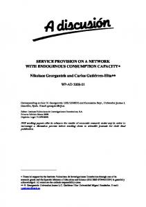
7.3. Evaluation results Before detailing the evaluation results on the two network scenarios explained earlier, we report the results related to the execution time of the proposed algorithms on different size physical networks ranging from 10 to 50 nodes to observe the scalability behavior of the schemes. The topologies were randomly generated and the service requests of two sizes, 5 and 10 were considered. Figure 4 depicts the execution time of different schemes. As expected, execution time of the ILP-based algorithm increases almost exponentially with the increase in the network size. This increase is more if the number of NFs in the service requests increases as well (see ILP-5 compared to ILP-10 in Figure 4). The heuristic-based approach scales significantly better and the execution time in DSBM-10 does not exceed a few 100 milliseconds. In the rest of this section, the simulation results for small network and large network scenarios are presented. The heuristic-based algorithm was scalable to large network scenario and leaded to similar conclusions in both scenarios. Due to scalability issues, the ILP-based approach was only evaluated in the small network scenario. We measured the average acceptance ratio, the corresponding embedding cost and the average cost/average revenue ratio for service requests over time. We report these performance metrics against time to indicate how different schemes perform in the long run.
19
1 . 0
Ac c e p t a nc er a t i o
Ac c e p t a nc er a t i o
1 . 0 0 . 8 0 . 6 0 . 4 0 . 2 0 . 0 0
I LP I LPr a n d o m DSBM DSBMr a n d o m
5 0 0 0
1 0 0 0 0 Ti me
1 5 0 0 0
0 . 8 0 . 6 0 . 4 0 . 2 0 . 0 0
2 0 0 0 0
(a) BT Europe network (24 nodes)
DSBM DSBMr a n d o m
5 0 0 0
1 0 0 0 0 Ti me
1 5 0 0 0
2 0 0 0 0
(b) Interoute network (110 nodes)
5 0 0 4 5 0 4 0 0 3 5 0 3 0 0 2 5 0 2 0 0 1 5 0 1 0 0 5 0 0
I LP I LPr a n d o m DSBM DSBMr a n d o m
5 0 0 0
1 0 0 0 0 Ti me
1 5 0 0 0
Ave r a gec os t
Ave r a gec os t
Figure 5: Service request acceptance ratio over time. The shaded background behind each curve represents the 95% confidence interval on the reported average values.
2 0 0 0 0
(a) BT Europe network (24 nodes)
5 0 0 4 5 0 4 0 0 3 5 0 3 0 0 2 5 0 2 0 0 1 5 0 1 0 0 5 0 0
DSBM DSBMr a n d o m
5 0 0 0
1 0 0 0 0 Ti me
1 5 0 0 0
2 0 0 0 0
(b) Interoute network (110 nodes)
Figure 6: Average cost of accepting requests over time. The shaded background behind each curve represents the 95% confidence interval on the reported average values.
515
520
525
530
Figure 5 depicts the service acceptance ratio for 4 different approaches in the two network scenarios: i) ILP, ii) DSBM, iii) ILP-random and iv) DSBMrandom. In both network scenarios, the results indicate significant improvements in terms of acceptance ratio in the proposed ILP-based and heuristicbased algorithms compared to approaches in which a random decomposition is selected. The acceptance ratio of DSBM is higher in the Interoute network compared to the results in BT Europe which is the result of having more resources in the network. In DSBM the parameters in the C(dc) function are set as follows: a = 0.25, b = 0.25 and g = 0.5. These parameters are tuned experimentally to achieve a reasonable performance. The effect of each factor in C(dc) function on the embedding performance is evaluated and reported later in this section. The average embedding cost in the 4 explained approaches are presented in Figure 6. Comparing the proposed schemes and the ones with random decomposition selection, we observe a significant difference in the average cost of the embedding. Both ILP-random and DSBM-random consume more resources compared to ILP and DSBM respectively. Additionally, the results indicate that the ILP-based solutions lead to almost constant average costs while the heuristic solutions result in decrease of the embedding cost in the long run. The reason for such a behavior is explained by the optimality of the embedding solution. In 20
Ave r a gec os t / Ave r a geRe ve nue
Ave r a gec os t / Ave r a geRe ve nue
1 . 1 0 1 . 0 5 1 . 0 0 0 . 9 5 0 . 9 0 0 . 8 5 0 . 8 0 0 . 7 5 0 . 7 0 0
I LP I LPr a n d o m DSBM DSBMr a n d o m
5 0 0 0
1 0 0 0 0 Ti me
1 5 0 0 0
2 0 0 0 0
(a) BT Europe network (24 nodes)
1 . 1 0 1 . 0 5 1 . 0 0 0 . 9 5 0 . 9 0 0 . 8 5 0 . 8 0 0 . 7 5 0 . 7 0 0
DSBM DSBMr a n d o m
5 0 0 0
1 0 0 0 0 Ti me
1 5 0 0 0
2 0 0 0 0
(b) Interoute network (110 nodes)
Figure 7: The ratio between average cost and average revenue over time. The shaded background behind each curve represents the 95% confidence interval on the reported average values.
535
540
545
550
555
560
DSBM, due to sub-optimal placement of the service requests, less requests can be accepted in the long run (presented in Figure 5). Furthermore, as there are less available resources in the network compared to when an optimal placement is found, the service requests with less NFs can be accepted. This leads to a decrease in the average embedding cost over time. This behavior is also visible in the Interoute network for DSBM-random approach which is less efficient than DSBM. Revenue gives an insight into how much an infrastructure provider (InP) will gain by accepting a service request however, it is not useful without considering the cost the InP will incur for mapping that request. Therefore, in the next figure, we report the ratio between average cost and average revenue in different schemes. Figure 7 depicts the results for different approaches in the 2 network scenarios. Note that the smaller this ratio, the more efficient the scheme is. This means that for mapping a request, fewer resources are used compared to the gained revenue. However, this metric should be considered together with the acceptance ratio to enable a better conclusion regarding the efficiency of the schemes. An efficient scheme should have high acceptance ratio with low cost/revenue ratio. In Figure 7, ILP leads to the lowest ratio while ILP-random has the highest one. Both DSBM and DSBM-random lead to very similar ratios. DSBM performs slightly better compared to DSBM-random which is more noticeable in the Interoute network. As we see, this ratio is even higher than 1 for DSBM-random at the beginning which is the indication of the poor performance considering the very low acceptance ratio. Next, we report the effect of different factors in the C(dc) function of DSBM on the embedding performance. Figure 8 illustrates the service request acceptance ratio when only one of the 3 factors in C(dc) is considered for decomposition selection. Such an evaluation gives an idea on how to tune the parameters (a, b and g) in C(dc) to have a more efficient embedding. Based on the results, considering the number of NFs in a request leads to higher acceptance ratio compared to cases when only CF (b = 1) or p (a = 1) are considered. The last two cases result in very similar performance. The related average embedding 21
1 . 0
Ac c e p t a nc er a t i o
Ac c e p t a nc er a t i o
1 . 0 0 . 8 0 . 6 0 . 4 0 . 2 0 . 0 0
a=1 , b=0 , g=0 a=0 , b=1 , g=0 a=0 , b=0 , g=1
5 0 0 0
1 0 0 0 0 Ti me
1 5 0 0 0
0 . 8 0 . 6 0 . 4 0 . 2 0 . 0 0
2 0 0 0 0
(a) BT Europe network (24 nodes)
a=1 , b=0 , g=0 a=0 , b=1 , g=0 a=0 , b=0 , g=1
5 0 0 0
1 0 0 0 0 Ti me
1 5 0 0 0
2 0 0 0 0
(b) Interoute network (110 nodes)
Figure 8: Service request acceptance ratio over time in DSBM. The shaded background behind each curve represents the 95% confidence interval on the reported average values.
3 5 0
a=1 , b=0 , g=0 a=0 , b=1 , g=0 a=0 , b=0 , g=1
3 0 0 2 5 0
Ave r a gec os t
Ave r a gec os t
3 5 0
2 0 0 1 5 0 1 0 0 0
5 0 0 0
1 0 0 0 0 Ti me
1 5 0 0 0
2 5 0 2 0 0 1 5 0 1 0 0 0
2 0 0 0 0
(a) BT Europe network (24 nodes)
a=1 , b=0 , g=0 a=0 , b=1 , g=0 a=0 , b=0 , g=1
3 0 0
5 0 0 0
1 0 0 0 0 Ti me
1 5 0 0 0
2 0 0 0 0
(b) Interoute network (110 nodes)
Figure 9: Average cost of accepting requests over time in DSBM. The shaded background behind each curve represents the 95% confidence interval on the reported average values.
565
570
cost is presented in Figure 9 and as expected, selection of decompositions with less number of NFs leads to lower cost compared to the other two cases. Figure 10 illustrates the ratio between average cost and average revenue in DSBM when only one of the factors in C(dc) function is considered. In both networks, when only number of NFs in a request is considered in the C(dc) calculation (i.e., g = 1), higher ratio is achieved. This was expected as this factor is used to select the smaller service decompositions which lead to decreased revenue. Looking at both acceptance ratio and the ratio between average cost and average revenue, considering one single factor is not efficient enough and thus a combination of these factors is required in the decomposition selection phase to have a low-cost embedding with high revenue and high acceptance ratio. 8. Conclusion
575
A network service chain consisting of several network functions can often be realized in multiple ways, as there are multiple options on how to decompose a high-level network function into several less abstract network functions. The process of converting a service chain with abstract network functions to 22
Ave r a gec os t / Ave r a geRe ve nue
Ave r a gec os t / Ave r a geRe ve nue
1 . 1 1 . 0 0 . 9 0 . 8 a=1 , b=0 , g=0 a=0 , b=1 , g=0 a=0 , b=0 , g=1
0 . 7 0 . 6 0
5 0 0 0
1 0 0 0 0 Ti me
1 5 0 0 0
2 0 0 0 0
(a) BT Europe network (24 nodes)
1 . 1 1 . 0 0 . 9 0 . 8 0 . 7 0 . 6 0
a=1 , b=0 , g=0 a=0 , b=1 , g=0 a=0 , b=0 , g=1
5 0 0 0
1 0 0 0 0 Ti me
1 5 0 0 0
2 0 0 0 0
(b) Interoute network (110 nodes)
Figure 10: The ratio between average cost and average revenue over time in DSBM. The shaded background behind each curve represents the 95% confidence interval on the reported average values.
580
585
590
595
600
service chains with more refined network functions is referred to as service decomposition. In this paper, we proposed two novel approaches to use service decompositions at the time of service embedding: i) an ILP-based algorithm and ii) a heuristic-based algorithm composed of two phases: decomposition selection and backtracking-based mapping. The heuristic-based approach solves the scalability limitation of the ILP-based algorithm at the cost of less efficient embeddings. The algorithms minimize the resources consumed to map a service request on a physical network while fulfilling service QoS requirements. As a result, more services can be mapped over time and the service acceptance ratio increases in the long run. Importantly this work is different from other existing works in the sense that both service decomposition selection and the embedding are solved at the same time. The proposed approaches were evaluated thoroughly in a simulation environment and were compared with approaches in which decompositions were selected independent of their demands and available resources in the network. The experimental results indicate that significant improvements in terms of acceptance ratio and mapping cost can be achieved if service decompositions are employed at the time of the embedding and a reasonable selection is made. Additionally, simulation results have shown that unlike the ILP-based algorithm, the heuristic-based approach DSBM is scalable and can be used in large-scale networks, where waiting for the optimal solution is prohibitive. Acknowledgment This work was conducted within the framework of the FP7 UNIFY project and is partially funded by the Commission of the European Union and partly funded by the UGent BOF/GOA project ‘Autonomic Networked Multimedia Systems’ .
23
605
References [1] A. Fischer, J. F. Botero, M. Till Beck, H. De Meer, X. Hesselbach, Virtual network embedding: A survey, Communications Surveys & Tutorials, IEEE 15 (4) (2013) 1888–1906.
610
[2] R. McGeer, D. G. Andersen, S. Schwab, The network testbed mapping problem, in: Testbeds and Research Infrastructures. Development of Networks and Communities, Springer, 2011, pp. 383–398. [3] S. Sahhaf, W. Tavernier, D. Colle, M. Pickavet, Network service chaining with efficient network function mapping based on service decompositions, in: 1st IEEE Conference on Network Softwarization, NetSoft 2015, 2015.
615
620
[4] I. Houidi, W. Louati, W. B. Ameur, D. Zeghlache, Virtual network provisioning across multiple substrate networks, Computer Networks 55 (4) (2011) 1011–1023. [5] J. F. Botero, X. Hesselbach, M. Duelli, D. Schlosser, A. Fischer, H. De Meer, Energy efficient virtual network embedding, Communications Letters, IEEE 16 (5) (2012) 756–759. [6] X. Zhang, C. Phillips, X. Chen, An overlay mapping model for achieving enhanced qos and resilience performance, in: Ultra Modern Telecommunications and Control Systems and Workshops (ICUMT), 2011 3rd International Congress on, IEEE, 2011, pp. 1–7.
625
630
[7] G. Schaffrath, S. Schmid, A. Feldmann, Optimizing long-lived cloudnets with migrations, in: Proceedings of the 2012 IEEE/ACM Fifth International Conference on Utility and Cloud Computing, IEEE Computer Society, 2012, pp. 99–106. [8] A. Hammad, R. Nejabati, D. Simeonidou, Novel methods for virtual network composition, Computer Networks 67 (2014) 14–25. [9] J. Lischka, H. Karl, A virtual network mapping algorithm based on subgraph isomorphism detection, in: Proceedings of the 1st ACM workshop on Virtualized infrastructure systems and architectures, ACM, 2009, pp. 81–88.
635
640
[10] H. Yu, C. Qiao, V. Anand, X. Liu, H. Di, G. Sun, Survivable virtual infrastructure mapping in a federated computing and networking system under single regional failures, in: Global Telecommunications Conference (GLOBECOM 2010), 2010 IEEE, IEEE, 2010, pp. 1–6. [11] W.-L. Yeow, C. Westphal, U. C. Kozat, Designing and embedding reliable virtual infrastructures, ACM SIGCOMM Computer Communication Review 41 (2) (2011) 57–64.
24
[12] G. Sun, H. Yu, L. Li, V. Anand, H. Di, The framework and algorithms for the survivable mapping of virtual network onto a substrate network, IETE Technical Review 28 (5) (2011) 381–391. 645
650
655
660
[13] I. Fajjari, N. Aitsaadi, G. Pujolle, H. Zimmermann, Vne-ac: Virtual network embedding algorithm based on ant colony metaheuristic, in: Communications (ICC), 2011 IEEE International Conference on, IEEE, 2011, pp. 1–6. [14] A. Basta, W. Kellerer, M. Hoffmann, H. J. Morper, K. Hoffmann, Applying NFV and SDN to LTE mobile core gateways, the functions placement problem, in: Proceedings of the 4th workshop on All things cellular: operations, applications, & challenges - AllThingsCellular ’14, ACM Press, New York, New York, USA, 2014, pp. 33–38. doi:10.1145/2627585.2627592. URL http://dl.acm.org/citation.cfm?doid=2627585.2627592 [15] S. Mehraghdam, M. Keller, H. Karl, Specifying and placing chains of virtual network functions, in: Cloud Networking (CloudNet), 2014 IEEE 3rd International Conference on, IEEE, 2014, pp. 7–13. [16] M. Xia, M. Shirazipour, Y. Zhang, H. Green, A. Takacs, Network function placement for nfv chaining in packet/optical datacenters, Journal of Lightwave Technology 33 (8) (2014) 1565–1570. [17] A. A. P. Papadimitriou, Midas: Middlebox discovery and selection for onpath flow processing, in: 7th International Conference on COMmunication Systems and NETworkS, COMSNETS 2015, 2015.
665
[18] N. M. K. Chowdhury, M. R. Rahman, R. Boutaba, Virtual network embedding with coordinated node and link mapping, in: INFOCOM 2009, IEEE, IEEE, 2009, pp. 783–791. [19] W. Liu, H. Li, O. Huang, M. Boucadair, N. Leymann, Z. Cao, Q. Sun, C. Pham, Service function chaining (sfc) general use cases, Tech. rep., Internet-Draft draft-liu-sfc-use-cases-08 (2014).
25