INTERNATIONAL JOURNAL OF NETWORK MANAGEMENT Int. J. Network Mgmt 2008; 18: 147–158 Published online in Wiley InterScience (www.interscience.wiley.com) DOI: 10.1002/nem.675
Network virtualization under user control Omar Cherkaoui*,† and Elbiaze Halima Université du Québec à Montréal (UQAM), Montréal, Québec, Canada
SUMMARY In this paper, we present the main challenges for offering end-to-end virtual network services under user control. This work is motivated by the growing need for end-to-end virtual services to support high-volume data transfer applications such as large data Center, grid applications and storage area networks over multi-domain networks. The virtualization of network services has to deal with some important issues, such as dynamic provisioning, sharing control, isolation and security. We have developed and implemented a solution called user control Virtual Service that allows the user to deploy and share different virtual services over a multi-domain network. UCVS is a network-driven virtual service solution that enables the coordinated provisioning and reuse of physical and virtualized computing, storage and network resources from shared pools. UCVS ensures that applications are dynamically supported throughout multi-domain infrastructure. UCVS also achieves cross-technology orchestration, helping further progress towards a service-oriented infrastructure. Copyright © 2008 John Wiley & Sons, Ltd.
1. INTRODUCTION With the growth of electronic commerce and the huge deployment of servers, the demands of virtualized services are rising. In order to overcome flexibility, scalability, manageability and mainly isolation issues in traditional IT infrastructure, virtual network services like virtual private networks (VPNs) and virtual local area networks (VLANs) are constructed to emulate the characteristics of a private network in public networks. A great effort was made by the network community and many projects, such as GENI and CA*net4, have started building the next-generation network mainly based on the virtualization concept. At the end of the 1960s, the virtual machine monitor (VMM) came into being as a software abstraction layer that partitions a hardware platform into one or more virtual machines. Each of these virtual machines was sufficiently similar to the underlying physical machine to run existing software unmodified. At the time, general-purpose computing was the domain of large, expensive mainframe hardware, and users found that VMMs provided a compelling way to multiplex such a scarce resource among multiple applications. Thus, for a brief period, this technology flourished both in industry and in academic research. Virtualization allows isolation and heterogeneity to function independently and effectively without being intrinsically tied to the network layer. There is a different kind of virtualization in the network. Many network features such as interface, LAN, link, router and network are now offered as new services: VLAN, virtual interface, VPN, virtual link, virtual Router, etc. The Internet is relatively resistant to fundamental change. We are realizing now that the Internet is not the panacea to satisfy the future needs for network management, and that the challenges ahead require
*Correspondence to: Omar Cherkaoui, Université du Québec à Montréal (UQAM), Case postale 8888, Montréal, Québec H3C 3P8, Canada † E-mail:
[email protected]
Copyright © 2008 John Wiley & Sons, Ltd.
148
O. CHERKAOUI AND E. HALIMA
a radical revision of the principles of the architecture of network management of communication. These new network services are mainly hard to manage. Interaction between them and other physical services is also difficult to deal with. Virtual services are becoming more frequent especially in research communities (e.g., bandwidthintensive e-science applications). These applications require the transfer of high volumes of data such as GridFTP, bioinformatics and storage area networks (SANs). To use core network resources efficiently, one should empower multi-gigabit user applications with dynamic service provisioning. In other words, users or applications need to flexibly control the provisioning of virtual services such as VPNs across multiple independent ISPs. Note that the users/applications are in a better position than providers to select and manage resources adapted to their needs, for example in order to build VPNs. The dynamically provisioned resources in network service virtualization incur many more challenges such as consistency, multi-ISP networks and equipment heterogeneity. Hence, we present in this paper a new network virtualization paradigm called UCSV, in which applications receive virtual services from a number of suppliers and control them independently, i.e., to establish, tear down, concatenate and share virtual services according to their needs. Our experimentation results have shown that UCVS service virtualization is efficient for relatively long-duration applications (up to 30 min). In these cases, the ratio of virtual service creation time to application duration time is still acceptable. This paper is organized as follows. Section 2 describes the network virtualization concept and highlights the main challenges for realizing UCVS. Section 3 describes the UCVS architecture and gives details about using UCVS for service virtualization. Test and implementation of UCVS in CA*net4 are illustrated in Section 4. Finally, concluding remarks are given in Section 5.
2. NETWORK VIRTUALIZATION Virtualization is not a new concept for the network community. First developed for the computer community, IBM in the mid 1960s developed virtualization specifically for mainframe computers. Currently, there are a number of virtualization techniques available—hardware and software approaches—each of which addresses different issues. 2.1 Network virtual service
During the past 10 years telecom operators having adopted Internet Protocol (IP) as the heart of the network and have sought to develop new services on IP in order to migrate legacy services (ATM-PVC, frame relay) over the IP network. New concepts like Site, Customers EDGE, CP and CE, and many services like VLAN, VPN and Optical Virtual Private Network (OVPN), have been defined and deployed over the 10 ten years. One of the most used one is network service virtualization. VLANs were the first virtual services offered in the network. Thereafter, the services of VPN mainly based on protected tunnels (IPsec, etc.) were very popular. The Internet Engineering Task Force (IETF) have started two working groups (L2vpn and L3VPN), whose goal consists in standardizing these new services operators [1–5]. Virtual Private LAN Service (VPLS) is a service that emulates LAN across an IP and a Multi-Protocol Label Switching (MPLS)-enabled IP network, allowing standard Ethernet devices to communicate with each other as if they were connected to a common LAN segment. They also proposed a Virtual Private Wire Service (VPWS) L2 service that provides L2 point-to-point connectivity (e.g., frame relay DLCI, ATM VPI/VCI, point-to-point Ethernet) across an IP and an MPLS-enabled IP network [6,7]. Another popular virtual service is the virtual router (VR). A VR has exactly the same functionalities as a physical router, and therefore can inherit all existing mechanisms and tools for configuration, deployment, operation, troubleshooting, monitoring and accounting. Multiple VRs can exist in a single physical device. Today, this service is offered by many types of equipment. Copyright © 2008 John Wiley & Sons, Ltd.
Int. J. Network Mgmt 2008; 18: 147–158 DOI: 10.1002/nem
NETWORK VIRTUALIZATION UNDER USER CONTROL
149
2.2 Need for multi-domain service
The need to provide end-to-end service provisioning motivates the consideration of end-to end virtual service provisioning. The applications carrying data originate from higher application layers and are provisioned from access networks over metro and backbone networks. In this scenario applications require an end-to-end virtual provisioning service, which requires knowledge of different levels of virtualization and various administrative domains within the network. Each domain may be characterized by its topology, routing policy and granularities within the domain, and transport policies. The notion of level of virtualization is referred to the case where the service goes through multi-layer networks which can have different virtualization services. The notion of multi-domain refers to the case where the service goes through various administrative domains [8]. 2.3 Needed operations for virtualization
To establish a end-to-end virtual service over a multi-domain network, the user can select virtual services from the providers and create his own new service. For this purpose, we have proposed and developed different operations such as concatenation and sharing. 3. USING UCVS FOR VIRTUALIZATION UCVS can very simply be thought of as a configuration and partition manager that exposes each link in a physical network and each network element associated with a link as an ‘object’ or ‘service’ that can be put under the control of different network users to create their own logical IP network topologies [8]. UCVS has many similar objectives to the one proposed in the GENI [9] program, specifically in regard to the concept of network virtualization. The major difference between these concepts is that UCVS assumes that there is no predefined canonical network architecture. Rather, the user is given the tools to build any desired variation of virtual (and real) network architecture on top of one or more substrates across different ownership domains. This user-defined network can be packet or switched and the user decides what type of topology, restoral, protection and routing may be necessary for their particular requirements. In essence, the future network architecture has no predefined network architecture. Instead, a substrate is provided which is capable of supporting many separate user-defined networks which can be assembled through a series of ‘Lego block’ type web services. UCVS allows for a creation of a set of VPNs (L1VPN [10]) which can be configured into a topology decided upon by the user, including meshes, rings, etc. UCVS also allows the user to reconfigure the topology of this mesh of VPNs and change their shape, size and path, and hence create ‘articulated’ private networks (APNs). APNs are similar in many ways to the GENI concept of many virtual networks sharing a common network substrate linking together virtual instruments, routers and devices. With APNs all the virtual links and devices are represented as web services and are linked together via web service workflow tools, as described in more detail in the following section. In GENI there is as yet no defined process for creating virtual links and connecting them to virtual devices and/or time slices. By representing the substrate, child links, switches, routers and time slices or processes, the user with UCVS has complete flexibility and control to architect the resulting network in way they wish to use web service workflow tools. 3.1 UCVS design assumptions and criteria
UCVS is a technology that operates on the layer below any protocol that operates on the network topology discovery and routing layer. UCVS is intended to be a user-controlled configuration protocol that allows users such as ISPs, enterprises and, in some cases, individual users to set up direct network virtual services. Copyright © 2008 John Wiley & Sons, Ltd.
Int. J. Network Mgmt 2008; 18: 147–158 DOI: 10.1002/nem
150
O. CHERKAOUI AND E. HALIMA
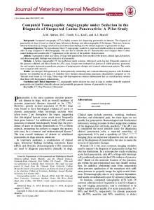
Figure 1. UCVS network virtualization
As mentioned previously, UCVS is akin to a partition manager, but with much more functionality and extensibility. Once network elements and links have been partitioned, the respective owners of those partitions may elect to implement their choice of network topology discovery and routing protocol. So rather than one topology discovery and routing plane there may be several parallel topology discovery and routing planes, each with independent topologies and routing protocols. As such, with UCVS there is no primary requirement in terms of traditional IP routing to support routing, topology discovery, reservation, scheduling, authorization, accounting or other related services. However, variations of these services are largely implemented in the current versions of UCVS not so much to support traditional IP routing but to enable partition management applications. It is expected that most of the network functionality will be provided by higher-layer services operating above the partition layer. It should be noted that some links owners may want to operate a routable VPN (APN) where the links, rather than the packets, are rerouted in the event of a link failure. In that case link status information needs to be delivered to the UCVS partition owner in order that the switches in that partition can reroute the links (see Figure 1). However, in most cases it is assumed that a partition owner will run and maintain a set of layer 3 routing, topology and fail-over daemons or protocols to provide such services between the partitions on different switches which are under the control or ownership of that specific partition owner. These routing daemons may be a logical router or a blade router that is integrated with the switch. It is the subsequent partition owner’s layer 3 routing protocol that determines link failures, rather than depending on the underlying switch or optical fabric to report outages. It is important to note that a user may have ownership of partitions on switches that are in different physical network domains. As such, the user must run their own keep-alive or hello messages between each link to detect link or node failure, as well as provide restoral and protection services if required. Copyright © 2008 John Wiley & Sons, Ltd.
Int. J. Network Mgmt 2008; 18: 147–158 DOI: 10.1002/nem
NETWORK VIRTUALIZATION UNDER USER CONTROL
151
The underlying physical network providers will have no visibility or awareness of the other networks and cannot provide such a capability. Finally, it should be pointed out that UCVS can operate on a physical switch or a virtual abstraction of a physical switch. It is not necessary that a network operator exposes and partitions all their network switches and links within their network. Instead they can offer a ‘virtual’ UCVS service through a userto-network interface. To the end user the network cloud appears as single switch entity, but in fact the ‘cross-connects’ across the virtual switch may in fact be facilitated through the creation of edge-to-edge VPNs across a network cloud. In reality, this is likely to be the most common way for network operators to provide ‘intra-domain’ UCVS services. 3.2 Architecture overview
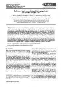
Current network architecture perspectives are largely proscribed by the network layer stack model where each network layer only communicates with the layer above and below it and is largely hidden from the end user. However, another view is that the network is less of a layered set of services, but more akin to a software service, conceptually like the Unix ‘pipe (|)’ command. The Unix pipe command is a utility that links the output of one software program to the input of another. This concept can now be applied to network services where the network is a software utility that allows data to be piped from one application to another. Exposing all network links as individual web services would enable this concept of Unix piping in the wider area not only between end points but also between traditional network layers. By viewing everything as a service from the traditional application layer to the physical layer new relationships and linkages can be established between applications, users and networks. End-to-end service scenario We describe hereafter a scenario of UCVS architecture for end-to-end Virtual Network Service (VNS) provisioning over multiple Autonomous Systems (ASes). AS administrators build up in advance local VNS services which traverse one or more ASes and put them into a common VNS repository called a VNSO Registry (VNS Object Registry). The establishment of an end-to-end VNS consists of first looking into the VNSO repository for local services, and then concatenating them to create the end-to-end VNS. Figure 2 illustrates the different steps of the end-to-end VNS setup. To limit the search space, the Border Gateway Protocol (BGP) ASes path is referred to as the route of ASes across which the end-to-end
Figure 2. End-to-end service Copyright © 2008 John Wiley & Sons, Ltd.
Int. J. Network Mgmt 2008; 18: 147–158 DOI: 10.1002/nem
152
O. CHERKAOUI AND E. HALIMA
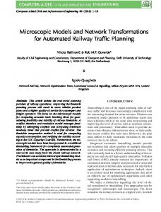
service should pass through. In each AS, there are some dedicated modules for managing services and for controlling the service provisioning. The unused end-to-end virtual resources may be advertised in the same manner, and other users can use them to build their own services. UCVS architecture is built for multi-domain networks. An end-to-end service is a concatenation of a number of interconnected compatible single-domain VNSs. The compatibility of local (single-domain) VNSs consists of respecting a set of pre-established rules such as links bandwidth matching and neighboring. A single-domain service starts from an interface of the ingress router of a domain and terminates on an interface of the egress router of the same domain. The end-to-end resource reservation consists of a set of single-domain resource reservations and, similarly, the end-to-end resource setup consists of a set of single-domain resource setups. The QoS guarantee for an end-to-end VNS is naturally satisfied when all essential single-domain resources are reserved. The architecture encompasses the following layers: • The inter-domain layer is responsible for the reservation of end-to-end resources by requesting single domain resources from domains and concatenating them. • The intra-domain layer is in charge of the resource reservation and setup inside a domain. It is also responsible for checking the conformance of resource requests with the domain admission rules. • The device layer acts directly on the domain network devices. This layer allows the upper layers to be independent from the operating system of the network devices. The interactions between layers or domains are realized by using web services. APN service scenario UCVS permits ISPs to create ‘discipline’- or ‘application’-specific Layer 1 VPN or IP networks which would create separate high-speed networks for these specific applications. As opposed to traditional VPNs the UCVS allows end users to do their own traffic engineering, change the topology of their collection of VPNs, and cross-connect their collection of VPNs over multiple domains to VPNs operated by other users, as shown in Figure 3. In this example we see an APN created from three separate independent managed domains and, in turn, a ‘child’ APN has been created out of the multi-domain APN. The nodes can be either virtual routers or switches. The nodes indicating that they have been partitioned indicate that control of the virtual router or switch has also been handed over to the owner of the APN or child APN, whichever the case may be.
Partitioned Node Pass Through Node
Child APN
Multi-Domain APN
Domain A
Domain B
Domain C
Figure 3. Creation of APN from multiple independent managed domains Copyright © 2008 John Wiley & Sons, Ltd.
Int. J. Network Mgmt 2008; 18: 147–158 DOI: 10.1002/nem
NETWORK VIRTUALIZATION UNDER USER CONTROL
153
This scenario creates a logical level to avoid direct access to the network equipment. The network resources are advertised as web services. It provides (i) a generic inventory process that can run on heterogeneous networks and (ii) a user-friendly graphical GUI, (iii) open interfaces to integrate any application on it easily and (iv) a unique and original orchestration tool that enables one to pre-configure and create new services and finally semantically validate the workflows. The APN scenario is composed of three main components: the domain administrator, the APN manager and the end user. In what follows, we present details about each element. • Domain administrator. The domain administrator manages the resources of the domain. The main role of the domain administrator is to create APN manager accounts and associate them with roles. The domain administrator is also responsible of the domain resources advertising. He can decide which resource should be advertised to third parties and associate these resources to some specific policies. • APN manager. The APN manager is authorized to create APNs and advertise them from the resources list advertised by the domain administrator. He is responsible of managing the resources published in his APN. Managing the resources consists of associating the APN’s resources with some specific end users; i.e., the APN manager can create APNs from some advertised resources in CA*net4, and can then create some users accounts and associate them with some of the APN’s resources. The architecture provides useful operations to APN managers to update the advertised resources to their needs. • End user. The end user is the final consumer of the service. Once authorized by the APN manager, the end user can select some resources from the APN and create a service. For that purpose, the architecture enables end users to manipulate VNSOs (concatenation, sharing, etc.). Hence, end users can adapt the published resources to their needs. Note that each one of the above-mentioned elements is associated with a user profile. The profile describes the resources and services that the user is authorized to use. The authorization can be done through ownership; for example, the APN manager can discover advertised resources (link, interface, etc.), and decide to own them. The APN manager allows the end user to get some links and interfaces from his APN. The profile enables the actor to have an idea about the resources he can use. If a resource does not appear in the user profile, that means that the user should find it (discover the resource) in the local and/or another domain and add it to its profile.
4. IMPLEMENTING UCVS VIRTUALIZATION IN CA*NET4 4.1 Advantages of virtualization in CA*net4
To make the use of the network resources more efficient and flexible, we adopt the virtual topology concept. The virtualization in our work consists of representing the physical resources in a logical format and encapsulating all information requiring a solid technical background (framing types, topology, equipment type, commands syntaxes, etc.). The virtualization enables separation of the physical level and the logical level by abstracting the interaction complexity with equipment and configurations. Concretely, the virtual topology is a list of logical objects representing the physical resources (interfaces, optical links, network segments, etc.) and can be manipulated by authorized users/applications to create their own connections. However, users do not have direct access to the network equipment or real physical topology. Here we present the advantages of this virtualization concept (see Figures 4 and 5): • Efficient use of network resources. In the virtual topology concept, end users/applications do not access the physical resources directly. On the other hand, they access the logical objects that enable manipulation of the physical resources. While the logical objects encapsulate the necessary information to Copyright © 2008 John Wiley & Sons, Ltd.
Int. J. Network Mgmt 2008; 18: 147–158 DOI: 10.1002/nem
154
O. CHERKAOUI AND E. HALIMA
Figure 4. Initial logical topology
Figure 5. Modified logical topology
configure the physical resources, end users will use easily preconfigured connections which avoid wrong manipulation of the advertised physical resources. • Flexible and optimized use of network resources. The virtualization concept enables one to reconfigure the discovered topology and adapt them to our needs. The logical resources provide a list of operations that enable users/applications to modify their encapsulated configuration (bandwidth, end points, etc.), which modify the logical topology and optimize the use of physical resources. To illustrate this concept, consider the following example. User can discover an OC3 optical link (155.52 Mbps) between Montreal and Toronto, then partition it to three OC1 (51.84 Mbps) optical links. So rather than using the initial link, the user will reserve only one OC1 optical link. In that case the logical topology initially provides one link between Montreal and Toronto, and after partitioning the logical object that presents the physical link, the logical topology changes and provides three OC1 links between Montreal and Toronto. • Simple use of network resources. With the expansion of optical networks in the metropolitan and campus networks, end users become one of the main consumers of these resources. Most end users do not have any technical background that enables them to manipulate optical switches and/or understand the necessary keywords to activate an OVPN. With the virtualization concept, the logical object must advertise the necessary information for end users to search and select the needed resources that fulfill their requests. It is easy for an end user to deal with source, destination, bandwidth, and lease duration information rather than having direct access to the switches to select the slots, ports, STS channel number, framing type, etc. By implementing the virtual topology concept, end users/applications can self-provision and configure the networks by themselves and the entire technical configuration will be completely transparent for them. 4.2 Virtual topology concept in UCVS
UCVS implements the virtual topology concept by providing logical objects in order to illustrate the local domain’s physical resources: OVPN Object and Articulated Private Network. Copyright © 2008 John Wiley & Sons, Ltd.
Int. J. Network Mgmt 2008; 18: 147–158 DOI: 10.1002/nem
NETWORK VIRTUALIZATION UNDER USER CONTROL
155
Figure 6. OVPN object level versus physical resources level
The domain administrator advertises the physical resources as OVPN Objects. The list of OVPN Objects represents one or multiple virtual topologies that end users/can discover and manipulate them. The virtual topology represents the logical level that end users/applications can use to create their services. In UCVS, the virtual topology can illustrate the domain resources or an APN. Figure 6 shows how UCVS separates between the physical resources level and the logical level, also called the OVPN Objects level. As shown in Figure 6, the OVPN Object level is composed only of OVPN Objects. The OVPN ObjectEdmontonToFredirecton-1-12 represents a list of physical interfaces. The interface configuration is hidden inside the OVPN Object description. The physical topology is also abstracted in the OVPN Object level; the users see the resource as a link between Edmonton and Fredericton and does not care about the physical path. In this case, to create an OVPN between Edmonton and Fredericton, the end user will have to activate the OVPN Object, without caring about the physical path or interfaces (slot number, sub-slot, port number, STS#, etc.) list to configure. UCVS implements the logical topology concept for the following reasons: • Advertise different topology from one physical topology: based on the users’ authorizations, the system builds for each user a profile that defines the role of the user and the resources that he can use. With the virtual topology, the system creates a virtual topology for each user. All the OVPN Objects and/or APNs will constitute the OVPN Object level that the user will manipulate. • Modify the advertised resources for an optimized use of the physical resources: while users have access to the OVPN Object level, they can apply operations to the selected OVPN Objects or APNs in order to adapt the advertised resources to their needs or activate them to create OVPNs. • Hide the real topology for security aspects: the virtual topology concept enables the domain administrator to hide the physical topology of their network. Users only have access to the OVPN Object level, so they cannot have an idea about the equipment, path, or interfaces they are using to activate a logical resource. 4.3 OVPN Object and APN logical resources
UCVS should deal with the different resources provided by optical networks such as CA*net4. In our implementation we define two types of resources: resources and web services. Web services represent the services provided by the UCVS to instantiate and manipulate the resources. In fact, UCVS is services-oriented architecture where the resources are instances of web services. These web services are directly reachable through URLs by the GUI or other applications such as orchestration applications. In this section we define all the resources that are manipulated by UCVS. OVPN Object The first resource we describe in this document is the OVPN Object. In our approach the OVPN Object represents a physical resource in the network. For example, the OVPN Object could be the optical link between Montreal and Halifax in CA*net4. Copyright © 2008 John Wiley & Sons, Ltd.
Int. J. Network Mgmt 2008; 18: 147–158 DOI: 10.1002/nem
156
O. CHERKAOUI AND E. HALIMA
OVPN Objects are instantiated in our system by the OVPN ObjectService. Authenticated and authorized users can manipulate the OVPN Object through a list of advertised operations. The OVPN Object resources and operations are described through a published WSDL that describes the OVPN Object instance (identifier, bandwidth, etc.) and also the applicable operations (concatenation, sharing, etc.). For example, if the user wants to activate an OVPN Object, he should invoke the deploy OVPNObject() operation. The OVPN Object is of two different types: 1. Link. This is the virtual channel between two remote interfaces. 2. Interface. This indicates the ingress or egress of the OVPN. In UCVS an interface is composed of: • Node name. The switch identifier in the network. • Slot number. The slot identifier in the switch. • Port number. The port identifier in the slot. • STS#. The STS channel number (optional in some cases). The OVPN ObjectService provides the necessary operations that enable modification of the virtual topology by changing the advertised LPOs. The main operations are sharing and concatenation. Sharing OVPN Object OVPN ObjectService provides the sharingOVPNObject() operation to enable users adapting the discovered OVPN Object to their specific needs in terms of bandwidth. To ensure a good optimization of use of resources, the sharing operation enables users to partition their OVPN Object into smaller OVPN Objects (i.e., inheritance), which may then be advertised to other users or used for another purpose. The process of dividing the OVPN Object is recursive. That is, the owner of an OVPN Object may grant access to a portion of its initial OVPN Object to another user, who in turn can share it with another user (leasing a portion of the OVPN). Figure 7 illustrates the sharing process. Concatenation Concatenation operation enables users to extend the OVPN Object to pass through several nodes to reach a far destination. Knowing that the OVPN Object is an object in the primitive state that illustrates the link between two or more (a list of physical interfaces) adjacent interfaces, the OVPN Object extension consists of a concatenation of neighbor OVPN Objects. This function is recommended to enhance the performance of the creation of an OVPN Object. In fact, in UCVS, we create an OVPN Object from one or multiple OVPN Objects. While creating an OVPN from a list of OVPN Objects can take more time to validate each OVPN Object, extract the configuration of each OVPN Object, etc., we can concatenate the OVPN Objects that we expect to use to create the same OVPN. Figure 8 shows how the concatenation operation could extend OVPN Object. UCVS provides also unShare and unConcatenate operations to reverse the result of sharing and concatenation operations.
Figure 7. Sharing OVPN Object Copyright © 2008 John Wiley & Sons, Ltd.
Int. J. Network Mgmt 2008; 18: 147–158 DOI: 10.1002/nem
NETWORK VIRTUALIZATION UNDER USER CONTROL
157
Figure 8. Concatenation of two OVPN Objects
Articulated Private Network (APN) In our approach the APN represents a segment of an optical network. For example, the APN could represent the network segment Montreal to Halifax resources in Ca*net 4. We cannot compare APN to OVPN, as far as the APN is a resources list that can be used to create an OVPN. For example, APN Manager can create an APN from a logical topology, advertised in his profile, and select a list of OVPN Objects to create an APN. The APN Manager can authorize an end user to access the new APN and use it to create an OVPN. The APNs are instantiated in our system by the APNService. Authenticated and authorized users can manipulate the APN through a list of advertised operations. The APN resources and the operations are described through a published WSDL that describes the APN instance (identifier, URL, ResourcesList, etc.) and also the allowed operations (getResourcesList, getAPN, advertise, etc.).
5. CONCLUSION Virtual services are becoming more frequent, especially in research communities (e.g., bandwidth-intensive e-science applications). Those applications require the transfer of high volumes of data such as GridFTP, bioinformatics and storage area networks (SAN). To use core network resources efficiently, one should empower multi-gigabit user applications with dynamic service provisioning. In other words, users or applications need to flexibly control the provisioning of virtual services such as VPNs across multiple independent ISPs. Note that the applications are in a better position than providers to select and manage resources adapted to their needs, for example in order to build a VPN. The dynamically provisioned resources in network service virtualization incur much more challenges such as the consistency, multi-ISP networks and equipment heterogeneity. We presented in this paper a new network virtualization paradigm called UCSV where applications receive virtual services from a number of suppliers and control them independently, i.e., to establish, tear down, concatenate, and share virtual services according to their needs. Our experimentation results [11,12] have shown that UCVS service virtualization is efficient for relatively long-duration application (up to 30 min). In those cases, virtual service creation time to application duration time ratio is still acceptable.
REFERENCES 1. Layer 3 Virtual Private Network (L3VPN) Working Group. http://www.ietf.org/html.charters/l3vpn-charter. html. [6 February 2008] 2. Provider Provisioned Virtual Private Network (PPVPN) Working Group. http://www.ietf.org/html.charters/ OLD/ppvpn-charter.html. [6 February 2008] 3. Virtual Private Network Consortium (VPNC). http://www.vpnc.org [29 October 2007]. 4. Carugi M, McDysan D (eds). Service Requirements for Layer 3 Provider Provisioned Virtual Private Networks (PPVPNs). RFC 4031, April 2005. 5. Callon R, Suzuki M. A framework for Layer 3 Provider-Provisioned Virtual Private Networks (PPVPNs). RFC 4110, July 2005. 6. Muthukrishnan K, Malis A. A core MPLS IP VPN architecture. RFC 2917, September 2000. 7. Rosen E, Rekhter Y. BGP/MPLS IP Virtual Private Networks (VPNs). RFC 4364, February 2006. Copyright © 2008 John Wiley & Sons, Ltd.
Int. J. Network Mgmt 2008; 18: 147–158 DOI: 10.1002/nem
158
O. CHERKAOUI AND E. HALIMA
8. Prevelakis V, Jukan A. How to buy a network: trading of resources in the physical layer. IEEE Communications Magazine 2006; 44(12): 94–102. 9. NSF Initiative GENI. http://www.geni.net/ 10. Takeda T, Aubin R, Inoue I, Carugi M. Layer 1 virtual private networks: service concepts, architecture requirements, and related advances. IEEE Communications Magazine 2004; 42(6): 132–138. 11. Truong DL, Cherkaoui O, Elbiaze H, Aboulhamid M. A policy-based approach for user controlled lightpath provisioning. In IEEE/IFIP NOMS, 19–23 April 2004, Vol. 1; 859–872. 12. Hallé S, Villemaire R, Cherkaoui O, Tremblay J, Ghandour B. Extending model checking to data-aware temporal properties of web services. In 4th International Workshop on Web Services and Formal Method. Lecture Notes in Computer Science, Vol. 4184. Springer: Berlin, 2007.
AUTHORS’ BIOGRAPHIES Halima Elbiaze received the BS degree in Applied Mathematics from the University of Rabat, Morocco, in 1996. She received the MS and Ph.D. degrees in Computer Science from the University of Versailles, France, in 1998 and 2002, respectively. She is currently a Professor in the Department of Computer Science, University of Quebec in Montreal, Canada. Her research interests are in the area of Quality of Service, performance evaluation and traffic engineering for high speed networks (IP/WDM, TCP/IP, ATM, FR, etc.). Omar Cherkaoui received a Ph.D. degree in computer science in 1990 from the University of Montreal and is currently a Professor and a director of the Teleinformatics Laboratory at the University of Quebec in Montreal. His research interests include network management (standardization, protocols, configuration, validation, modelling, testing), optical networks, etc. He was member of the technical program committees of a dozen network management conferences (IM, NOMS and DSOM, etc.).
Copyright © 2008 John Wiley & Sons, Ltd.
Int. J. Network Mgmt 2008; 18: 147–158 DOI: 10.1002/nem