dNT is used for neurons of assembly K6. Now, let us analyze the loops RTH1 and RTH2. In order to construct these loops the following vectors are added:.
2013 BRICS Congress on1st Computational BRICS Countries Intelligence Congress & on 11th Computational Brazilian Congress Intelligence on Computational Intelligence
Neural Assemblies and Finite State Automata João Ranhel Department of Electronic and Systems UFPE – Universidade Federal de Pernambuco Recife, Brazil jranhel @ ieee.org
Abstract—Neural assembly computing (NAC) is a framework for investigating computational operations realized by spiking cell assemblies and for designing spiking neural machines. NAC concerns the way assemblies interact and how it results in information processing with causal and hierarchical relations. In addition, NAC investigates how assemblies represent states of the world, how they control data flux carried by spike streaming, how they create parallel processes by branching and dismantling other assemblies, how they reverberate and create memory loops, among other issues. As cell coalitions interact they realize logical functions. Memory loops and logical functions are the elements engineers use to create finite state machines (FSM). An overview of NAC is provided, a methodology for implementing FSM in NAC is presented in this paper, a finite state automaton is designed, and a simulation and respective results are shown. Supplemental materials are available for download. Discussions about how FSM on NAC and how NAC itself can contribute for designing new types of spiking neural machines are presented.
are also pointed out. In Section VI, conclusions are presented. II.
Keywords—Neural assembly computing, cell ensembles, finite state machines, neural coalition, finite-state automaton.
I.
INTRODUCTION
Neural assembly computing (NAC) is an approach that tries to explain how neural cell ensembles represent and compute. The idea behind this framework is somehow simple: neurons represent internal/external objects and ‘states of the world’ by means of cell assemblies. Interactions among these coalitions perform logical functions (AND, OR, NOT), and assemblies may form reverberating loops which memorize information just like flip-flops in digital circuits. Logical gates and flipflops are the elements engineers use to construct computers, finite state machines (FSM), among other electronic systems. Hence, in NAC the tools, knowledge, and technical procedures used in digital systems projects are used to design spiking neural networks (SNN). The NAC approach was introduced in [1], and constructions of FSM (or finite-state automata, FSA) using NAC is discussed in this article. In section II, the concept of cell assembly is revisited, the biological inspiration and plausibility are also discussed. In Section III an overview of NAC is shown. Section IV presents a revision on the FSA concepts and how FSAs are related to biological systems. A methodology for designing FSA in NAC is introduced. Simulations and the results that support claims made in the paper are also presented. The Section V holds discussions on how FSA in NAC can help on developing new classes of SNN. Directions for further investigations on NAC 978-1-4799-3194-1/13 $31.00 © 2013 IEEE DOI 10.1109/BRICS-CCI-CBIC.2013.16 10.1109/BRICS-CCI.&.CBIC.2013.12
NEURAL ASSEMBLIES AND COMPUTING
The idea that groups of neurons (instead of single cells) represent, memorize, and underlie brain processes is relatively old. In 1949, in “The organization of Behavior” [2], D. Hebb proposed that concepts are represented by the activity of partially-overlapping neural groups, and the co-activation of ‘cell assemblies’ could be responsible for representing things. A formalization of the cell assembly concept can be found in [3], where Wickens and Miller idealized a small block of homogeneous cortex tissue with local connections and used realistic physiological and anatomical parameters in order to determine the relationship for governing neural assembly ignitability, the number of strengthened synapses needed to produce a spike in a single neuron member, the upper and lower limits of neural assembly size, the capacity for independent activation, among other arguments. The model implicitly considers the idea of ‘digital coalitions’, once the authors consider that there is a fraction of assembly’s members which, once triggered, inevitably makes all the assembly to ignite [3]. In their conception, after reaching a threshold in the number of active members, the assembly operates in an all-or-none fashion. Other authors describe assemblies by using more informal descriptions, for example, in the same sense relating coalitions to spatiality: “[Assembly:] A spatially distributed set of cells that are activated in a coherent fashion and are part of the same representation” [4]. However, other descriptions take assembly as “transiently active ensembles of neurons” [5] independently of their spatial position or their neighboring relations. This is how coalitions are considered in NAC. Functionally speaking, since a neural group fires together it forms a coalition and the neurons do not have to be located at the same spatial region. So far, investigations in NAC consider mainly digital coalitions. Digital assemblies (DA) are neural groups in which the coalition’s behavior is determined by the great majority of their members [1]. A DA is a set of cells working in a dual-state manner: all (or almost all) neuron members firing together, or none of them firing for that assembly. However, individual neurons may be active for other assemblies out of a specific-assembly time window, or it may simply fire due to noise. Thus, whenever a group behaves like an ‘active’ or ‘inactive’ coalition it is considered as a DA. 28
Sometimes spikes from an assembly A or from an assembly B can independently trigger a third assembly C. It means that A OR B is able to trigger C. This is equivalent to the logical function OR (denoted by the Boolean notation C ← A + B, which is read C is caused by spikes from A or from B). In other situations, spikes from A (associated to the synaptic weights A→C) are not strong enough for triggering C alone, and the same may occur for spikes coming from B (and the synaptic weights B→C) to C. But, when spikes from A AND B occur coincidently they become strong enough for triggering C. It means that this interaction performs the logical function AND (in Boolean notation C ← A x B, which is read C is caused by spikes from A and B simultaneously). What is meant by ‘strong enough’ is: if the synaptic weights from A and B are sw/2 only the spike coincidence from both A and B is strong enough for causing Θ, which triggers each neuron on the coalition C. One who knows Boolean algebra and digital circuits may be confused because, for the AND function, the inputs A AND B must remain active high (logic level ‘1’) in order to obtain the output C high, but spiking neurons fire only for a brief instant, in general | 1 ms. This is an important point: an assembly executes a logical function (AND, OR) only during the ephemeral time the coalition is happening. After that the resulting spikes simply become ‘travelers’ to other nodes. Therefore, NAC machines may be seen as ‘flux’ machines, in which information is most of the time travelling along axons. As the reader can infer, A can singly trigger other assembly, and an event A can also trigger (cause) more than one assembly, a process called branching. Each new branch is a parallel process triggered into the SNN. Now consider that an event (a smell, a vision, a pain, etc) creates an assembly. It means that assembly ‘represents’ that event. Considering that coalitions stand for something (they represent external or internal states of the world), nervous systems should not let such ephemeral events disappear once they might carry important information. Therefore, nature probably found a way for retaining information by using assemblies. In other words, cell coalitions must interact in order to retain important representations, events, states, etc. The solution can be reverberation among assemblies: an assembly A may trigger an assembly B that may trigger A back forming a loop. Simple loops performing binary counters were shown in [13]. However, it is possible that loops are much more complex, such as A triggers B that triggers C that triggers D that triggers A back, or even more complex (see [1]). These reverberating loops are called Bistable Neural Assemblies (BNA) because they can be on two states: ON (active) or OFF (inactive). As soon as a BNA is triggered, it can retain one bit of information without demanding any plasticity mechanism, so, no synaptic changes are required for retaining information. Functionally, BNA may be comparable to flip-flop digital circuits, but remember that the ‘output state’ is not a fixed stable value, once a firing pattern during a time window, and
There is a strong intuition that cell assembly can support many brain computing processes, but mechanisms underlying such operations are not yet understood [6]. Although modern algorithms can detect and isolate unities and group activities in massive recordings (including ‘in vivo’ and operant animals), to determine causal relations among unities and groups is quite complicated [7]. Considering such difficulty, one solution for trying to figure out how cell ensembles compute is to propose plausible models and execute simulations. III.
NAC OVERVIEW
Three important aspects in NAC are: the synaptic weights among neurons, the propagation delay between them, and the neuron types used for creating the SNN. The neuron type characterizes the computation a unity can perform, how it integrates the stimuli reaching it, how it behaves in response to such stimuli. The Izhikevich’s simple model [8], [9] has been used in NAC mainly because it is possible to simulate behaviors of different neuron types. Concerning the synaptic weight, it is possible to reduce this issue to a single scalar by determining an excitatory postsynaptic perturbation (Θ) that guarantees a single spike for certain neuron type, a method also used in [3]. If Θ is divided by the number of synaptic inputs (k) among two assemblies, the minimum synaptic weight (sw) between such assemblies can be calculated. In other words, the minimum synaptic weight necessary for causing post-synaptic neurons to fire is: �� ← Θ/� (1) where sw is the synaptic strength common to all neurons connecting two assemblies, Θ is the total input current (the perturbation) capable of triggering a single spike in a neuron, and k is the number of pre-synaptic active inputs. Once all neurons fire in a DA, k is equal to the number of assembly’s member. For simulations, a minimum of five and a maximum of two hundred members per coalition have been considered. As a solution for reducing the synaptic connection issue, a priori it is assumed synaptic weights equally distributed, with values calculated by equation (1). An important issue introduced in NAC designs is the spike propagation delay among neurons from pre- to post-synaptic assemblies. Spikes do not spread instantaneously along axons, so delays should be considered in SNN. Neuroscience literature reports spike velocities in large ranges, such as 1 to 100 m/s [10], sometimes as fast as 150 m/s [11], or even as slow as 0.15 m/s in non-myelinated axons [12]. Potentially, the last one may cause delays of ~10 ms in short ensembles. These three elements acting together create the phenomena that are the fundamentals of NAC. A. Logical Functions and Memory The conjunction of propagation delays, synaptic weights, neuron types, and the network connections makes spikes to spread out and to reach many neurons at different instants. Consequently, sets of neurons are reached by simultaneous stimuli and fire together, in synchronicity or in a patterned time-locked fashion.
29
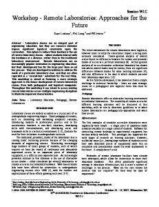
which triggers K4, which triggers K2 back forming the RTH1 reverberating loop. Note that when any coalition (K2, K3 or K4) is triggered the RTH1 loop is ‘turned ON’. The other rhythm is sustained by K6, which triggers K7, which triggers K8, which triggers K6 back, forming the RTH2. When K0 starts the simulator it triggers both K2 and K6, so these two loops are synchronized (see Fig. 1), which means the events K2 and K6, K3 and K7, K4 and K8 occur respectively at the same time. Users can change the network topology by changing in simulator the matrix Topol. For example, the first vector says: Topol = [ 0 2 sw tINev dNT; 0 6 sw tINev dNT; … it means that K0 is connected to K2 with the default synaptic weight sw, the spike delay propagation among these coalitions is held in tINev (ms) and the default neuron type (dNT) is used for K2. The second vector says that K0 is also connected to K6 with the synaptic weight sw, tINev (ms) is the spike delay propagation among their neurons, and the default neuron type dNT is used for neurons of assembly K6. Now, let us analyze the loops RTH1 and RTH2. In order to construct these loops the following vectors are added: 2 3 sw tBD dNT; 3 4 sw tBD dNT; 4 2 sw tBD dNT; 6 7 sw tBD dNT; 7 8 sw tBD dNT; 8 6 sw tBD dNT; it means that K2 is connected to K3 with the default synaptic weight sw, the delay propagation among them is held on tBD (| 40 ms), K3 having the neuron type dNT. The next vectors describe that K3 is connected to K4, and K4 is connected to K2 closing the loop. The vectors on the subsequent line describe that K6 is connected to K7, K7 to K8, and that K8 is connected back to K6. All connections have the same delay propagation (tBD); thus, regular time firing intervals are expected for these coalitions, which can be observed in the raster plot (Fig. 1). In order to construct an OR function, the following vector line is added: 2 10 sw tBD dNT; 7 10 sw tBD dNT; 8 10 sw tBD dNT; These vectors say that the neurons from assembly K2 are connected to the neurons of assembly K10, the next vector says that K7 is also connected to K10, and the last vector says that K8 is connected to K10. All neurons in these three groups are connected with the synaptic weight sw, they have the same delay propagation, and the default neuron type. Thus, the sum of all connections weighted sw is equal Θ; hence, when spikes from K2, K7, or K8 reach the K10’s neurons this assembly is triggered. It means that any of these coalitions can trigger K 10 independently. That is why the frequency of K10 is three times greater than in K2, K7 or K8: each occurrence of these events causes the K10 triggering, so the K10 occurrence is tripled. In terms of logical functions, the raster plot (Fig. 1) shows that K10 can be triggered by K2 OR K7 OR K8.
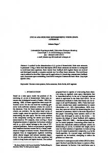
then information become travelling spikes. Thus, the state of such BNA can only be changed during interactions with the member ‘nodes’ (the member assemblies). Moreover, once it is a loop, a BNA would in thesis remain active indefinitely. In this case, it is necessary other coalitions for playing the veto or inhibition role. An assembly can dismantle a BNA or any branch by inhibiting another assembly. In this case, such coalition executes the NOT logical function. Moreover, two assemblies may be necessary (AND) in order to inhibit another assembly, and such conjunction executes the NAND logical function (an AND associated to a NOT function). The same reasoning is true for OR associated to inhibition, which creates the NOR logical function. Fig. 1 shows a raster with the above described functions being executed in a simulation. The Matlab code and a tutorial for this simulation are available at [14], [15].
Fig. 1. Fundamental relations of DAs. This raster plot shows the logical relations performed by digital assemblies, which are polychronous groups with 20 neurons per assembly. Coalitions K2-K3-K4 perform a bistable loop, as well as K6-K7-K8 . K10 performs the OR logical function (K10 ← K2 + K7 + K8), while K12 perform an AND (K12 ← K4 • K8). K14 performs the NOT ������������ function inhibiting K8 , acting as a NAND function (�� ← � � • �� ).
Each neuron is numbered and plotted on the ordinate axis. Assemblies are distinguishable by sequential groups of cells firing together, labeled from K0 to K14. Each assembly has 20 neurons. Two coalitions are reserved by the system: K 0 starts the simulation process and K1 serves as constant ‘1’ input every time K2 fires. Whenever users want input (K1) to be ‘0’ it must specify it in the InputString vector. For example, if InputString = [1 0 0 0 0 1 0 1 0] then K 1 fires at the first K2 event, it does not fire for the next four K2 occurrences, it fires again coincidently at the sixth K2 event, and so on. By doing so it is possible to trigger the system only once (at K0) and then all the other events are activated internally by coalitions, except for the K1 veto, performed by the system whenever users do not want K1 firing with K2 (whenever a bit ‘0’ is found within the string). In this sense, K2 works as a pacemaker for the string inputs. In order to demonstrate the logical functions two groups are used as ‘rhythm’ generators, similar to clock signals in digital computers. One rhythm is sustained by K2, which triggers K3,
�� ← � + � + �� (2) The vector line that constructs an AND logical function is: 4 12 sw/2 tBD dNT; 8 12 sw/2 tBD dNT; These two vectors connect the assembly K4 to K12 and K8 to K12, but each one with only half of the synaptic weight (sw/2). It means that alone neither K4 nor K8 can trigger K12. Note in Fig.1 that K12 occurs only 40 ms (tBD) after the coincident
30
occurrence of K4 and K8. It means that |40 ms after K4 AND K8 fire, their spikes reach K12 making this assembly to fire: �� ← � x �� (3) In order to cause an inhibitory function in simulation the following line vector is added: 1 14 sw/2 tBD dNT; 12 14 sw/2 tBD dNT; 14 8 -sw tBD dNT; These vectors connect K1 and K14, and also K12 and K14 using sw/2. So, K14 is triggered when K1 and K12 coincide (an NAND function) but note that K14 is connected with a negative synaptic weight –sw to K8. It means that when K14 happens it inhibits K8, so K14 is functioning as a NAND function. Once K8 receives the spikes from K7 and from K14 at the same time, they cancel each other and the event K8 does not happen. Concisely, when InputString has a ‘1’ bit in its sequence, the system does not cause K1 veto, so K1 fires. K1 and K12 trigger the NAND K14 that dismantles the loop RTH2. How is it possible to confirm that logical functions were executed before and after dismantling RTH2? Note that after dismantling RTH2, K7 and K8 cannot trigger K10 anymore, but K2 remains firing. As K2 is one input of the OR function, it triggers K10 singly, because K2 is connected with sw to K10. Hence, after K14, the coalition K10 has the same frequency as K2, although phase shifted by tBD milliseconds. After K14, K12 becomes silent because it depends on K 4 and K8 occurring simultaneously; but K8 becomes silent after the dismantling of RTH2. Once K4 contributes only with half of the perturbation (sw/2) and K8 is ‘OFF’, K12 cannot be triggered. Even after RTH2 dismantled RTH1 remains firing. That is because there is no inhibitory event applied to RTH1 members. Note that both RTH1 and RTH2 perform memory loops. They retain one bit of information: the event which caused them, the event they are representing. Once they are reverberating loops, they would remain active indefinitely if not dismantled. In this case, RTH2 was dismantled but RTH1 remains ‘memorizing’ the initial event K0. In this sense, they can be short- or long-term memories. Thus, it causes no surprises that inhibition plays important roles in NAC (and in biological neural networks) for dismantling branches or active loops; otherwise the spiking network would increase the number of active reverberating loops in an ‘epileptic’ manner. These are the fundamental concepts in NAC. These are also fundamental elements that engineers use to create sequential digital machines and computers. Thus, let us analyze how NAC can perform finite state machines. IV.
a set of states and triggering conditions that cause transitions. Automata are often classified by the class of formal languages they can recognize: finite, regular, context-free, contextsensitive languages (see overview in [16]). Further discussion on automata theory is out of the scope of this paper. A. FSA and Biological Systems NAC is concerned with realizing networks biologically plausible; thus, it is important to get support on biological findings when proposing some kind of computation on NAC. Central pattern generators (CPG) are neural kernels capable of generating patterned rhythms and signals for information processing, but CPGs are also pointed out as responsible for generating patterned movements, such as the gaits for legged locomotion in animals [17]. As pointed out by Ijspeert: “there are several interesting properties that make CPG models useful for the control of locomotion in robots as an alternative to methods based on finite-state machines, sine-generators, prerecorded reference trajectories,” [17]. One can design certain types of CPG using FSA, in which each state in the automata generates an output pattern. It can be useful as gait generators in robots, or in sequential output for serial machines. In summary, pattern generation is common in biological systems and it can be implemented by means of FSA, but this is not the focus of this article. FSAs are also investigated as pattern recognizer in other stereotyped biological behaviors, such as language recognition and language production in humans and in animals, for example, the birdsong syntax has been studied having FSA as a fundamental component (review in [16]). B. Implementing FSA Let us joint what was described in previous sections and design a FSM capable of recognizing a pattern. Let us limit the ‘alphabet’ or our machine to characters ‘0’ and ‘1’, and let us arbitrarily choose the “100” as the sequence to be detected.
FINITE AUTOMATON ON NAC
A FSA is a mathematical abstraction, “a computational model of a machine with finite memory, consisting of a finite set of states, a start state, an input alphabet, and a transition function that maps input symbols and current states to some set of next states” [16]. In other words, FSA is an abstract machine that can be only in one of a finite number of states at a time. A specific condition or a triggering event may cause a transition, which changes the machine from one state to another. Thus, a particular FSA, or FSM, is defined in terms of
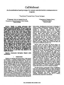
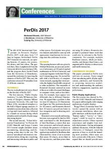
Fig. 2. States Diagram and Equations. States diagram of a FSA capable of detecting “100” as an input pattern. The top equations describe how to trigger new states while the below equations describes how to dismantle current state. For example: once in S0 and the input is ‘1’, S0 dismantles itself (�� ← 1 • � ) and this situation triggers S1 (�� ← 1 • � ).
31
As discussed earlier, assemblies may represent ‘things’; actually, they stand for the event that triggers them. A FSA created on NAC memorizes states into reverberating loops (BNAs). In this sense, “100” may signify a sequence of events with a semantic meaning: “if the animal is hungry ‘1’, and no visible food is observed ‘0’, and no food smell is felt ‘0’, then trigger a pattern generator for foraging”. This is a meaning or application for an automaton like the one described here. The first step for designing a FSA on NAC is to draft a state diagram, as shown in Fig. 2. In this diagram all the possible states are represented by circles, each one labeled with a unique name. In Fig. 2 the S0 state is the initial state, indicated by the init arrow. When the automaton is in S0, if a ‘0’ is applied to the input the FSA has to stay put, but if a ‘1’ is applied to the input the machine must go to state S1. It means that once a ‘1’ comes to the input the first element in the sequence is detected, so the machine goes to S1. Then, once the machine is in S1 and a ‘0’ is applied to the input a transition forces the machine to state S2. In this case, a “10” is detected. When the FSA is in S 2 and another ‘0’ is applied to the input then the machine goes to the final state S3 (the double circled state). When the FSA achieves state S3 it may stop or it may continue indefinitely detecting the same sequence from an input streaming (a string). This is the case here: once in S 3 and a ‘0’ comes from the string, the FSA restarts at S0, but when the input is ‘1’ it means the first state in the sequence “100” has already come, and the cycle is repeated from S1. Starting from S0 or S1 and reaching S3 is the forward flux the machine follows when detecting the “100” sequence. However, all the other possibilities must be predicted when designing the FSA. Hence, when in S0 and a ‘0’ comes the machine must continue in S0. When in S1 and ‘1’ comes it means that the first character in the sequence has already appeared, thus, the machine stays at S 1. When in S2, it means “10” has already appeared, but if a ‘1’ comes the sequence is broken (“101”). However, the first element ‘1’ has already appeared so, from S2 the FSA has to go to S1 when ‘1’ comes. Adaptations were made on the diagram in Fig. 2, which differs a little from Moore and Mealy diagrams (two ordinary methods used for designing sequential machines). Note that each transition has a self-dismantling branch. As said, in NAC a state is represented by a bistable loop; thus, each transition must dismantle the state it is leaving, a simple task that can be performed by an inter-neuron group. Continuing with the methodology, after defining the state diagram, Boolean equations can be obtained for this specific machine. For instance: � ← 0 x � + 0 x �� can be read S0 is triggered whenever the FSA is in state S0 and a ‘0’ comes, OR whenever the FSA is in S3 and a ‘0’ comes. Some algebra reduces the sentence to: � ← 0 x (� + �� ) which means when a ‘0’ comes and the machine is in S 0 OR in S3, execute the transition to S0.
Equations must also be obtained for inhibitory transitions. For instance, when leaving S3 the automata must dismantle the S3 state. Another example: an equation for dismantling S0, in Boolean notation is: � ̅ ← 1 x � this equation can be read as: dismantling S0 (NOT S0) occurs whenever the machine is in S0 and a ‘1’ comes as input. C. FSA Simulation The FSA described above was simulated in Matlab, the code is available at [14], a tutorial is also available at [15], and the results are shown in the Fig. 3. Users can change the input sequence by changing the vector InputString[] in the code. Other parameters can be changed, for example, coalitions can be simulated as synfire chains (firing synchronously [18]) or as polychronous groups (firing time-locked [19], [20]. In addition, the global perturbation (Θ) can be altered in Teta; the default propagation delay in tDB, among others. Please, refer to the tutorial for further details. Thirty nine coalitions were used in order to create the FSA. The coalition K0 was used for starting the simulator. It triggers both the ‘rhythm’ bistable loop (K2-K6) and the starting state loop S0 (K12-K16). Every time K2 fires the system introduces a new character on the FSA. Users can read the input string by looking the K1 coalition. When K1 is firing the input character is ‘1’ otherwise the input is‘0’.
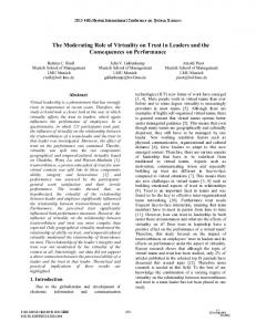
Fig. 3. FSA detecting “100”. Raster plot showing the simulation of a FSA detecting “100” from an input string. At each K2 occurrence one input character is presented to the FSA. If K1 fires the input is ‘1’ otherwise it is ‘0’. The group of coalitions S3 is the final state when “100” is detected.
In order to isolate the FSA from the system influence some interneuron coalitions were added: K8, K9, and K10. Coalitions K7, K11, K15, K18, K25, and K32 were intentionally not used for better visualizing the raster plot. Assemblies K17, K24, K31, and K38 are inhibitory interneuron coalitions that dismantle S0, S1, S2 and S3 respectively. Remember that S0, S1, S2 and S3 are
32
BNAs which need to be inhibited for becoming inactive. Similar to the clock in digital circuits, the rhythm signal is dictated by K2, K3, K4, K5 and K6 (a BNA), a loop that remains active indefinitely creating a pattern that governs the timing for this automaton. State S0 is represented by K12, K13, K14, K15, and K16 (a BNA), while K17 dismantles S0. State S1 is represented by the BNA K19, K20, K21, K22, and K23, associated to K24 that is responsible for dismantling S1. State S2 is represented by K26, K27, K28, K29, and K30, while K31 is responsible for dismantling S2. Completing the description, S3 is represented by the BNA K33, K34, K35, K36, and K37, while K38 dismantles the state S3.
machines can be implemented on NAC, a FSA was designed. Simulations and correlate discussions were presented. Other pattern recognizers by FSA have been simulated using the same methodology and the same code available for download. The findings described above are important because they show a way to implement digital automata on spiking neural networks. FSAs as pattern detection are studied in several biological systems, for instance in birdsongs, in both learning and generating song patterns. FSAs as pattern generators are also used for gait generation and other actuator systems, and they can be used for robots and agent implementation. The creation of FSA on NAC opens new perspectives on SNN designs, as well as new ways to think how brains compute.
D. Results Now it is possible to read the raster plot in Fig. 3. Note the inputs occurring synchronized to K2 and how it may cause a transition in the FSA. For instance, S3 (K33 - K37) fires only after S2 (K26 - K30) is ON (firing) AND K1 is OFF (‘0’ or not firing). This happens only at the moment K2 is firing. It means the final state (S3 firing) is achieved and the sequence “100” was detected. After this, as the next K2 occurs, the machine goes to S1 (K19 - K23 firing) if K1 is ‘1’, otherwise it goes to S0 (K12 - K16 firing) if K1 is ‘0’. A randomized noise was introduced (by changing the noiseFactor) from 0.05 up to 0.15 pA (neuron type=1) and the FSA continues executing the function perfectly. It means that this machine running in NAC is quite robust.
REFERENCE [1] [2]
[3]
[4]
[5] [6] [7]
V.
DISCUSSION
In biological terms, the distribution of synaptic weights in NAC seems to be unrealistic and biased. Actually it is. In organisms, tissues and organs result from genetically biased protein creation. If complex organs can emerge from genes why not to admit that important species-specific neural structures can be created by genes? For some structures, synaptic connections are strongly biased in NAC, so, it is assumed that some topologies has biased ‘hardwired’ synaptic strength and that some assemblies are interconnected by ‘favored’ synaptic weights. Thus, machines discussed in this paper are (meanwhile) a priori deterministic.
[8] [9] [10] [11]
[12] [13]
Learning in NAC is understood as neurons changing their correlations with some strongly biased neighbor structure. In other words, NAC machines may have strong predefined networks executing logical functions, bistable loops, and FSAs. Our intuition is that neighbor neural circuitry may become a kind of ‘adaptive finite state automata’ as the network passes through experiences. The learning issue is not shown here, and learning on NAC is under development. VI.
[14] [15] [16]
[17]
CONCLUSIONS
[18]
An overview of the main concepts of NAC was presented. It was shown that spiking neural coalitions interact performing AND, OR, NOT, NOR, and NAND logical functions. In their interactions assemblies also create reverberating loops capable of memorizing one bit. In order to demonstrate that serial
[19] [20]
33
J. Ranhel, “Neural assembly computing,” Neural Networks and Learning Systems, IEEE Trans. on, vol. 23, no. 6, pp. 916–927, 2012. D. O. Hebb, The Organization of Behavior: A Neuropsychological Theory. Mahwah, NJ: Lawrence Erlbaum Associated, Inc, 2002, originally published: New York: Wiley, 1949. J. Wickens and R. Miller, “A formalisation of the neural assembly concept 1.constraints on neural assembly size,” Biological Cybernetics, vol. 77, no. 5, pp. 351–358, 1997. A. K. Engel, P. Fries, and W. Singer, “Dynamic predictions: oscillations and synchrony in top-down processing,” Nature Reviews Neuroscience, vol. 2, no. 10, pp. 704–716, 2001. G. Buzsáki, “Neural syntax: Cell assemblies, synapsembles, and readers,” Neuron, vol. 68, no. 3, pp. 362–385, 2010. G. Buzsáki and A. Draguhn, “Neuronal oscillations in cortical networks,” Science, vol. 304, no. 5679, pp. 1926–1929, 2004. V. Lopes-dos Santos, S. Conde-Ocazionez, M. A. L. Nicolelis, S. T. Ribeiro, and A. B. L. Tort, “Neuronal assembly detection and cell membership specification by principal component analysis,” PLoS ONE, vol. 6, no. 6, p. e20996, 2011. E. M. Izhikevich, “Simple model of spiking neurons,” IEEE Transactions on Neural Networks, vol. 14, no. 6, pp. 1569–1572, 2003. ——, “Which model to use for cortical spiking neurons?” IEEE Transactions on Neural Networks, vol. 15, no. 5, pp. 1063–1070, 2004. E. Kandel, J. Schwartz, and T. Jessel, Principles of Neural Science. 4th ed. New York, NY: McGrall-Hill Health Prof. Division, 2000. D. Purves, G. J. Augustine, D. Fitzpatrick, W. C. Hall, A.-S. Lamantia, J. O. McNamara, and M. S. Williams, NEUROSCIENCE. 3rd. ed. Sunderland, Massachusetts U.S.A.: Sinauer Associates, Inc., 2004. E. Izhikevich, J. Gally, and G. Edelman, “Spike-timing dynamics of neuronal groups,” Cerebral Cortex, vol. 14, no. 8, pp. 933–944, 2004. J. Ranhel, C. Lima, J. Monteiro, J. Kogler Jr., and M. Netto, “Bistable memory and binary counters in spiking neural network,” in FOCI 2011 Proceedings, I. Press, Ed., vol. 1. IEEE Press, 2011, pp. 66–73. J. Ranhel, “Matlab file for simulating NAC basics,” 2012. [Online]:. http://www.neuralassembly.org/download/NAC_FSM_basics.m ——, “Tutorial for FSA on NAC simulator,” 2012. [Online]: http://www.neuralassembly.org/download/NAC_FSM_Tutorial.pdf R. C. Berwick, K. Okanoya, G. J. L. Beckers, and J. J. Bolhuis, “Songs to syntax: the linguistics of birdsong,” Trends in cognitive sciences, vol. 15, no. 3, pp. 113–121, 2011. A. J. Ijspeert, “Central pattern generators for locomotion control in animals and robots: A review,” Neural Networks, vol. 21, no. 4, pp. 642–653, 2008. M. Abeles, “Synfire chains,” Scholarpedia, vol. 4, no. 7, p. 1441, 2009. [Online]: http://www.scholarpedia.org/article/Synfire_chains E. Bienenstock, “A model of neocortex,” Network: Computation in Neural Systems, vol. 6, no. 1, pp. 179–224, 1995. E. M. Izhikevich, “Polychronization: computation with spikes,” Neural Computation, vol. 18, no. 2, pp. 245–282, 2006.