Indian Journal of Science and Technology, Vol 9(26), DOI: 10.17485/ijst/2016/v9i26/89824, July 2016
ISSN (Print) : 0974-6846 ISSN (Online) : 0974-5645
Neural Network Enabled WSN Management for Energy Eicient Routing Mechanism Nilayam Kumar Kamila1*, Sunil Dhal2 and Bhagirathi Nayak2 1
2
Capital One, Wilmington, Delaware, USA;
[email protected] Sri Sri University, Odisha, India;
[email protected],
[email protected]
Abstract Background/Objectives: To design a model for Wireless Sensor Network which manage the routing mechanism efficiently and reduce the power consumption during packet routing. Methods: Neural Network Approach e.g. Self-Organized Map and K-Means Algorithms used for cluster selection and election to improve the energy efficiency. Findings: Neural Networks algorithms in combination of cluster head load sharing and self-silence model provides a better performance than the existing Wireless Sensor Network routing protocols. Improvements/Applications: This design approach can be further enhanced through Fuzzy based neural network model.
Keywords: Network, Neural WSN Routing, Reverse Transmission, Sensor Network, Sensor Cluster,
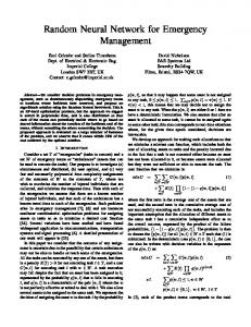
1. Introduction Wireless Sensor Network is based on a set of sensor nodes deployed on areas where there is very limited or no access for human monitoring. he sensor nodes constitute of four basic units such as sensing unit, transmission and receiving unit, processing unit and power unit1. he environmental change, or target point behavior change is sensed by the sensing unit and the data captured through the sensing unit is forwarded to other sensors through transmission unit. he receiving unit will receive the data from other sensor nodes. he processing unit will process the data and also may involve processing any intermediate computations. he power unit consists of battery which is the main source of power in sensor device. he deployment of nodes in the speciic area is random and it becomes very much diicult to repair or maintain the sensor nodes ater deployment. Hence it is absolute necessary to conserve the battery energy as much as possible with minimum usage. As shown in Figure 1, the sensor nodes sense the data from the target object and send towards the base station. Base Station is a gateway to outside networks. It has continuous power supply, and has no constrains of power *Author for correspondence
source and have the high processing and storage units. So basically, base station is the unit where complex computational task2 could be accomplished and also large unit of data sets could be housed which may require for current and future computations. Once the sensors’ gathered data received by base station, base station will again integrate and process it according to the desired format and send to other network for users’ usage or further processing. In this paper, next section will review few related protocols which approached for neural network based and non-neural based. Section 3 covers up the proposed Neural Network Enabled WSN Management (NNEWM, pronounced as ‘anneum’) approach with the process lows, and respective algorithms. Mathematical Analysis and Simulation Analysis comparison of our proposed NNEWM approach with related protocols is discussed in subsequent section followed by conclusion and future scope of the work.
2. Related Protocols Review here are multiple number of protocols have been emerged in the ield of wireless sensor network protocol3-5. Before
Neural Network Enabled WSN Management for Energy Eicient Routing Mechanism
Base Station
Ï Ô p Ô , if n ŒG Ê Ô 1ˆ T (n) = Ì1 - p Á rmod ˜ p¯ Ë Ô 0, otherwise Ô Ô ÔÓ
WSN Regions
Internet
(3)
Other nodes ater receiving the data packets and strength of the signal, chooses which cluster head they need to choose and start transmitting the data to that cluster head in steady state.
Sensor Target User
Figure 1.
2.2 Low Energy Adaptive Connectionist Clustering (LEA2C)
WSN regions and base station setups.
we move to discuss few of the related protocols, let’s discuss the energy equations of the WSN Radio model. he wireless sensor nodes dissipated the battery energy for transmitting and receiving the data. he amount of energy dissipated for transmitting and receiving is given in the below sub-section. he Radio Model Etr ( pd , d ) =Œte pd + Œta pd d 2
(1)
Er ( pd ) =Œr pd
(2)
Where ete and er means the power dissipated to run the transmitter or receiver circuitry and eta is the power for the transmit ampliier.
2.1 Low Energy Adaptive Clustering Hierarchy (LEACH) LEACH6 protocol has come with revolutionary change in cluster based routing protocols. he whole network is divided into separate clusters and each cluster has a cluster head. he nodes of the cluster send the data packets to cluster head and cluster had in turns process the message and send to base station ater data fusion. he main attempt to conserve energy is to randomly select the cluster head. he whole network life time divided into multiple network rounds and each round, there are two state of the network i.e. network setup state and network steady state. Each node chooses a random number between 0 and 1. And if the number is less than T(n) as shown below, then the node is declared as cluster head and send that data packets to other nodes.
2
Vol 9 (26) | July 2016 | www.indjst.org
LEA2C7 is based on LEACHC protocol and is Self Organized Map based protocol. LEACHC protocol uses the same steady state as deined in LEACH protocol, but it sends the current position and energy level to base station. he base station now determines the cluster head and sends the respective information to the clusters8-10 nodes. In LEA2C, SOM followed with K-Means. Ater the clusters being formed the cluster head is selected with one of the three criteria i.e. max energy nodes, nearest node to base station, and nearest node to gravity center. he transmission state continues till the irst node drops from the network. Ater the node drops of from the network, the re-clustering11,12 happens with network setup phase and Base station to continue its SOM and K-Means algorithm to re conigure the network.
2.3 Energy Based Clustering Self Organizing Map (EBC-S) EBC-S1 is a neural network based routing protocol and is very recent13,14 work accomplished in this ield. Here the network setup15-17 and transmission phase followed with close proximity to LEA2C based protocol. EBC-S introduced the Residual Energy parameter as an additional parameter to the Self Organizing Map algorithm for cluster creations. his gives an excellent improvement over the existing LEACH and LEA2C protocols. his protocol ensures 11-27% of improvement over the LEA2C protocol and 90-95% network coverage.
3. Proposed Approach In this model, we visualize the scope of the system into two broad categories, Network Setup scope and Network
Indian Journal of Science and Technology
Nilayam Kumar Kamila, Sunil Dhal and Bhagirathi Nayak
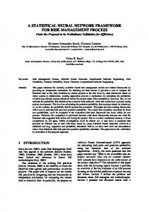
Transmission scope as shown in Figure 2. In Network Setup scope, we tried to resolve the issue of cluster head setup through election process among individual nodes through the Neural Network model and then passed on the same information to the individual sensor nodes about their clustering group with the cluster head information. In Network Transmission scope, the individual nodes send their gathered data to the cluster head and cluster head in turns takes the responsibility to forward the data towards the base station. Also we considered the approach of two cluster head instead of a single cluster head to backup the primary cluster head. he advantages of making a two cluster head instead of a single cluster head is to avoid the failure or energy dry out of primary cluster head due to full loads onto the single cluster head. he load sharing is a best approach in extending the life time of the network. he second major approach is taken as Inactive Silence model where the cluster nodes, which are reaching to a irst threshold energy (Ψth1), (before the second threshold energy (Ψth2) ater which node declared as a dead node), will become self inactive, in order to extend the network life time and to conserve some amount of energy for successive iteration network participation. his is an ideal self-conscious management where instead of all nodes become active and dried out at approximately same time, it would be good, if some of the nodes become silent and reserved for next iteration participation. We could take the approach of making this silence principle imposed at the start of network communication, but due to the information loss risk, we optimized to impose the self silence ater the irst threshold energy level. he other approach is to avoid reverse transmission10 between primary cluster head to secondary cluster head communication during the inal data submission to
3.1 NNEWM Model he NNEWM Model is based on three basic unique model approaches. hese unique models pay a distinct role in various layers of the WSN management, refer Figure 3. hese models described briely in below.
3.1.1 Neural Network Clustering and Dual Cluster Head Selection In this, the two cluster head will be selected through the two phase algorithm proposed in EBCS. he base station will have all the below information to create the cluster in irst step and then electing the cluster head. he following information is used to accomplish the cluster creations and cluster head selection. • he x and y coordinate for each deployed sensor nodes through GPS based system at base station. • Residual Energy of each node, which assumed that at the irst setup phase all nodes have equal residual energy and later the energy state of individual node to send to base station. he energy could also be calculated at base station depending on number of rounds of network communication. As at the initial setup phase, all the nodes have same residual energy level, we assumed that the dual cluster heads should be as close as possible so as to make the coordination between two nodes is minimum. But the advantage will be the load sharing in order to achieve the maximum energy conservation. We’ll discuss about the Neural Network Self Organizing Map and K-Means working mechanism in next section.
3.1.2 Cluster Management by Two Cluster Head
Network Transmission Scope: Dual Heads, Reverse Transmission & Self-Silence
Base Station
Cluster
base station in each round. his also saves a signiicant amount of energy during network transmission phase.
Network Setup Scope: Neural Network SOM & K-Means Process
Dual Cluster Head manages the network with network management load sharing. All the nodes are intimated by the base station regarding their primary and secondary Neural Network K-SOM for clustering Two Cluster Head Management
Sensor
Self Management - Self Silence
Target
Cluster Head
NNEWM – Proposed Model
Figure 2. scope.
NNEWM neural network based model approach
Vol 9 (26) | July 2016 | www.indjst.org
Figure 3.
NNEWM proposed model basic unit concepts.
Indian Journal of Science and Technology
3
Neural Network Enabled WSN Management for Energy Eicient Routing Mechanism
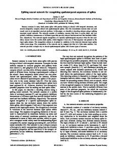
cluster heads. he nodes which are close to primary would communicate to primary and the nodes which are close to secondary cluster head would communicate to secondary cluster head, refer Figure 4. If any one of the cluster head fails, then the other cluster head becomes the sole cluster head and all the nodes will send their sensed data to this cluster head. Advantages of dual cluster head over two clusters’ heads • If one cluster head dies, then the other cluster head become the primary cluster head and reduce the risk of network re-coniguration. • Avoid too many small clusters with one head. • Load sharing between two cluster heads, which will conserve some energy at cluster head level and hence the network life time will be extended, otherwise frequent clusters selection and followed by cluster head selection. • Opens up the fair chance of RTRA10 routing, avoids reverse transmission between nodes which is (are) in the path of cluster heads towards base station, but in the same cluster.
3.1.3 Self-Management – Self Silence In the self silence mechanism, each cluster nodes maintains two threshold level of energy where the irst threshold is to inactivate the node and second threshold is to make the node declared as dead node. So during each transmission of sensed information to the cluster head, the energy of the respective node dissipates and hence the residual energy reduced. When the residual energy reached to the irst threshold level energy, then the node become silent and do not participate in the network communication till a certain period of time. he below are the advantages of this self silence mechanism.
• Reserves the energy of individual nodes to participate in next network iteration, extends the network life time. • Reduce the network noise (packet-collisions) and hence saves the overall cluster energy. • Reduce the chance of redundant message forward and hence reducing the energy consumption at message integration task at cluster head level.
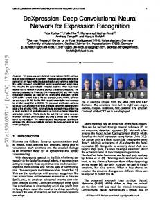
3.2 NNEWM Process Flow Let’s discuss about our proposed neural network model process low. As we discussed in our earlier section, the process low is modeled on the same three basic sub-models. he detail process low steps are shown in Figure 5. At initial network setup, the base station has all the nodes location information as well as the residual energy information (as this is the initial residual energy which we assumed as equal for all nodes). Base station with this information start the initialization of network (refer Network Initialization section of this paper), and with the help of neural network based SOM (Self-Organized Mapping) algorithm, it will organize optimized clusters. he cluster is then taken into consideration and ith the help of K-Means, it will ind out the cluster heads (primary and secondary). his primary and secondary cluster head information is then sent to each node, and based on the primary and secondary cluster heads, the nodes are virtually self-organized to clusters and starts network message communication. Neural Network for clustering Is
Yes
applyNNEWMKSOM : Base Station to apply neural network K-SOM Algorithm to generate clusters and heads(primary & secondary) information
No Sensor nodes to send their residual energy information to base station
Base station to send the respective cluster head (primary and secondary) information to each node.
Details
Base Station
Cluster
Nodes send messages to Cluster Head(primary or secondary)
Each Nod to send message to nearest cluster head (primary or secondary) Is
No
Is nearest chNot Available ?
Dual Cluster Heads
Yes Sleep & Silence Send the message to alternate cluster head(i.e. instead of primary send to secondary and vice versa)
Figure 4.
4
Sensor
Secondary Cluster Head
Cluster Head
Target
Cluster management with two cluster head.
Vol 9 (26) | July 2016 | www.indjst.org
Yes
Is
Dual Cluster Head Management
Figure 5.
No Self Silence
NNEWM process steps and low.
Indian Journal of Science and Technology
Nilayam Kumar Kamila, Sunil Dhal and Bhagirathi Nayak
Now both the cluster head shares the loads and stabilize the network for an extended period of time. Each node starts sending the message to the nearest cluster head. Sometimes due to channel unavailability and busy services of cluster head, the nearest cluster head found to be unavailable. At this time, the nodes try to send the message to the next cluster head means, if the node has been sending to primary cluster head and at one speciic time it found that the primary cluster head is unavailable, then it will start sending the data to secondary cluster head, and vice versa. In this way the node to cluster head communication continues. During the message transmission process, the network nodes may reach to their irst threshold energy level. Basically in this model we proposed to take 2 levels of threshold energy. First threshold is silence threshold and second one is dead threshold level. Once node reaches a silence threshold, it become silence for a speciic period time, called as silence time. Once it passes the silence time, the node again will participate in the network communication till it attains 2nd threshold level and declared as dead. Dead nodes are never able to participate in the network communication.
3.2.1 Network Setup Phase he proposed algorithm is more or like LEA2C or EBC-S. he assumption is the base Station to make the clustering and cluster heads. he network transmission is accomplished with set of rounds. Each round consists of network setup phase followed with network transmission. We propose, instead of one cluster head for each cluster, two cluster head will be selected for load sharing. he basic assumptions are as follows. • he Base Station has uninterrupted power supply and have the high no constraint on processing and memory units. • he GPS System is in place to determine the position of each node, and BS is also capable to calculate the energy level ater each round. • he nodes (normal and cluster heads) will only participate according to the role & Base station has the coverage for the whole network. • Base station has the knowledge of whole network, so out of two cluster head one cluster head to communicate to other cluster head ater data fusion and one of the cluster head is in the path of other cluster head, then it will avoid reverse transmission.
Vol 9 (26) | July 2016 | www.indjst.org
• Base Station to evaluate the optimized number of rounds, and time intervals are to be set for each node to transmit the data to cluster head. his process continues to that many optimized rounds before the next setup round. • Base station calculates the energy dissipation of each node before the next network setup phase with the energy models and number of deined optimized rounds. However, our protocol runs in two modes i.e. auto-calculate and send-calculate. In auto-calculate, base station will calculate energy levels from all the nodes in the network. For send-calculate, the nodes are responsible to send the energy information to base station. he send-calculate mode has much overheads and have less performance than auto-send mode. he work steps are as follows • he base station will run the neural network SOM algorithm with the inputs of node’s location and residual energy levels. • Ater SOM, it again run the K-Means algorithm to decide the cluster head • Now Base Station will send the cluster head id (primary and secondary) and for each node. • Now for each cluster, if the node id matches (associated with head type e.g. primary or secondary), then it is a primary cluster head or a secondary cluster head. If it does not match, then it’s a normal node. • All cluster head also updated with TDMA map, so that the cluster head (either primary or secondary) will send the data towards base station in the respective time schedule. In order to proceed for the SOM algorithm, the base station to choose optimized m-number of nodes with highest energy. And then choose the closest neighbor of this highest energy node. We have chosen the closest node which is in the path of base station and the previously chosen node in order to avoid reverse transmission (RTRA10) at the inal data submission to base station. he Weight matrix is as follows, ˘ È x1 ( x min + x max ) x2 ( x min + x max ) xm ( x min + x max ) . ˙ Í ˙ w=Í y1 ( y min + y max ) y2 ( ymin + y max ) ym ( y min + y max ) . ˙ Í Í1 - È Ψ + Ψ’ Ψ + Ψ’ ˘ 1 - È Ψ + Ψ’ Ψ + Ψ’ ˘ . 1 - È Ψ + Ψ’ Ψ + Ψ’ ˘ ˙ max max 1 1 2 2 max max m m max max ÍÎ Î ˚ Î ˚ Î ˚ ˙˚
(
)
)
(
(
)
In proposed model, we have taken the learning with the minimum Euclidean distance. he map prototypes weighted by a neighborhood function. So the Error function is n
E=
m
ÂÂh
ji
||w j − xi ||2
i =1 j =1
Indian Journal of Science and Technology
5
Neural Network Enabled WSN Management for Energy Eicient Routing Mechanism 2ˆ Ê w j - xi ˜ , and the lattice width is Where h = exp Á ji Á 2s 2 (t ) ˜ ¯ Ë t s (t ) = s (0)exp(− ) l he learning rate is a(t ) = a(0)(1 − t l) , where t the number of iteration is, l is the maximum number of iteration or the training length. So the Weight matrix update ater each iteration is as follows,
w j (t + 1) = w j (t ) + a(t )h ji (t )( xi (t ) − w j (t )) he SOM ater multiple iterations is now able to cluster the nodes and now each of such clusters will be fed to the K-means algorithm to trace the cluster heads. he K-Means algorithm focus to minimize the following expression Ek =
1 K
K
ÂÂ
x − ck
2
k =1 x ∈Ck
Where K the number of clusters is, Ck is the kth cluster and ck is the centroid of the kth cluster. Algorithm 1.0: NNEWMSetupProcess() Inititilize: Number of Highest Energy Nodes Gather location Information from GPS and Energy Information from WSN device Speciication Build the Weight Matrix w E = EInit While E > Eth do evaluate s(t) and hji evaluate E update Wight Matrix w end-while evaluate DB Index while Ek > Emin do for each Cluster for each node in Cluster Ck calculate Dk =
Â
x − Ck
x ∈Qk
end for C
calculate Ek =
ÂD
k
k =1
end for Ek = (1/C)Ek end-while
To obtain the optimized number of clusters, we use the DB (Davies-Bouldin) index. DB index is the ratio between intra-clusters scattering to inter-cluster distances and is expressed as I db =
1 k
k
 max j=i k =1
(di + d j ) dij
Where di is the average distance between each point of ith cluster and the centroid of ith cluster. Similarly, dj is the average distance between each point of jth cluster and the centroid of jth cluster and dij is the Euclidian distance between the centroid of ith cluster and jth cluster. We have shown below the overview of the algorithm where the algorithm initializes with the number of nodes in SOM map with their locations and the two closest nodes with maximum energy. As mentioned above the algorithm will initialize the weight matrix and then continue to build m-number of cluster till the Error function value E attains the less value than Eth. As a next part it will evaluate the optimum number of cluster based on the DB Index value as shown above. And now the base station has the optimum number of clusters and their cluster nodes information (location and corresponding residual energy value). With this information the Algorithm now evaluate the cluster head. We have taken the criteria to choose maximum energy value for the cluster head, and the nearest neighbor with the next highest energy valued node will be considered as the secondary cluster head. Ater complete execution of this algorithm, the base station has the following set of information. • Number of optimized clusters in the whole set of network. • Each clusters two cluster head information (location and residual energy). • All member nodes information (location and residual energy) and which cluster they belong to.
2
3.2.2 Network Transmission Phase So with the above information, base station computes the clusters and their cluster heads (primary and secondary) and send the information to the nodes to start the transmission phase. Algorithm 2.0: NNEWMTransmissionProcess() Initialization: Initialize ts, Ψth1, Ψth2, ΨC , Ψcp th
6
Vol 9 (26) | July 2016 | www.indjst.org
Indian Journal of Science and Technology
or (ψ c > ψ cth
Nilayam Kumar Kamila, Sunil Dhal and Bhagirathi Nayak
while (Ψc > ΨC or Ψc > ΨC ) th th for each node do if (ΨRE > Ψth2) then break; //Node is dead, exit process for other node end-if if (ΨRE > Ψth1 && te < ts) then break; //Node is silent, may participate in next time end-if send data to cluster head (CorC' ) Calculate Sending Energy as ψn =∈te pd + ∈ta pd d 2 Calculate Receiving Energy at cluster Head as ψcr =∈r pd Or ψc ¢r =∈r pd Add Processing energy (Ψcp) at cluster head ψ c = ψ cr + ψ cp Or ψ c ¢ = ψ c ¢r + ψ cp if (ψ c < ψ cth & &ψ c ¢ > ψ cth )or (ψ c > ψ cth & &ψ c ¢ < ψ cth ) & &ψ c ¢ < ψ cth ) then if (ψ c < ψ cth & &ψ c ¢ > ψ cth ) then make C ′ as Cluster Head else
make C as Cluster Head end-if end-if end-for end-while if (ψ c < ψ c & &ψ c ¢ < ψ c ) then th th NNEWMSetupProcess(); end-if During the K-Means algorithm execution, we have taken the maximum energy as cluster head as part of the scope of this paper. he other two approaches e.g. nearest node to base station and the node in Centroid of Gravity are part of our future scope. So as the cluster members are now not involved in the cluster head election process, so there is an excellent improvement in energy conservation. Now the base station will send the respective primary and secondary cluster head id to all the cluster nodes. If the id matches with the cluster node, then the cluster will act as a cluster head primary or secondary. he prime responsibility of this type of node is to aggregate the data and send to the base station. If id does not match with the self-id, then it is a normal node and the node collect the sensed information and sends to the node whose id it receives from the base station during current round of the network transmission. As the proposed protocol already have a primary and secondary cluster head, so proposed protocol will continue to execute multiple round (irst lip of role
Vol 9 (26) | July 2016 | www.indjst.org
of cluster head when primary or secondary below 20% of energy, and still continues when the other one too goes below 20% of energy) of this phase before go for the next network setup phase. In lip of role, one cluster head will convey to other cluster head and goes silent (no receive and no send). he other cluster head will continue till it goes below 20 % (ΨC ) of energy. All other nodes will become th silent for a speciic silent time (ts), when they attend 35% of energy (Ψth1) and will only listen to base station broad cast message for new re-cluster message during this time. Ater they pass the silent time ts, they can again participate in the current round network transmission. he energy dissipation is calculated as per the equation 1 and 2.
4. Mathematical Analysis he mathematical symbols used in this section are described below. : Distance between ith and jth node : Number of nodes in the network. : Sensor radio transmitter energy and transmitter ampliier power : Sensor radio receiver energy : data packet size for election packet.
dij n ∈te, ∈ta ∈r pel ψ ttl , ψ tlr , ψ tl r ψ tnn , ψ nn , ψ nn
: transmitting, receiving and combined energy for traditional (non-neural) based protocol : transmitting, receiving and combined energy for proposed neural network based protocol
he energy required to execute the election process without neural network approach is shown below. For ith node, the energy required to transmit the election packet pel is given by È n-1 ˘ ψ tt 1 = (n −1) ∈te pel + ∈ta pel Í dij2 ˙ ÍÎ j -1 ˙˚
Â
Energy required for each node to receive election process as follows ψ tr1 = (n −1) ∈r pel So for each node, the total energy dissipated in participating election process is È n-1 ˘ ψ tl = (n −1)(∈te + ∈r ) pel + ∈ta pel Í dij2 ˙ ÍÎ j -1 ˙˚
Â
Indian Journal of Science and Technology
7
Neural Network Enabled WSN Management for Energy Eicient Routing Mechanism
So total energy dissipated by all n number of nodes in participating election process is È n,n-1 ˘ ψ tl = n(n −1)(∈te + ∈r ) pel + ∈ta pel Í dij2 ˙ ÍÎi =1, j -1 ˙˚
Â
For NNEWM, the energy information to send to base location is for multi-hop communication to base station. È n-1 ˘ ψ tnn = n ∈te pel + ∈ta pel Í d 2jb ˙ ÍÎ j -1 ˙˚
Â
ψ tnn tends to 0 for single hop and multi-hop communication in auto-calculate mode of operation. Westill consider this factor in order to adapt our protocol to adverse conditions where if the mode of operation (send-calculate) requires to send the energy value to base station instead of base station calculates the residual energy based on the energy transmitting and receiving equations. And the energy dissipated in receiving the next iteration cluster heads (primary and secondary) is r ψ nn = n ∈r pel
So total energy dissipated for sending the residual energy information and receiving the cluster heads information is r ψ nn = ψ tnn + ψ nn
È n-1 ˘ ψ nn = n ∈te pel + ∈ta pel Í d 2jb ˙ + n ∈r pel ÍÎ j -1 ˙˚
Â
Now let’s evaluate the expression of the energy dissipation diference dΨ i.e.
d ψ = ψ tl − ψ nn È È n,n-1 ˘ ˘ d ψ = Ín(n −1)(∈te + ∈r ) pel + ∈ta pel Í dij2 ˙ ˙ Í ÍÎi =1, j -1 ˙˚ ˙ Î ˚ 1 n È ˘ ˘ È - Ín ∈te pel + ∈ta pel Í d 2jb ˙ + n ∈r pel ˙ Í ˙ ÍÎ j -1 ˙˚ Î ˚
Â
Â
= n(n − 2)(∈te + ∈r ) pel + ∈ta pel d d Where n -1 ˘ È n,n-1 dd = Í dij2 − d 2jb ˙ ˙˚ ÍÎi =1, j =1 j =1
Â
8
Vol 9 (26) | July 2016 | www.indjst.org
Â
As we assume the base station is not very far from the wireless range of the sensor nodes, otherwise the base station node could not be reachable from the sensor nodes. Hence dd > 0 So for n > 2, i.e. if the cluster has more than 2 number of sensor nodes, then the inequality dΨ > 0 holds true i.e. we mathematically shown that the energy dissipation in our proposed neural network model is less, which conserves an amount of energy dΨ in each iteration. he dΨ is even more if the mode of operation switched so as to make the base station to calculate the residual energy during network setup state.
5. Simulation Studies We have taken the following parameters for our simulation studies. Our scope of simulation is made for single hop communication and the nodes’ residual energy value is calculated by base station for executing the K-Means algorithm to decide the two cluster heads. We found that for 200 nodes simulations in 100 × 100 Square unit area, our proposed NNEWM model have better performance over the LEACH and LEA2C protocols at all the rounds as shown in Figure 6. EBCS is having better performance in initial network rounds as shown in Figure 7. his is due to the NNEWM has two cluster head and the receiving of bigger sized packets than EBCS reduces the overall residual energy. Later the successive rounds, NNEWM protocol has shown a better performance over all protocols. Also we could clearly see that Table 1.
Simulation Parameter and values
Sl.
Parameter Name
Parameter Value
1
Initial Residual Energy
1J
2
Node’s receiver energy ∈r
50nJ/bit
3
Node’s transmitter energy ∈te
100pJ/bit/m2
4
Node’s ampliier energy ∈ta
100pJ/bit
5
Base Station location
Random,Random
6
Size of election packet pel
1024
7
Wireless Coverage
7.5m
8
Area with Nodes(Scene -1)
100 × 100 with 200 Nodes
Area with Nodes(Scene – 2)
150 × 150 with 400 Nodes
Indian Journal of Science and Technology
Nilayam Kumar Kamila, Sunil Dhal and Bhagirathi Nayak
Figure 6. NNEWM vs. LEA2C Vs LEACH over 200 Nodes in 100 × 100 square unit area.
Figure 7. NNEWM Vs LEA2C Vs EBCS over 200 Nodes in 100 × 100 square unit area.
when the Self-silence attained, there is no much residual energy loss, and this extends the network life time signiicantly. Similarly, with 400 nodes over 150 × 150 square units is simulated, and traced the similar behavior for the proposed model over the other related model, refer Figure 8 and Figure 9. We could see the load sharing with two cluster heads, avoiding reverse transmissions between two cluster heads and the nodes’ self-silence to conserve energy for future rounds of network communication, really works well and hence with the help of neural network SOM and K-Means gives a better performance over other neural based network model.
Vol 9 (26) | July 2016 | www.indjst.org
Figure 8. NNEWM vs. LEA2C vs. LEACH over 400 nodes in 150 × 150 square unit area.
Figure 9. NNEWM vs. LEA2C vs. EBCS over 400 nodes in 150 × 150 square unit area.
Our proposed neural network based with two cluster heads and integrated with reverse transmission approach, and with self silence approach have approximate 7.23%8.71% extra energy conservation over the EBC-S model and17.39-19.81% over LEA2C model and 33.81-35.43% over LEACH based model.
6. Conclusion here have been multiple research attempts are made for Neural Network model based approach to conserve energy, and neural network model conserves the energy as
Indian Journal of Science and Technology
9
Neural Network Enabled WSN Management for Energy Eicient Routing Mechanism
compared to traditional models. We presented an integrated model where several approaches towards the energy conservation such as avoidance of reverse transmission, load sharing through two cluster heads, and self-silence. his integrated model (Neural network approach in integration with load sharing and self-silence) has better energy conservation as compared to the related protocols and this is shown with our mathematical analysis and simulation studies. We still continue to implement the fuzzy based neural model for cluster head selection in multi-hop communication as part of future scope of this paper.
7. References 1. Enami N. A new neural network based energy eicient clustering protocol for wireless sensor networks. IEEE Proceedings of 5th International Conference on Computer Sciences and Convergence Information Technology (ICCIT); Seoul, South Korea. 2010 30 Nov–2 Dec. p. 40-5. 2. Saranya V, Matheswari N, Punidha R, Soundarya M. Tracking dynamic target in wireless sensor networks. Indian Journal of Science and Technology. 2016 Jan; 9(1). Doi no:10.17485/ijst/2016/v9i1/85787 3. hiriveni GV, Ramakrishnan M. Distributed clustering based energy eicient routing algorithm for heterogeneous wireless sensor networks. Indian Journal of Science and Technology. 2016 Jan; 9(3). Doi no:10.17485/ijst/2016/ v9i3/80493 4. Kamila NK, Dhal S, Samantaray AK. A survey of neural network energy eiciency management in wireless sensor networks. IJAER. 2015; 10(21):42023-36. 5. Kamila N, Dhal S, Overview of WSN infrastructure models, design and management. IJRITCC. 2016 Mar; 4(3):9–13. 6. Heinzelman WR, Balakrishnan H. Energy-eicient communication protocol for wireless micro sensor networks. Proceedings of 33rd Hawaii International Conference on IEEE System Sciences (HICSS’00); 2000 Jan. p. 4–7. 7. Dehni L, Kief F, Bennani Y. Power Control and clustering in wireless sensor networks. IFIP International Federation for Information Processing. 2005; 197:31-40. 8. Enami N, Askari RN, Haghighat A. A survey on application of neural networks in energy conservation of wireless sensor
10
Vol 9 (26) | July 2016 | www.indjst.org
9.
10.
11.
12.
13.
14.
15.
16.
17.
18.
19.
networks. WiMo Proceedings on Recent Trends in Wireless and Mobile Networks; Ankara, Turkey. 2010. p. 283–94. Raval J, Jagyasi B. Distributed detection in neural network based multihop wireless sensor network. IEEE Sensors Applications Symposium (SAS); Queenstown, New Zealand. 2014. p. 65–8. Kamila Nilayam K, Patra PK, Pradhan PK, Pattanaik PK. A reverse transmission approach for multi-hop routing in wireless sensor network. International Journal of Reviews in Computing. 2010 Oct; 4:1–7. Xiaodong Y, Xiaoli L, Youbing Z, Wenwei Z, Shuaijie R, Guoqing W. An application-speciic WSN routing protocol for EV charging piles management system. IEEE Control Conference (CCC); Hangzhou, China. 2015. p. 7651-8. Vesanto J, Alhoniemi E. Clustering of self organizing map. IEEE Transactions on Neural Networks. 2000; 11(3):586600. Lakshmi Manoja Ch, Aruna Kumari D. Geographical location based hierarchical routing strategy for WSN using movable routers. Indian Journal of Science and Technology. 2016 May; 9(17).Doi no:10.17485/ijst/2016/v9i17/93094 John Livingston J, Umamakeswari A. Internet of hings application using IP-enabled sensor node and web server. Indian Journal of Science and Technology. 2015 May; 8(S9). Doi no:10.17485/ijst/2015/v8iS9/65577 Kashani MAA, Ziafat H. A method for reduction of energy consumption in Wireless Sensor Network with using neural networks. Computer Sciences and Convergence Information Technology (ICCIT); 2011. p. 476–81. Al-karaki JN, Kamal AE. Routing techniques in wireless sensor networks: A survey. IEEE Wireless Communication. 2004:6-28. Heinzelman WB. An application-speciic protocol architecture for wireless networks. IEEE Transactionson Wireless Communications. 2002 Oct; 1(4):660-70. Shamili S, Manivannan D. Sensor node failure detection using multiway tree based round trip path in wireless sensor networks. Indian Journal of Science and Technology. 2015 Jun; 8(12). Doi no:10.17485/ijst/2015/v8i12/64476 Ashok J, hirumoorthy P. Design considerations for implementing an optimal battery management system of a wireless sensor node. Indian Journal of Science and Technology. 2014 Jan; 7(9). Doi no:10.17485/ijst/2014/v7i9/50908
Indian Journal of Science and Technology