Neural Networks Based Approach For Fine Tracking in Satellite Navigation Systems M. Musso1, G. Gera2, A. Cattoni1, C. S. Regazzoni1 1
University of Genoa, Department of Biophysical and Electronic Engineering (DIBE) Signal Processing and Telecommunications Group (SP&T) Via Opera Pia 11/A I-16145 Genoa (Italy) Phone: +39-010-3532774, Fax: +39-010-3532134 E-mail: {musso, cattoni,carlo}@dibe.unige.it 2 CNIT-DIBE Unit University of Genoa Signal Processing and Telecommunications Group (SP&T) Via Opera Pia 11/A I-16145 Genoa (Italy) Phone: +39-010-3532674, Fax: +39-010-3532134 E-mail:
[email protected]
Abstract- In this paper a novel method to solve the fine synchronization problem in GNSS receivers is presented. In fact the extended evolution of GNSS-based applications will imply the growth of fast and precise navigation systems. The aim of this study is to found an alternative solution to the classical non-coherent Delay Lock Loop. In particular, the proposed method, based on Self Organizing Map (SOM) a particular type of Neural Networks, allows to improve the performances in multipath channel.
I.
process, “code-tracking”' is needed because the error after the first phase is too large to obtain good performances. Unfortunately, the receiver measurement is usually affected by errors. In an urban environment, the major error source is given by multipath fading. Multipath is the error caused by reflecting signals that enter in the front end of the receiver and masking the real peak of correlation, useful to synchronise the receiver. In the last years, numerous multipath mitigation techniques have been proposed, the best-known of which are those using the narrowband correlator, the edge correlator and the estimation of the multipath parameters. [2] [11][12][13]. In this paper a novel method to improve performances in an urban environment is proposed. This method is based on Self Organized Map (SOM). The use of these neural networks is due to their capacity to find common characteristics and clusterizing the input space. Performances of the method have been studied by using a satellite simulator system, able to model the Galileo system characteristics. Then the behavior of the implemented system has been compared to the classical DLL. Simulation tests have shown a clear improvement of the DLL performances concerning synchronization error frequency and estimation precision. The paper is organized as follows: first the signal model is described; then, the tracking techniques used, DLL and SOM receivers, are explained. Finally simulation results and some conclusions are shown
INTRODUCTION
The fast evolution of GNSS (Global Navigation Satellite System) based applications makes it necessary the development of accurate and efficient navigation systems. In fact, today GNSS technology is increasingly found in mobile telephones, surveying equipment, in-car navigation systems and aircraft guidance systems In order to estimate user position a GPS receiver tracks the ranging signal of the selected satellites and calculates three-dimensional position. The loss of fine tracking means a less precise position estimation in the case of navigation systems. Thus, performances of these systems are mostly influenced by the accuracy of the synchronization modules. The synchronization process generally can be split into two parts, first acquisition and tracking stage [1]. The former one is the coarse code searching process. The objective of this stage is to resolve the code phase error to within certain bounds, which can be further reduced by the tracking-stage. This first phase ends when there is a small delay offset between signature of the incoming signal and the code replica at the receiver In the tracking-stage the remaining error after the acquisition-stage is recovered. A fine acquisition 0-7803-8977-8/05/$20.00 ©2005 IEEE.
II.
SIGNAL MODEL
The Galileo navigation system is at the present in design and development phase. Galileo system will be 369
• η ( t ) represents the gaussian noise The first part of the equation represents the LOS component of the signal and the second one is the noise due to replicas and gaussian noise. From this equation, one can notice that the multipath effect not only distorts the PRN code and the signal, which is modulated by the carrier frequency, but also the phase of the carrier itself.
composed by a constellation of MEO (Medium Earth Orbit) satellites to broadcast the information using CDMA as a multi-user transmission technique and an infrastructure on the earth. The principal characteristics of the system will be independence, but also interoperability from other navigation systems, availability and reliability. This system will offer many kinds of services; these services will be classified, on the basis of the precision, in four different levels [3]: Position, Velocity and Time Service (PVTS), Accuracy and Integrity Service (AIS), Ranging and Time Service (RTS) and High Integrity Service (HIS). In the World Radio Communication Conference (WRC), Istanbul 2000, the frequency plan has been chosen; it comprises five sub-bands, four in L band and one in C band, E5, E6, E2, E1 and C[4][5]. After September 2001 some modification has been made in the frequency plan and used modulation. In E6 band, considered in this paper, three different channels with a different modulation, the so-called “Hexaphase modulation”, are used: two Binary Phase Shift Keying Offset (BPSK), one in phase and one in quadrature, and a Binary Offset Carrier (BOC) are transmitted in the same band. Galileo, as GPS, uses the DS-CDMA to implement the multiple access. Each satellite has assigned a pseudo-random noise (PRN) code which can identified it. In particular the PRN codes are Gold sequences. A classical received signal from each satellite is expressed as follows [7]:
r(t ) = a ⋅ d (t ) ⋅ s[t −τ ]⋅ cos[ω0 (t −τ ) + φ ] + η(t ) = = g(t ) + η(t )
III.
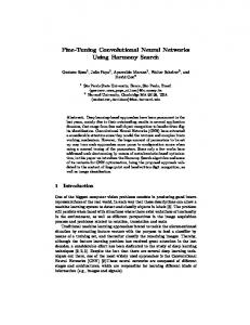
The received signal is sent to an Intermediate Frequency (IF) demodulator and than to a non-coherent Delay Lock Loop. The DLL is based on the correlation between the received signal and five locally generated code replicas: Very Early (VE), Early (E), Prompt (P), Late (L) and Very Late (VL). The distance between the replicas (spacing) is a basic feature in precision positioning. A discriminator is used to find the correlation maximums. The general receiver architecture can be seen in Figure 1.
PREAMPLIFIER
X
CODE TRACKING & SYNCHRONIZATION MODULE
PHASE TRACKING MODULE
Figure 1 General receiver architecture
(1) The discriminator is an error function that depends on the correlation function. The error function shows that when the error is greater then zero the replica must be delayed, otherwise the replica must be anticipated. If the error function is zero the signal has declared synchronized. The chosen discriminator function in this paper is the Early minus late envelope normalized function and it is described by the following equation (4)
D=
2 2 2 2 I VE + QVE + I E2 + QE2 − I L2 + QL2 − I VL + QVL 2 2 2 2 I VE + QVE + I E2 + QE2 + I L2 + QL2 + I VL + QVL
(4)
M
¦ a i g i (t − τ i ) + η (t )
IF DEMODULATOR
NAVIGATION DATA PROCESSING
where: • a represents the attenuation coefficient • d and s are, respectively, the signal and spreading code • τ is the delay of the signal • φ is the carrier phase • η ( t ) represents the gaussian noise In presence of multipath (i.e.: a distorted signal arrives at the receiver via multiple paths due to reflections from the Earth and nearby objects) [6], instead, M different paths have to be considered. So the received signal can be rewritten as follows:
r (t ) = a 0 g (t ) +
DLL TRACKING SYSTEM
(2)
where IVE, IE, IL, IVL, QVE, QE, QL and QVL represent the very early, early, late and very late correlation values for the in phase and quadrature component of the received signal. This function has been chosen, even if it is characterized by a high computational cost, because it achieves the best performance in the gaussian environment [7]. From the receiver point of
i =1
where: • ai represents the i-th attenuation coefficient • gi represents the delayed replica of the i-th signal replica • M is the total number of reflections • τ i is the delay of each path 370
view the discriminator’s output is the feedback signal to control the local code replica. IV.
fact, to improve the synchronization using the available information making the system channel adapted in real time.
NEURAL NETWORKS-BASED TRACKING
A
The proposed solution is to use the neural network instead of the Early minus late envelope normalized function. The neural networks have many possible applications and useful characteristics for the analyzed problems: structure based on simple units, the neurons; capacity to extract common characteristics by the input data and capacity to divide the input features on the basis of the common characteristics. The neural networks-based tracking follows the principle that the neural networks systems have great performance as classifiers and the classical discriminator function operates, in fact, a classification among three described situations (anticipate, delay and synchronize). Neural networks are based on simple computational units called artificial neurons and whose equations are the following [10]:
The NN learning is an important aspect. The NN, in fact, a priori are not able to make their tasks. They have to learn the fundamental notion by the environment. There are different techniques to train a network. A classical division is between Supervised Learning and Unsupervised Learning. In the former during the training phase the network needs of a “teacher”. For every training vectors, like the real vectors used by the networks, the known correct output have to be presented (the so called “learning with a teacher” paradigm [10]). In this manner the networks have a certain number of correct examples and on their base learn as work in the following time. In the Unsupervised Learning there is no teacher that verifies the learning process; the network modifies its parameters by itself. In this case the system is able to subdivide in autonomy its inputs into a number of output classes decided by the user [10].
m
u k = ¦ w kj x j
(5)
y k = ϕ (u k + bk )
(6)
Learning
j =1
B
The Self Organizing Map
The SOM are based on unsupervised learning. This is important to track a code in a wireless channel. No information about the real synchronization is available. In these cases a training phase with a valid training set is useful. These types of network are based on the competitive learning: the every neuron competes with others following the strategy of winner-takes-all. The active neuron is called winning neuron. In a SOM the neurons are positioning at the knots of a grid usually one or two dimensions. The position of the winning neurons is modified to create a topographic map. The neuron coordinates are characteristics of the input. The learning process is based on different phases after an initialisation: Competition, Cooperation and Synaptic Adaptation. During the competition phase a discriminate function is calculated when an input is presented. The winning neuron is the neuron with the higher value. In the cooperation phase, the winning neuron causes a spatial position with active neurons and cooperates with the neighbours. In the Synaptic Adaptation the winning neuron and its neighbours change their synaptic weights on the basis of the presented input.
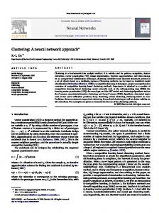
where xj are the input signals, wkj are the synaptic weights (for the connection between the j-th input and the k-th neuron of the second layer), ϕ ( ) the activation function, bk the biases and yk the outputs. A representation of an artificial neural network is shown in Figure 2.
Figure 2 Artificial neuron representation [10]
In a neural network system the input information can be organized in a more complex way than with simple linear thresholds, so five different crosscorrelation measurements have been used as input data to be processed by the system in order to decide for the correct class, that is to say the output. The aim is, in
V.
RESULTS
In order to validate the better performance of the realized code tracking system many simulation 371
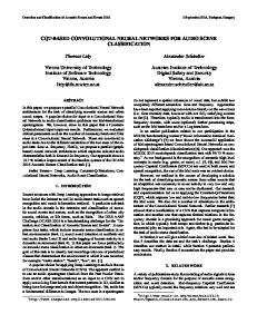
sessions have been carried out. The results have been reached with a complete 4-channel Galileo/GPS transmission system in a MATLAB™ SIMULINK™ 6.0 environment. The created simulation environment is able to considerate different set of parameters, especially about the multipath characteristics. Every single test represents a period of 30 ms of transmission (30 code epochs). The simulations have been made in case of time-variable multipath. In particular four different multipath environments, characterised by the presence of 3, 5, 7 and 9 paths, have been tested. The test results have been evaluated in terms of: Synchronization loss frequency Mean number of synchronization evaluation errors. For the first estimation the case in which the system looses synchronization is considered. The results are made with the number of cases in which the signal escapes from the correction capabilities of the system. In the following figure (Figure 3) the synchronisation loss is shown.
Figure 4 Synchronization evaluation errors
The second kind of evaluation comes from the observation that, even when the code tracking system corrects the time shift between the signal and the local code, it sometimes takes wrong decisions about the signal condition but usually, if the system works well, it comes back to the right timing at the following period. These errors influence only the stability of the tracking and cause a little error on the position evaluation of the GPS. These results are depicted in the Figure 4. Also in this case the performance improvement passing from DLL to a SOM neural network is evident. VI.
CONCLUSIONS
This study demonstrates that the use of neural networks classifiers in the code tracking is a promising technique. Simulation tests have had shown a clear improvement of the DLL performance concerning synchronization error frequency and estimation precision. Therefore the SOMs are able to give an improvement to classical techniques, through a modest increase of the computational load. Possible improvements could be made adding the adaptability to the real-time channel variations, ensuring the best possible synchronization stability.
Figure 3 Synchronization loss frequency
Two different type of SOM are evidenced. The first one is trained by an AWGN channel pattern set, the other one have a training set deriving by multipath channel pattern. The performance improvement going from the curve representing DLL to the solid curve, representing the SOM discriminator trained by multipath channel training set, is evident.
VII.
REFERENCES
[1] Elliot D. Kaplan (Editor), ‘Understanding GPS: Principles and Applications’, Artech House Telecommunications Library, 1996.
[2] Van Dierendonck, A.J., ‘Theory and Performance of Narrow Correlator Spacing in a GPS Receiver’, Navigation: Journal of The Institute of Navigation, vol.39, No.3, Fall 1992.
[3] European Commission, “Galileo-Mission High Definition”, Doc. EMRF 5/5/2 (Pt.2), ESA, April 2001
372
Level
[4] Guenter W. Hein and Bernd Eissfellen “Galileo designe options for the european GNSS – 2”
[5] G.W. Hein, J. Godet, J.L. Isseler, J.C. Martin, R.L. Rodriguez, T. Pratt, “Status of Galileo frequency and signal design”, September 2002 [6] J.G. Proakis, “Digital communications”, Mc Graw Hill International Editions, third edition, 1995 [7] Parkinson W., J.J. Spilker Jr ’Global Position System: Theory and Applications’ – volume 1, Editor Axelrad – Enge, 1996
[8] John W. Betz “The Offset Carrier Modulation for GPS Modernization”, The MITRE Corporation [9] P. Fine and W. Wilson, “Tracking Algorithm for GPS Offset Carrier Signals”, Proceedings of the Institute of Navigation, 1999 National Technical Meeting, January 1999 [10] Haykin S., “Neural Networks, a Comprehensive Foundation”second edition, Prentice Hall International, 1999 [11] B. R. Townsend, P. C. Fenton, K. J. Van Dierendonck, “Ll Carrier Phase Multipath Error Reduction Using MEDLL Technology”, 1ON GPS-95, Palm Springs, CA, September 1995 [12] M. C. Laxton, S. L. DeVilbiss, “GPS Multipath Mitigation During Code Tracking”, Proceedings of the American Control Conference, Albuquerque, New Mexico, June 1997 [13] A. Cichra, R. Kaufmann, M. Sust, “Comparison of global navigation satellite system receiver multipath mitigation techniques”, GNSS-03 conference, 22-25 April 2003, Graz Austria
373