Manoonpong, P.; Pasemann, F.; Fischer, J. & Roth, H. / Neural Processing of Auditory Signals and Modular Neural. Control for Sound Tropism of Walking Machines. Preprint: to appear in International Journal of Advanced Robotic Systems, Volume 2, Number 3 (2005), ISSN 1729-5506
Neural Processing of Auditory Signals and Modular Neural Control for Sound Tropism of Walking Machines Poramate Manoonpong1; Frank Pasemann1; Joern Fischer1 & Hubert Roth2 1
Fraunhofer Institut Autonome Intelligente Systeme, Sankt Augustin, Germany, poramate.manoonpong,
[email protected] 2 Institut für Regelungs und Steuerungstechnik (RST), Elektrotechnik und Informatik, Siegen, Germany,
[email protected]
Abstract: The specialized hairs and slit sensillae of spiders (Cupiennius salei) can sense the airflow and auditory signals in a low-frequency range. They provide the sensor information for reactive behavior, like e.g. capturing a prey. In analogy, in this paper a setup is described where two microphones and a neural preprocessing system together with a modular neural controller are used to generate a sound tropism of a four-legged walking machine. The neural preprocessing network is acting as a low-pass filter and it is followed by a network which discerns between signals coming from the left or the right. The parameters of these networks are optimized by an evolutionary algorithm. In addition, a simple modular neural controller then generates the desired different walking patterns such that the machine walks straight, then turns towards a switched-on sound source, and then stops near to it. Keywords: recurrent neural networks, neural control, auditory signal processing, autonomous robots, walking machines
1. Introduction Sensors and sensing are significant for specific behaviors or actions of an animal. For instance, the wandering spider (Cupiennius salei) preys on a flying insect by using the special sensory hair (Trichobothria) (Barth, F.G., 2002), (Keil, T., 1997), (Uetz, G.W. & Roberts, J.A., 2002) on its limbs to detect the airflow and the auditory cues in a low-frequency range between approximately 40 and 600 Hz (Barth, F.G. & Geethabali, 1982), (Barth, F.G. & Wastl, U. & Humphrey, J.A.C. & Devarakonda, R., 1993). It orients its movement towards the direction of the signal and then jumps to the targeted buzzing fly. This is known as “prey capture behavior” (Barth, F.G. & Humphrey, J.A.C. & Secomb, T.W., 2003), (Hergenröder, R. & Barth, F.G., 1983). To observe the functioning of a corresponding artificial perception-action system in robots we simply replace the puff of the wind; normally generated by the buzzing fly, by a low-frequency sound around 200 Hz. A soundinduced behavior is called “sound tropism”, if, as a result, the walking machine reacts to a switched-on
sound source by turning towards and making an approach at the end. There are several examples of experiments with robots that use auditory signal processing and sound localization. Most of the research focuses on the crosscorrelation technique (Briechle, K. & Hanebeck, U.D., 1999), (Omologo, M. & Svaizer, P., 1994) to perform auditory source localization by using an array of four or more microphones (Aarabi, P. & Wang, Q.H. & Yeganegi, M., 2004), (Murray, J. & Erwin, H. & Wermter, S., 2004), (Svaizer, P. & Matassoni, M. & Omologo, M., 1997), (Valin, J.M. & Michaud, F. & Rouat, J. & Létourneau, D., 2003), (Wang, Q.H. & Ivanov, T. & Aarabi, P., 2004). There are other examples, for instance, the SAIL robot uses the microphone for online learning of verbal commands (Zhang, Y. & Weng, J., 2001); and a humanoid robot called ROBITA, which uses two microphones to follow a conversation between two persons (Matsusaka, Y. & Kubota, S. & Tojo, T. & Furukawa, K. & Kobayashi, T., 1999). In addition, principle engineering techniques, e.g. a Fast Fourier Transformation or diverse filter techniques
XX
(Coulter, D., 2000), including specialized digital signal processors (DSP) are frequently used to analyze the auditory data. Often these methods are too slow to generate a reactive action of machines, too complex, and too expensive to achieve the optimal performance. However, in other articles from the domain of biologically inspired robotics the behavior generated by auditory signals is studied (Horchler, A. & Reeve, R. & Webb, B. & Quinn, R., 2003), (Reeve, R. & Webb, B., 2003), (Webb, B. & Harrison, R., 2000), (Webb, B. & Scutt, T., 2000). They implemented neural models of sound localization for robot phonotaxis allowing the robot to detect and move towards a simulated male cricket song-4.8 kHz (Lund, H. H. & Webb, B. & Hallam, J., 1998), (Michelsen, A. & Popov, A.V. & Lewis, B., 1994). Inspired by the described behavior of the spider Cupiennius salei, we apply the neural network for auditory signal processing described in (Manoonpong, P. & Pasemann, F. & Fischer, J., 2004) which has been developed to operate in a low-frequency range up to around 300 Hz. Here, this so-called “advanced auditory network” is implemented together with the auditory sensor system on the four-legged walking machine AMOS-WD02. In addition, this setup is combined with a so-called “sound-direction detection network” which detects the direction of the sound source. Both networks are developed and optimized via an evolutionary algorithm. Together with the modular neural controller, this will enable the autonomous walking machine to react on the specific auditory signal, and to move in the direction of the sound source in a real environment. The paper is organized as follows. Section 2 describes the perception-action system which generates the sound tropism. Section 3 explains the simple neural network for preprocessing the sensor signals. It performs as a lowpass filter and at the same time is able to discern between directions of the sound source. For that, time delay of arrival (TDOA) of signals coming from auditory sensors based on the fore left and rear right legs is used. In section 4, a modular neural controller is introduced. This controller generates the walking pattern and executes sound tropism. Experiments and their results are discussed in section 5. Conclusions and an outlook on future works are given in the last section. 2. The perception-action system Describing the machine together with its behavior as a perception-action system, one can identify four different parts (compare Fig. 1). First, there are two microphones acting as auditory sensors in analogy to the hairs of the spiders. Second, there is the network preprocessing the auditory signals. Then, there is the modular neural network controlling the behavior of the walking machine. Finally, we have to take into account the physical properties of the machine.
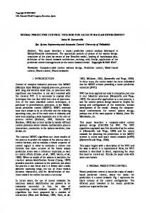
Fig. 1. The perception-action system. 2.1. An auditory sensor system The auditory sensor system consists of two miniature microphones (0.6 cm diameter) installed on the (moving) fore left and rear right legs of the walking machine. They have a separation of 42 cm (see Fig. 2).
Fig. 2. The auditory sensor system. (A) The distance between two sensors is equal to 42 cm. (B) One real sensor built in a preamplifier circuit is installed on the fore left leg of the walking machine. Consequently, these sensors can scan the auditory signals in the wider angle because they are moving with the legs. The signals are amplified via the microphones’ integrated amplifier circuit, and then scaled to the range between 0 and 5 V by an extra electronic circuit board. Afterwards, they are sampled via analog to digital converter (ADC) channels of the Multi-Servo IO-Board (MBoard)1. 1
For more details see http://www.ais.fraunhofer.de/BE/volksbot/mboard.htm
YY
2.2. The walking machine AMOS-WD02 To explore the performance of the auditory sensor system in a real environment, a robot platform is required, and because of the biologically inspired approach we prefer a morphology which is similar to that of walking animals. Inspired by the morphology of the reptiles’ trunk and its motion, we design the four-legged walking machine AMOS-WD02 with a backbone joint at the trunk, which facilitates more flexible and faster motion. The trunk is composed of the backbone joint which can rotate vertically, four identical legs, each with two degrees of freedom, and an active tail with two degrees of freedom rotating in the horizontal and vertical axes (see Fig. 3).
Fig. 3. The four-legged walking machine AMOS-WD02. All leg joints are driven by analog servo motors producing a torque between 70 and 90 Ncm. The backbone joint is driven by a digital servo motor with a torque between 200 and 220 Ncm. For the active tail, micro-analog servo motors with a torque around 20 Ncm are selected. The height of the walking machine is 12 cm without its tail. Its weight is approximately 3 kg. On the active tail, a mini wireless camera with built in microphone is installed for monitoring and observation while the machine is walking. All in all AMOS-WD02 has 11 active degrees of freedom and therefore it can serve as a reasonably complex platform for experiments concerning the function of a neural perception-action system. To have a completely mobile system, a Personal Digital Assistant (PDA) is installed on the walking machine. It is used for programming the neural processing and the neural controller, and for communicating with the Multi-Servo IO-Board (MBoard) via a RS232 interface. 3. An artificial neural auditory signal processor The approach to signal processing uses dynamical properties of recurrent neural networks. The standard additive neuron model with sigmoidal transfer function together with its time-discrete dynamics is given by n
ai (t + 1) = Bi + ∑Wij tanh(a j (t )) i = 1,..., n ,
(1)
j =1
where n denotes the number of units, ai their activities, Bi
represents a fixed internal bias term together with a stationary input to neuron i, and Wij synaptic strength of the connection from neuron j to neuron i. The output of neurons is given by the sigmoid oi = tanh (ai). Input units are configured as linear buffers. The desired network as an artificial neural auditory signal processor is composed of two subordinate networks, one for filtering auditory signals to detect the low-frequency sound, and another to distinguish the detected signals between the right and the left. Later the outputs of this network will activate the corresponding reactive behavior of the walking machine. 3.1. A low-pass filter for auditory signals acting in a real environment In order to directly filter the sampled signals from ADC channels of the MBoard, the simple model neurons are configured as a hysteresis element (Pasemann, F., 1993a). In (Manoonpong, P. & Pasemann, F. & Fischer, J., 2004) it is demonstrated that the network, called “advanced auditory network”, behaves similarly to a low-pass filter circuit. It passes signals of sine shape in a frequency range between 50 and 300 Hz. There, the auditory signals were recorded via an artificial auditorytactile sensor and the output signal was sampled through the line-in port of a sound card at a sampling rate of 48 kHz. The network ran on a 1 GHz personal computer. Here, the auditory signals are sampled via the MBoard at a sampling rate of 5.7 kHz, and the network is programmed on the PDA. For using on the walking machine, the parameters (weights and a bias) of the advanced auditory network have to be recalculated. An evolutionary algorithm, the ENS3-algorithm (Evolution of Neural Systems by Stochastic Synthesis (Hülse, M. & Wischmann, S. & Pasemann, F., 2004)), is applied to optimize the parameters of this network. The first population consists of the fixed network shown in Fig. 4A, and the evolutionary process is running until a reasonable solution is reached. The fitness function F which minimizes the square error between target and output signals is given by
F=
10 1+ E
.
(2)
For the ideal case, the maximum value of F should be 10 while the mean squared error E should be equal to 0. The mean squared error E is evaluated by the equation:
E=
1 N ∑ (t arg et (t ) − output (t ))2 , N t =1
(3)
where N is the maximal number of time steps. In this case it is set to N = 6000. The target signal is activated by oscillating between +1 and -1 if and only if a lowfrequency signal from 100 to 400 Hz is presented and it is -1 in all other cases. This is exemplified in Fig. 4B and C.
XX
Fig. 4. (A) An initial network structure with given weights and a bias. (B) The varying frequencies of an input signal from 100 Hz to 1000 Hz coming from a physical sensor. (C) A corresponding target signal. After 55 generations the resulting network had a fitness value of F = 8.76, which is sufficient to recognize the low-frequency signals. This is shown in Fig. 5. This preprocessing network can filter the noises at high frequencies (>400 Hz) which might occur from the motors of the walking machine during walking and standing. 3.2. A sound-direction detection network To discern the direction of the auditory signals for sound tropism, the mentioned ENS3-evolutionary algorithm is again applied to find the appropriate neural network based on the concept of the time delay of arrival (TDOA). According to the dimension of the walking machine and the distance between the fore left and rear right sensors, the maximum time delay between the left and the right is equivalent to one-fourth of the wavelength of the carrier frequency which is 200 Hz.
YY
Fig. 5. (A) The advanced auditory network which is optimized by the evolutionary algorithm. It is able to filter the frequency of the auditory signals which is higher than 400 Hz. (B) The output signal of the network. In the smashed frame, there are auditory signals in a low-frequency range approximately between 100 and 400 Hz. (C) The characteristic curve of this network with its cutoff frequency at around 400 Hz.
To evolve the neural network, the same strategy as described before is applied. The initial neural structure is now based on the minimal recurrent controller (MRC) (Hülse, M. & Pasemann, F., 2002), and its parameters are shown in Fig. 6A. This neural structure consists of two input and two output neurons. The input signals are detected by the left and right sensors and these signals are firstly filtered via the advanced auditory network; i.e. only noise-free signals at the low frequencies can pass through the evolved network. The input signals together with the delay of each are shown in Fig. 6B. The fitness function F is determined by equation (2), and the squared error E is estimated by
E=
1 N
N
2
∑ (∑ (t arg eti (t ) − output i (t )) 2 ) . t =1
(4)
i =1
N is equal to 3500 referring to the maximal number of time steps and i = 1, 2 refers to the signals on the right and the left respectively. The target signals are prepared in such a way that they refer to recognition of a leading signal or to only one active signal. For instance (see Fig. 6C), Target1 (full line) is set to +1 if the signal of Input1 (I1) leads the signal of Input2 (I2) or only I1 is active indicating “the sound source is on the right side” and it is set to -1 in all other cases. Correspondingly Target2 (smashed line) is set to +1 in the reversed cases indicating “the sound source is on the left side”.
Fig. 6. (A) An initial network structure with given weights. (B) The input signals—after filtering via the advanced auditory network—at the frequency of 200 Hz from the right (full line) and left (smashed line) sensors involving a delay between them. (C) Target1 (full line) and Target2 (smashed line) corresponding to the direction of the signals on the right and the left, respectively.
The network resulting from the evolution after 260 generations has a fitness value F = 6.96 which is sufficient to solve this problem. This sound-direction detection network as well as the input and output signals are presented in Fig. 7.
Fig. 7. (A) The resulting network called “sound-direction detection network”. (B) The input signals from both sensors with the delay between each other. At the first period, the sound source is on the right of the walking machine while after around 110 time steps it changes to the left. (C) During the first period, the signal of Output1 is active and the signal of Output2 is inactive while after 110 time steps the signal of Output1 becomes inactive and the signal of Output2 becomes active. The main feature of this network is its ability to distinguish the direction of incoming signals by observing a leading signal or solely an active signal. Furthermore, it is easy to implement on the mobile system because of its uncomplicated structure.
XX
In addition, its outputs can directly be connected to the neural control module such that it determines the walking direction of the machine; e.g. the machine turns left when the sound source is on the left side and vice-versa. The output neurons of this small network are excited by straight and cross connections coming from each of the input neurons. There are also excitatory self-connections at both output neurons providing hysteresis effects; i.e. they allow the switching between two fixed point attractors corresponding to stationary output values of the output neurons, one low the other high (see Fig. 8). The strength of a self-connection w > +1 determines the width of the hysteresis interval in the input space (Hülse, M. & Pasemann, F., 2002). However, if the strength of w is too large (for instance, the weight at Output1 w1 > 2.0 and at Output2 w2 > 3.5), then the inputs will not cross the hysteresis domains to and fro, and the output signal will oscillate around the high output value if the input signal is activated. This is demonstrated in Fig. 8 where Output2 versus Input2 for smaller self-connection weights (w1 = 2.0, w2 = 3.5) and larger self-connection weights (w1 = 2.206, w2= 3.872) are plotted.
Fig. 8. Comparing outputs for different self-connection weights at Output1 and Output2 while I2 sweeps over the input interval (-1 and +1) and I1 is given by following Input2 with a delay. (A) Varying Output2 for smaller self-connection weights (w1 = 2.0, w2 = 3.5), and (B) for stronger self-connection weights (w1 = 2.206, w2 = 3.872). Black spots indicate the initial output values, which are then following the indicated paths (dot line). There is no hysteresis loop in (B) like it is in (A); instead it oscillates around the high output value.
YY
Fig. 8A shows the switching of the output of Output2 (O2) between almost saturation values (corresponding to the fixed point attractors) while I2 varies over the whole input interval and I1 is provided with a delay (see Fig. 9A). O2 in Fig. 8B jumps and then stays oscillating with very small amplitude around the high output value. Moreover, one can also see this effect in Fig. 9. The output signals corresponding to the different strengths of the self-couplings are plotted for w1 = 2.0, w2 = 3.5, and for the original weights, i.e. w1 = 2.206, w2 = 3.872 (compare Fig. 7A). Here the sound source is on the left side causing I1 to follow I2 with a delay (see Fig. 9A). Also, the output of Output1 (O1) is suppressed while O2 is activated (see Fig. 9B and C).
Fig. 9. (A) The input signals with a delay. (B) shows the corresponding oscillating O2 (smashed line) for the smaller self-connection weights (w1 = 2.0, w2 = 3.5) while O1 is suppressed. (C) shows that O2 is higher than a threshold (here 0.5) for stronger self-connection weights (w1 = 2.206, w2 = 3.872). For the smaller self-connection weights, O2 oscillates between the low value (around -1) and the high value (around +1) as shown in Fig. 9B. For the larger selfconnection weights, O2 oscillates finally with a very small amplitude around the high value above a threshold, e.g. 0.5 (compare Fig. 9C).
Furthermore, the output neurons form a so-called even loop (Pasemann, F., 1993b); i.e. they are recurrently connected by inhibitory synapses (see Fig. 7A). This configuration guaranties that only one output at a time can be positive, i.e. it functions as a switch, sending the output to a negative value for the delayed input signal. The output signals of this phenomenon can be observed in Fig. 7C. By utilizing these phenomena of the larger selfconnection weights and the even 2-module, one can easily apply the output signals to control the walking direction of the machine. 3.3. An auditory signal processing network Here, the integration of the advanced auditory network and the sound-direction detection network leads to the conclusive auditory signal processing network (see Fig. 10).
The sound-direction detection network then indicates the direction of the corresponding signals. Subsequently, the output neurons of the sound-direction detection network will be connected to the modular neural controller to make the walking machine turn into the appropriate direction. Eventually, the walking machine will approach and stop nears the source by determining a threshold of the amplitude of the auditory signals. 4. The modular neural controller for reactive behavior The modular neural controller consists of two subordinate networks which are a neural oscillator network generating the rhythmic leg movements, and the velocity regulating network (VRN) which expands the steering capabilities of the walking machine (Manoonpong, P. & Pasemann, F. & Fischer, J., 2005). 4.1 Neural oscillator network for rhythmic locomotion The concept of neural oscillators for walking of machines has been studied e.g. by Hiroshi Kimura (Kimura, H. & Sakurama, K. & Akiyama, S., 1998). There, a neural oscillator network with four neurons is constructed by connecting four neural oscillator’ s, each of which drives the hip joint of one of the legs. Here we use a so-called SO(2)—network (Pasemann, F. & Hild, M. & Zahedi, K., 2003) to generate rhythmic locomotion. It has already been implemented successfully as central pattern generator (CPG) in the six-legged walking machine Morpheus (Fischer, J. & Pasemann, F. & Manoonpong, P., 2004). The same structure and weights are applied to control the four-legged walking machine AMOS-WD02. The network consists of two neurons (compare Fig. 11A), where the sinusoidal outputs of these oscillating elements are signals corresponding to a quasi-periodic attractor. They drive the motors directly for generating the locomotion. This network is implemented on a PDA having an update frequency of 25.6 Hz and it generates a sinusoidal output with a frequency of approximately 0.8 Hz (see Fig. 11B). 4.2 The velocity regulating network
Fig. 10. The auditory signal processing network which functions as a low-pass filter circuit and which has ability to detect the directionality of the corresponding signals. This network has the ability to filter the auditory signals and to discern the direction of the input signals. First, the sensory inputs (Auditory Input1 and Auditory Input2 in Fig. 10) are filtered by the advanced auditory network so that only low-frequency sounds can pass. Secondly, the outputs from the advanced auditory network are connected to the inputs of the sound-direction detection network.
To change the motions, e.g. from walking forwards to turning left and right, the simplest way is to perform a 180 degree phase shift of the sinusoidal signals which drive the thoracic joints. To do so, we introduce the velocity regulating network (VRN) (Fischer, J., 2004) which performs a multiplication of two input values x, y ∈[-1, 1]. For our purpose the input x is the oscillating signal coming from the SO(2)—network, and the input y is the sensory signal coming from the auditory signal processing network. Fig. 12A presents the network consisting of four hidden neurons and one output neuron. Fig. 12B shows that the output signal gets a phase shift of 180 degrees, when the sensory signal (input y) changes from -1 to 1.
XX
4.3 The modular neural controller The combination of two neural networks (the neural oscillator network and the velocity regulating network) leads to an effective modular neural controller to perform a sound tropism. One oscillating output signal from the SO(2)—network is directly connected to all basal joints, while another one is connected to the thoracic joints only indirectly, passing through all hidden neurons of the VRN through the so called x–input (see Fig. 12A). The output signals of the auditory signal processing network go to Input1 and Input2 of the VRN (compare Fig. 10 and 13). Thus, the rhythmic leg movements are generated by the SO(2)—network and the steering capabilities of the walking machine are realized by the VRN in accordance with the outputs of the auditory signal processing network. The structure of this controller and the location of the corresponding motor neurons on the walking machine are shown in Fig. 13. Fig. 11. (A) The structure of the SO(2)—network with the synaptic weights for our purpose. B1 and B2 are bias terms with B1 = B2 = 0.01. (B) The output signals of neurons 1 (smashed line) and 2 (full line) from the SO(2)—network. The output of neuron 1 is used to drive all thoracic joints and one backbone joint as well as the output of neuron 2 is used to drive all basal joints.
Fig. 12. (A) The VRN with four hidden neurons and the given bias terms B which are all equal to -2.48285. (B) The output signal (full line) when the input y is equal to +1 and the output signal (smashed line) when the input y is equal to -1 while input x is the oscillating signal coming from the SO(2)—network.
YY
Fig. 13. This is the modular neural controller. It generates a trot gait by the SO(2)—network (smashed frame) and it is modified when corresponding sound appears. The bias terms B of the VRN (solid frame) are all equal to -2.48285. Two outputs from the auditory signal processing network are directly connected to the input neurons (Input1, Input2) of this controller. If the
auditory signals are detected, the outputs of the auditory signal processing network make the walking machine turn because the VRN changes the quasi-periodic signals at the thoracic joints. By integrating the auditory signal processing network and the modular neural controller, the walking machine is able to react to a specific sound source, turn to it and finally approach it. 5. Experiments and results To test the capability of the composed system, auditory signal processing network and modular neural controller, for generating desired sound tropism in the walking machine, several experiments have been carried out. The sound signals were produced by a powered loudspeaker system (30 Watts). These signals were recorded and sampled at a sampling rate of 5.7 kHz via the auditory sensor system. The auditory signal processing network and the modular neural controller were programmed on a PDA (Intel (R) PXA255 processor). For the first experiment, the maximum distance at which the system is able to detect the auditory signals was measured. During the test, the signals were produced at the carrier frequency of 200 Hz and the walking machine was placed five times at each of the different locations (black square areas) shown Fig. 14.
Fig. 14. The experimental setup with the sound source and the markers (black square areas) where the walking machine was placed. The detection rates of the auditory signals, i.e. the number of correct detections2 divided by number of experiments, are shown in Table 1. Distance 40 cm. 60 cm. 80 cm.
Detection rate 100% 67% 0%
Table 1. Detection rate of auditory signals at 200 Hz from different distances
These results can be concluded that the system can reliably react to the auditory signals in the radius up to around 60 cm. The second task was to demonstrate the sound tropism in the real environment. The walking machine started from three different initial positions (on the left, on the right and in front of the sound source) and these specific auditory signals were generated as described before. Fig. 15 shows a series of photos of these example experiments3. At the beginning the machine walks forward and when the auditory signals are detected, the machine orients its movement into the direction of the source. After that it makes an approach until a threshold of the amplitude of the signals is reached. Finally, it stops nearby the sound source. From the experimental results, one can see that it does not always reach the sound source with its head pointing to the source, but sometimes with the side of the body. However, these approaching positions would not matter; if the walking machine reaches the sound source that is sufficient. And we conclude that the walking machine can successfully perform a sound tropism at the carrier frequency-200 Hz during walking in the distance up to around 60 cm. 6. Conclusions Inspired by the sensory system of the spider and its “prey capture behavior”, we stimulate a comparable behavior by a simple perception-action system. This system consists of an “auditory signal processing network” for detecting a low-frequency sound and its direction, and a “modular neural controller” to execute reactive behavior of the physical walking machine displaying a sound tropism. Using the auditory sensor system in analogy to the hairs of the spiders the sound is preprocessed by a network composed of a so-called “advanced auditory network” acting as a low-pass filter, and a “sound-direction detection network” which discerns the direction of the signals. Both networks have been optimized by an evolutionary algorithm. Furthermore, to generate the locomotion and the appropriate change of the walking pattern, the “modular neural controller” is applied. This controller is constructed by a 2-neuron oscillator network acting as a pattern generator, and the “velocity regulating network” (VRN). The described walking machine then can detect auditory signals at a carrier frequency of 200 Hz in distance up to approximate 60 cm. We demonstrated that the walking machine recognizes the signals coming from the left or the right. It turns into the direction of the sound source then approaches, and finally it will stop besides the source in a distance determined by a threshold of the amplitude of the signals. ………
2
Correct detections mean that the machine can correctly discern if the signals are coming from the left or the right.
3
For more demonstrations see http://www.ais.fraunhofer.de/~poramate
XX
Fig. 15. Examples of the sound tropism. (A) The walking machine is able to react to the signals coming from the left and it will stop near the source at the end. The walking trajectory is drawn in the lower picture. (B) The walking machine is placed in front of the source at the distance of 80 cm. At the beginning, it walks forward and turns toward the sound source when it can hear and then it will stop beside the source. The trajectory from the starting position to the end position is drawn in the lower picture. (C) If the signals can be heard from the right, then the walking machine will turn right, make an approach to the sound source and stop beside it. Also, the lower picture shows the trajectory of its walking. The demonstrated sound tropism is a positive tropism which causes the machine to turn toward the source like a predator reacting to the signal of a prey. Anyhow, one can apply this system also for a negative tropism meaning that the machine runs away from the sound
YY
source like a prey fleeing from the sound of a predator. However, the described perception-action system can be improved by integrating more reasonable behaviors, for instance an exploration and an obstacle avoidance behavior.
In a next step, we will implement infrared sensors together with an additional preprocessing network to achieve a more complex behavior of the walking machine. Eventually, all these different preprocessor and controllers will be merged into one modular neural network, where the parts have to cooperate or to complete to form versatile intelligent perception-action systems. ACKNOWLEDGEMENT The Integrated Structure Evolution Environment (ISEE) software platform for the evolution of recurrent neural networks was provided by Keyan Zahedi, Martin Hülse, and Steffen Wischmann of FhI-AIS. 7. References Aarabi, P.; Wang, Q.H. & Yeganegi, M. (2004). Integrated Displacement Tracking And Sound Localization, Proceedings of the 2004 IEEE Conference on Acoustics, Speech, and Signal Processing (ICASSP 2004), Montreal, May Barth, F.G. (2002). A Spider's World: Senses and Behavior, Springer Verlag, ISBN: 3-540-42046-0 Barth, F.G. & Geethabali (1982). Spider Vibration Receptors Threshold Curves of Individual Slits in the Metatarsal Lyriform Organ, Journal of Comparative Physiology. A, Vol. 2, pp. 175-186 Barth, F.G.; Humphrey, J.A.C. & Secomb, T.W. (2003). Sensors and Sensing in Biology and Engineering, Springer Verlag, Wien Barth, F.G.; Wastl, U.; Humphrey, J.A.C. & Devarakonda, R. (1993). Dynamics of Arthropod Filiform Hairs-II: Mechanical Properties of Spider Trichobothria (Cupiennius salei), Philosophical transactions of royal Society of London B, 340, pp. 445-461 Briechle, K. & Hanebeck, U.D. (1999). Self-localization of a Mobile Robot Using a Fast Cross-correlation Algorithm, Proceedings of the 1999 IEEE Systems, Man, and Cybernetics Conference (SMC'99), Tokyo, Japan Coulter, D. (2000). Digital Audio Processing, CM Books, KS, USA Fischer, J. (2004). A Modulatory Learning Rule for Neural Learning and Metalearning in Real World Robots with Many Degrees of Freedom, Ph.D. Thesis, University of Muenster, Shaker Verlag GmbH, ISBN 3-8322-2543-9 Fischer, J.; Pasemann, F. & Manoonpong, P. (2004). Neuro-Controllers for Walking Machines-an evolutionary approach to robust behavior, Proceedings of 7th International Conference on Climbing and Walking Robots (CLAWAR’ 04) Hergenröder, R. & Barth, F.G. (1983). Vibratory signals and spider behavior: How do the sensory inputs from the eight legs interact in orientation?, Journal of Comparative Physiology A, pp. 361-371
Horchler, A.; Reeve, R.; Webb, B. & Quinn, R. (2003). Robot phonotaxis in the wild: A biologically inspired approach to outdoor sound localization, Proceedings of 11th International Conference on Advanced Robotics (ICAR’ 2003), Coimbra, Portugal Hülse, M. & Pasemann, F. (2002). Dynamical Neural Schmitt Trigger for Robot Control, ICANN 2002, Dorronsoro J.R. (Ed.), LNCS 2415, Springer Verlag, Berlin Heidelberg New York, pp. 783-788 Hülse, M.; Wischmann, S. & Pasemann, F. (2004). Structure and function of evolved neuro-controllers for autonomous robots, In: Special Issue on Evolutionary Robotics, Connection Science, Vol. 16, No. 4, pp. 249-266 Keil, T. (1997). Functional morphology of insect mechanoreceptors, Microscopy research and Technique, pp. 506-531 Kimura, H.; Sakurama, K. & Akiyama, S. (1998). Dynamic Walking and Running of the Quadruped Using Neural Oscillator, Proceedings of IEEE/RSJ International conference on Intelligent Robots and Systems (IROS), pp. 50-57 Lund, H.H.; Webb, B., & Hallam, J. (1998). Physical and temporal scaling considerations in a robot model of cricket calling song preference, Artificial Life, 4(1), pp. 95-107 Manoonpong, P.; Pasemann, F. & Fischer, J. (2004). Neural Processing of Auditory-tactile Sensor Data to Perform Reactive Behavior of Walking Machines, Proceedings of MechRob2004, IEEE International Conference on Mechatronics and Robotics, Part 1, pp. 189-194, Aachen, Germany Manoonpong, P.; Pasemann, F. & Fischer, J. (2005). Modular neural control for a reactive behavior of walking machines, Proceedings of the CIRA2005, The 6th IEEE Symposium on Computational Intelligence in Robotics and Automation, Helsinki University of Technology, Finland, 27 - 30 June 2005 Matsusaka, Y.; Kubota, S.; Tojo, T.; Furukawa, K. & Kobayashi, T. (1999). Multi-person Conversation Robot using Multi-modal Interface, Proceedings of World Multiconference on Systems, Cybernetic and Informatics, Vol.7, pp. 450-455 Michelsen, A.; Popov, A.V. & Lewis, B. (1994). Physics of directional hearing in the cricket Gryllus bimaculatus, J. Comp. Physiol. [A], 175, pp. 153-164 Murray, J.; Erwin, H. & Wermter, S. (2004). Robotics Sound-Source Localization and Tracking Using Interaural Time Difference and Cross-Correlation, Proceedings of NeuroBotics Workshop, pp. 89-97, September, Ulm, Germany Omologo, M. & Svaizer, P. (1994). Acoustic Event Localization using a Crosspower-Spectrum Phase based Technique, Proceedings of IEEE ICASSP, Adelaide, Vol. 2, pp. 273-276 Pasemann, F. (1993a). Dynamics of a single model neuron, International Journal of Bifurcation and Chaos, Vol. 3, No.2, pp. 271-278
XX
Pasemann, F. (1993b). Discrete dynamics of two neuron networks, Open Systems and Information Dynamics, 2, pp. 49-66 Pasemann, F.; Hild, M. & Zahedi, K. (2003). SO(2)Networks as Neural Oscillators, Lecture Notes In Computer Science, Biological and Artificial computation: Methodologies, Neural Modeling and Bioengineering Applications, IWANN 7’th 2003 Reeve, R. & Webb, B. (2003). New neural circuits for robot phonotaxis, Philosophical Transactions of the Royal Society A, pp. 2245-2266 Svaizer, P.; Matassoni, M. & Omologo, M. (1997). Acoustic Source Location in a Three-dimensional Space using Cross-power Spectrum Phase, Proceedings of IEEE ICASSP, Munich, Germany Uetz, G.W. & Roberts, J.A. (2002). Multisensory cues and multimodal communication in Spiders: Insights from audio and video playback studies, Brain Behavioural Evolution, 59:4, pp. 222-230
YY
Valin, J.M.; Michaud, F.; Rouat, J. & Létourneau, D. (2003). Robust Sound Source Localization Using a Microphone Array on a Mobile Robot, IEEE/RSJ International Conference on Intelligent Robots and Systems, pp. 1228-1233 Wang, Q.H.; Ivanov, T. & Aarabi, P. (2004). Acoustic Robot Navigation Using Distributed Microphone Arrays, Information Fusion (Special Issue on Robust Speech Processing), Vol. 5, No. 2, pp. 131-140 Webb, B. & Harrison, R. (2000). Integrating sensorimotor systems in a robot model of cricket behaviour, Sensor Fusion And Decentralized Control, In Robotic Systems III, McKEE GT, Schenker PS, (Ed.), Proceedings of the Society of Photo-Optical Instrumentation Engineers (SPIE), 4196, pp. 113-124 Webb, B. & Scutt, T. (2000). A simple latency dependent spiking neuron model of cricket phonotaxis, Biological Cybernetics, pp. 247-269 Zhang, Y. & Weng, J. (2001). Grounded auditory development by a developmental robot, INNS/IEEE International Joint Conference on Neural Networks, pp. 1059-1064