1060 The Journal of Experimental Biology 213, 1060-1068 © 2010. Published by The Company of Biologists Ltd doi:10.1242/jeb.034678
Neuromechanical simulation of the locust jump D. Cofer1, G. Cymbalyuk2, W. J. Heitler4 and D. H. Edwards3,* 1
2
Departments of Biology, Physics and Astronomy and 3Neuroscience Institute, Georgia State University, Atlanta, GA 30303, USA and 4School of Biology, University of St Andrews, St Andrews, Fife, KY16 9TS, UK *Author for correspondence (
[email protected])
Accepted 29 November 2009
SUMMARY The neural circuitry and biomechanics of kicking in locusts have been studied to understand their roles in the control of both kicking and jumping. It has been hypothesized that the same neural circuit and biomechanics governed both behaviors but this hypothesis was not testable with current technology. We built a neuromechanical model to test this and to gain a better understanding of the role of the semi-lunar process (SLP) in jump dynamics. The jumping and kicking behaviors of the model were tested by comparing them with a variety of published data, and were found to reproduce the results from live animals. This confirmed that the kick neural circuitry can produce the jump behavior. The SLP is a set of highly sclerotized bands of cuticle that can be bent to store energy for use during kicking and jumping. It has not been possible to directly test the effects of the SLP on jump performance because it is an integral part of the joint, and attempts to remove its influence prevent the locust from being able to jump. Simulations demonstrated that the SLP can significantly increase jump distance, power, total energy and duration of the jump impulse. In addition, the geometry of the joint enables the SLP force to assist leg flexion when the leg is flexed, and to assist extension once the leg has begun to extend. Supplementary material available online at http://jeb.biologists.org/cgi/content/full/213/7/1060/DC1 Key words: locust, semi-lunar process, jumping, kicking, biomechanics, Hill muscle model, muscle, neuromechanical simulation, model, neural circuit, invertebrate.
INTRODUCTION
The ability to escape predators is of great evolutionary importance. Many animals, including the locust, have evolved to specialize in jumping as a method of escape and locomotion. The locust jump is mediated by neural and biomechanical mechanisms that first prepare the animal for the jump by storing mechanical energy in the legs, and then release it suddenly to catapault the animal into the air. Because of the impossibility of making the necessary measurements during a jump, the mechanisms have primarily been studied during a different behavior, the kick, when the locust body is held stationary (Heitler, 1988; Heitler and Burrows, 1977a; Heitler and Burrows, 1977b). The kick and the jump both involve rapid extension of the leg, but because the kick is unloaded, it occurs much more rapidly than the jump. Despite this difference, the similar neuromuscular activity before and during both behaviors has led to the suggestion that the kick and jump motor programs are the same (Heitler and Burrows, 1977a). The locust kick/jump motor program consists of three phases (Burrows, 1995; Heitler and Burrows, 1977a). The first phase is cocking the leg. The locust prepares for a jump by activating the flexor tibia muscle to bring the tibia into a fully flexed position. The second phase is a period of co-contraction where both the extensor and flexor tibia muscles are active. The extensor tibia muscle slowly contracts and stores energy in the extensor apodeme, in the semi-lunar process (SLP) and in the leg cuticle. As tension builds in the flexor tibia, its distal tendon passes over a cuticular invagination in the ventral aspect of the distal ventral femur called Heitler’s lump (Bennet-Clark, 1975). This enables the flexor tibia tendon to attach to the tibia at an angle of nearly 90deg. when the tibia is fully flexed, thereby maximizing its mechanical effectiveness in maintaining tibial flexion against the increasing tension in the
much larger extensor tibia muscle (Heitler, 1974). The lump also acts as a catch or lock on the tendon that helps keep the tibia flexed while the flexor muscle has tension. In the third phase, the jump is triggered when both the flexor muscle and its motor neurons are inhibited. When the flexor tension drops below a threshold, the tendon slips off the catch and the tibia is rapidly extended to produce the jump (Heitler, 1974). Technical limitations have prevented a clear understanding of the role of the SLP in the kick and jump. The SLP is a highly sclerotized portion of cuticle at the femoral–tibia joint of the metathoracic leg. In preparation for a kick or jump, the SLP bends like an archery bow during a slow contraction of the powerful extensor muscle to store energy that is later released rapidly to power the kick or jump (Bennet-Clark, 1975). The function of the SLP has been inferred from its movement during kicks as recorded by high-speed video and from calculations of the energy stored in the extensor apodeme, the SLP and the femur cuticle (Bennet-Clark, 1975; Burrows and Morris, 2001). The energy stored in the SLP and the timing of its release appear to be important for jump performance. High-speed video of locusts kicks show that the SLP does not begin unfurling until the tibia has rotated by more than 30deg. (Burrows and Morris, 2001). The reason for this delay and the role it may play in the jump dynamics are unknown. Damage to the SLP, which is an integral part of the leg joint, makes the locust unable to jump, and so makes comparisons of the jump performance of animals with and without a functional SLP almost impossible. The emerging field of neuromechanical simulation can help address these issues (Pearson et al., 2006). We have used a new neuromechanical simulator, AnimatLab (www.animatlab.com), to build and test a model of the locust based on current descriptions of the neural and biomechanical processes that govern the jump.
THE JOURNAL OF EXPERIMENTAL BIOLOGY
Simulation of locust jump The model locust was then situated in a physically realistic environment within AnimatLab to study both the ability of the kick motor program to produce a realistic jump and the effects of the SLP on jumping behavior.
Locust model
To distinguish references to the model and its parts from references to the locust, the model part names have been given the italicized names of the corresponding locust body parts whereas references to the locust and its body parts are made in normal font. The 3-D graphical model of the locust body was developed from a 3-D polygon mesh that was purchased online (www.turbosquid.com) and then separated into individual body segments using the graphics program Blender (www.blender.org). A polygon mesh is a set of vertices and triangular faces that define the volume for that segment. The dimensions of each segment were re-scaled to match published anatomical measurements (Bennet-Clark, 1975; Heitler, 1974). All segments were assumed to have a uniform density, and the distribution of mass throughout the mesh volume determined the moment of inertia for that segment. The model has a body length of 48mm and a total mass of 2.5g, with metathoracic femur and tibia lengths of 26mm (Bennet-Clark, 1975). Individual body and limb segments were connected with either static or planar hinge joints in AnimatLab to assemble the locust body model. Angular limits on the hinge joints were set to restrict the movement of each joint to the normal range of the corresponding animal’s joint. To ensure that the center of mass (COM) of the whole locust was located appropriately, small weighted masses were placed along the body axis of the thorax and abdominal segments to adjust the distribution of mass within the body (Bennet-Clark, 1975). The COM was then determined by pinning the body to a hinge joint and allowing it to rotate freely. Mass was re-distributed until the locust balanced both vertically and horizontally at the desired location. The locust model used for these simulations can be found at www.animatlab.com/locust. Biomechanics
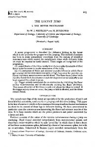
The geometry and biomechanical properties of the femur–tibia joint of the metathoracic leg play a crucial role in the energy storage for the jump (Fig.1). The tibia extensor muscle/apodeme is shown as a red line that attaches to the tibia (Fig.1a) whereas the tibia flexor
i
a
Kpe Kse
T B
b
f
Extensor muscle
Kpe T
h
g
Flexor muscle c
d
1
MN
2 Muscle
Kse
B
Scale
Adult locusts, Schistocerca americana L., were obtained from a breeding colony at Agnes Scott College, Decatur, GA, USA, kept caged in small groups at 27°C under a 12h:12h L:D cycle, and fed fresh organic lettuce and 2/1 mixture of fresh wheat germ and powdered milk. Individuals were taken from the cage to a videorecording room and placed on a jumping platform. The platform contained a heating element that could adjust the local temperature and was covered by very fine sandpaper to allow the locust a slipfree surface for jumping. A 25cm ⫻ 30cm yellow wooden target was placed 30cm from the platform, and jumps to the target were induced by either gentle touches of the abdomen by a hand-held wand or by raising the temperature of the platform. Animals were retrieved after the jump and returned to the platform for another attempt. Jumps were evoked at about 5min intervals; individuals were returned to their cage after 10 jumps. Locust jumps were recorded at 500framess–1 and a resolution of 512 pixels ⫻ 240 pixels by two Photron PIC R2 Fastcam video cameras (San Diego, CA, USA) with an exposure time of 0.5ms.
e
Tension
MATERIALS AND METHODS Animals
Femur
3 Vm
1061
5
4 Length
Tibia Fig.1. Model of the femur–tibia (FT) joint of the metathoracic leg. (a)Extensor apodeme attachment point on the tibia. (b)FT hinge joint and connection of semi-lunar process (SLP) spring. (c)Flexor apodeme attachment point on the tibia. (d)A more distal point on the tibia. (e)The SLP spring is attached between the femur and the tibia. (f)The SLP mass moves along the slider joint (g) oriented between the points b and g that is at an inclination of 36.9deg. (h)Heitler’s lump. The flexor muscle wraps over this lump to alter its orientation with respect to the tibia as the leg is moved. (i)The tendon lock is modeled as a spring located between points c and i (magenta line). It is only enabled when the tibia is fully flexed and flexor muscle has a tension greater than 0.15 N (Bennet-Clark, 1975; Heitler, 1974). The distance between a,b is 0.76mm, b,c is 1.64mm. The angle a,b,c is 144deg. and b,c,d is 143deg. (Heitler, 1974). The muscle model is shown for the flexor and extensor muscles. This consists of a spring (Kpe), in parallel with a tension generator (T), and a dashpot (B), in series with another spring (Kse). (1) The muscle is activated by firing of a motor neuron (MN). (2) This depolarizes the muscle membrane. (3) Changes in the membrane voltage (Vm) are converted to a tension value using a sigmoidal function. (4) The tension value is scaled based on the muscle length. (5) The scaled tension is applied to the muscle by the force generator to produce a contraction. Tibia extensor muscle/apodeme is shown as a red line, and the tibia flexor muscle/apodeme is shown in green.
muscle/apodeme is shown in green. It wraps over Heitler’s lump (Fig.1h) and attaches to the tibia (Fig.1c). The femur was connected to a small block of mass 1.6mg that represented the SLP (Fig.1f) (Bennet-Clark, 1975). A sliding prismatic joint connected the SLP to the femur (Fig.1g). During normal co-contraction, the distal end of the SLP (where the tibia attaches) moves 0.3mm ventrally and 0.4mm proximally (Burrows and Morris, 2001). The slider joint was oriented to allow the SLP mass to move in the same direction (Fig.1b–g). A spring attached the SLP mass to the femur and was oriented along the direction of movement of the slider joint (Fig.1e). The stiffness of the semi-lunar spring was calculated from a stress–strain curve obtained for the SLP (Bennet-Clark, 1975). Straining the process parallel to the extensor apodeme by 0.4mm required approximately 14.2N of force (Bennet-Clark, 1975). However, the SLP moves both proximally and ventrally, and this amount of proximal strain corresponds to 0.3mm of ventral strain, for 0.5mm of total strain. From this strain, we calculated the stiffness of the SLP as 28.4kNm–1. The semi-lunar spring constant was set to this value. The tibia was connected to the SLP mass by a hinge joint that allowed the tibia to rotate between 5deg. and 160deg. (Fig.1b). The femur–tibia hinge joint is connected to the SLP mass, so that during co-contraction and tibial extension, the hinge joint will move
THE JOURNAL OF EXPERIMENTAL BIOLOGY
1062 D. Cofer and others along the slider with the SLP mass to approximate the joint movement observed in the locust (Burrows and Morris, 2001). The distances and angles that define the relationships between the extensor attachment, femur–tibia hinge joint and flexor attachment were set to published measured values (the distance between a,b is 0.76mm and between b,c is 1.64mm. The angle a,b,c is 144deg. and the angle b,c,d is 143deg.) (Heitler, 1974). Muscle is represented in AnimatLab by a linear Hill muscle model (Hill, 1970; McMahon, 1984; Shadmehr and Wise, 2005a; Shadmehr and Wise, 2005b). Each muscle model consists of a serial spring (Kse) in series with the parallel combination of a parallel spring (Kpe), a dashpot (B) and a force actuator (T). Muscle model properties are determined by the resting muscle length, the spring and dashpot constants, the stimulus–tension curve and the length–tension curve. The stimulus–tension curve is a sigmoidal function that relates the force level of the actuator to muscle membrane depolarization. The length–tension curve is an inverse parabola that determines the percentage of actuator force that is applied at a given muscle length. Only two muscles for each of the rear legs are modeled in this simulation, the flexor tibiae and extensor tibiae. The maximum force that can be produced by the extensor is 15N, which is achieved upon depolarization after a latency of 300–800ms (Bennet-Clark, 1975). The serial spring constant of the extensor was calculated using the Young’s modulus of 18.9kNmm–2 found for the extensor apodeme by Bennet-Clark (Bennet-Clark, 1975). The average size of the apodeme test pieces was 3mm long ⫻ 0.25mm wide ⫻ 40mm thick, and so they have an area of 0.01mm2, and a length of 3mm. These values allowed us to calculate the spring constant as 63kNm–1 from Young’s modulus using the equation KYA/L, where Y is the modulus, A is the area and L is the length. In the absence of published measurements that would allow calculation of the parallel spring constant, we used a value of 20Nm–1 because it produced a small but noticeable tension when the extensor muscle was stretched. The damping coefficient of the extensor muscle was set by hand to 700Nsm–1 to produce a rise time to peak tension of approximately 400ms. The stimulus–tension curve and the response properties of the non-spiking neuron that represents the muscle membrane were configured to reproduce the twitch response of the extensor muscle to a single FETi spike at a femur–tibia angle of 90deg. (Heitler, 1988). The length–tension curve was also reproduced from muscle twitch values that were taken at various femur–tibia angles by stimulation of the muscle (Bennet-Clark, 1975). Stimulation of the extensor muscle produced twitch responses very similar to those recorded from extensor muscle in response to a FETi spike. The resulting length–tension curve of the extensor muscle reached the maximum at the fully flexed position and was reduced as the leg extended. Recordings from the flexor muscle showed that it produces a maximum tension of around 0.75N in response to tetanizing stimulation, and that it reached maximum tension 35–40ms after a latency of 15ms (Bennet-Clark, 1975). The following parameter values enabled the flexor muscle model to reproduce the recorded peak tension and tension time course; the serial spring constant, Kse, was 100Nm–1, the parallel spring constant Kpe was 20Nm–1 and the damping coefficient, B, was 10Nsm–1. The stimulus–tension curve was configured to produce the desired maximum tension. As with the extensor model, the flexor length–tension curve was near its maximum value when the leg was fully flexed and near its minimum value when the leg was extended. The tendon on the flexor muscle of the locust contains a pocket. When the tibia is fully flexed and the flexor has a tension greater
than 0.15N, this pocket is caught on Heitler’s lump, which helps keep the tendon locked in place (Bennet-Clark, 1975; Heitler, 1974). This tendon lock property plays an important role in the jump after co-contraction when the flexor muscle and motor neurons are being inhibited. The lock helps keep the tibia fully flexed even while the flexor tension is dropping. This prevents premature extension of the tibia and initiates the jump once the flexor tension drops below a threshold value for maintaining the lock. In the model, the tendon lock was represented by a spring that connects the flexor attachment to a point on the femur (Fig.1, magenta line between points c and i). The spring was disabled and produced no tension unless the tibia was fully flexed and the flexor tension was greater than 0.15N. Neural model
A conductance-based integrate-and-fire neuron model was used in this simulation. Neurons were modeled as single equipotential compartments, each characterized by a set of user-specifiable parameters, including membrane time-constant, size (i.e. input conductance), membrane voltage, current noise, initial spike threshold, spike-frequency accommodation, spike afterhyperpolarization conductance and calcium conductances with activation and inactivation variables (MacGregor and Lewis, 1977). The neural network used to generate both the kick and jump motor programs was designed to apply the correct motor signals in a sequence and duration that mimics the motor program seen during kicking in locusts (Heitler and Burrows, 1977a; Heitler and Burrows, 1977b). Initial flexion of the tibia begins when the nine fast flexor tibia motor neurons are stimulated to fire (Fig.2A, green FLTi neurons) (Burrows, 1995; Burrows, 1996). These neurons synapse onto the flexor muscle membrane (Fig.2F, light blue FM node) causing muscle depolarization and flexor muscle contraction. The fast extensor of the tibia motor neuron (Fig.2B, red FETi neuron) synapses onto the extensor muscle membrane (Fig.2E, light blue EM node) causing it to contract. A central excitatory synapse connects the FETi neuron to the fast flexor motor neurons (B to A) (Burrows, 1996; Heitler and Burrows, 1977b). There are also two inhibitory interneurons that are involved in triggering the jump. The multimodal ‘M’ interneuron (Fig.2C, gold M neuron) inhibits the excitatory flexor motor neurons, while the inhibitory flexor inhibitor motor neuron (Fig.2D, yellow FI neuron) synapses onto the flexor muscle and inhibits it directly (Burrows, 1995; Pearson et al., 1980). The tendon lock control node (Fig.2G, light blue) is responsible for enabling the tendon lock spring when the tibia is sufficiently flexed and the flexor has a tension above the lock threshold. The network that governs the right metathoracic leg is shown in Fig.2; an identical network governs the left metathoracic leg. Neurons were configured to reproduce the observed firing frequencies during the kick. Peak FETi neuron firing ranged between 60Hz and 100Hz (Heitler and Burrows, 1977a), while the FLTi neurons fired around 60Hz (Heitler and Burrows, 1977A). The central excitatory synapse connecting the FETi to the FLTi neurons was configured by reproducing an experiment in which the FETi was stimulated to fire at roughly 10Hz while the synaptic response of the FLTi was monitored (Heitler and Burrows, 1977b). The first FETi spike produced a 20mV EPSP (excitatory postsynaptic potential) in all of the FLTi motorneurons; the EPSPs decayed in approximately 100ms (Burrows, 1996; Heitler and Burrows, 1977b). Responses to subsequent spikes were reduced by synaptic depression in a manner similar to that observed experimentally (Heitler and Burrows, 1977b). All neurons had a random tonic noise of 0.3mV added to their membrane potentials at each time step. The pseudo-random number
THE JOURNAL OF EXPERIMENTAL BIOLOGY
Simulation of locust jump
A
D F
H
C B
G
E
generator that controlled the noise was initialized using a random seed value at the beginning of each simulation. This caused each simulation with a different seed to produce slightly different results because changes in the neuron voltages led to alterations in the timing of the motor program and the rise and fall times of the tension in each of the muscles. Procedures for simulation of experiments
During the kick simulations, the locust was suspended above the ground and rotated so that its ventral surface was uppermost, and pinned in place so it could not fall. All leg joints except the femur–tibia and tibia–tarsus joints of the metathoracic legs were locked to prevent rotation. The kick motor program caused the tibia to flex initially and then kick out at high speed. This allowed us to measure the movement of the SLP and tibial rotation. SLP torque relative to the extensor attachment was calculated by recording the coordinates of the femur–tibia joint, extensor attachment and the SLP force vector. These values were used to calculate the moment arm of the SLP force vector relative to the extensor attachment, and this was used to calculate the torque applied by the SLP. Kick velocity was measured as the peak velocity between the beginning of the kick and end of the kick when the tibia had fully rotated by 160deg. Kick duration was the time from the beginning of the kick until full rotation of the tibia. The same stimulus pattern that was used for kicks was applied to produce the motor pattern for the jump. Simulations of the locust jump began with the locust held 4.5cm above the ground, and then dropped to the ground. Initially, only the femur–tibia joints of the rear legs were free to rotate. All of the other joints were locked and unmoving, and the rear legs were held up in the air to allow the tibia to rotate freely without interference with the ground. Once the tibia was fully flexed, the metathoracic coax–femur joint was adjusted to fix the angle of the leg with respect to the ground and ensure a take-off angle of approximately 55deg. This angle was chosen because it produced jumps that minimized tumbling during take-off. The joints for all of the other legs remained locked throughout the jump motor program in order to maintain a stable and consistent posture, and the posture of the front legs was adjusted to fix the initial body pitch of the animal at 2deg. The locks on the joints of the front and middle legs were disabled when the jump was triggered. This allowed all the legs to move freely throughout the take-off and ballistic phase of the jump. The SLP was disabled for tests by locking the SLP sliding prismatic joint to prevent it from
1063
Fig.2. Neural network model to produce the kick and jump motor programs. Network shown is for the right leg. (A)Nine fast flexor tibia motor neurons (green FlTi). FlTis synapse onto the flexor muscle membrane (light blue FM). (B)A single fast extensor tibia motor neuron (red FETi). FETi synapses onto the extensor muscle membrane (light blue EM). (C)The multimodal interneuron (gold M) inhibits the FlTis. (D)The flexor inhibitor (yellow FI) inhibits the flexor muscle. (E)Depolarization of the extensor muscle membrane causes the extensor muscle to contract. (F)Depolarization of the flexor muscle membrane causes the flexor muscle to contract. (G)The tendon lock control node (light blue) controls when the tendon lock spring is enabled based on the rotation of the tibia and the tension in the flexor muscle. (H)When the jump is triggered the femur–tibia joint rotates rapidly to produce the kick or jump.
moving and by disabling the SLP spring to prevent it from generating tension. Extensor tension was controlled by varying the firing frequency of the FETi motor neurons. Predicted jump distance was calculated using the equation: d=
(
2 ⋅ E ⋅ sin 2 ⋅θ m⋅ g
)
,
(1)
where d is distance, E is energy, is the average take-off angle for all simulated jumps, m is the mass and g is gravity (Bennet-Clark, 1975). The power of the jump was calculated as the dot product of the force acting on the body during the jump impulse and the velocity of the body (Bennet-Clark, 1975). The energy of the jump was calculated by integrating the power curve over the time period of the impulse. The beginning of a jump or kick was always measured from when the tendon lock was disengaged. Jump duration was the time from the beginning until either the body or one of the rear legs first touched the ground. Jump distance was measured as the difference between the positions of the locust at the end and at the beginning of the jump. Jump impulse duration was the time from the beginning of the jump until one of the legs lost contact with the ground. Jump velocity and acceleration was the peak of those values obtained during the jump impulse. All data analysis was performed in Matlab (Matlab R2007a, Mathworks Inc., Natick, MA, USA), and statistical comparisons were made using its Anova1 one-way analysis of variance function. The influence of SLP flexion torque on the flexor muscle was determined by comparing the tension level at which the extensor muscle was able to overcome the tension in the flexor when the SLP spring was intact and when it was disabled. The extensor tension was set to 5N, and the tendon lock was disabled for both tests. The first test was performed with the SLP intact whereas in the second test the SLP spring was disabled. Once the extensor reached the 5N tension level the flexor was inhibited and its tension dropped until it reached a point where the extensor muscle was able to overcome it and extend the leg. RESULTS Motor program and jumping
The simulated motor program and patterns of muscle activity responsible for the kick are shown in Fig.3. The kick motor program began by stimulating the nine FlTi motorneurons on the right and left side (Fig.2) to fire at about 60Hz, which produced tension in
THE JOURNAL OF EXPERIMENTAL BIOLOGY
A
–60 0
B
–60 0
C
–60 0
D
–60
FT rot. Flexor Extensor Lock (deg.) (N) (N)
0
15 0
0 160 0 1 0 1.44
15
E
0 –0.8
F
0 1 0 160
G H
0 0
0.2
0.4
0.6
0.8 1.0 Time (s)
1.2
1.4
1.6
Fig.3. Neural output of the jump motor network. The nine flexor motor neurons were stimulated to fire (A) during the cocking phase, which increased tension in the flexor muscle (F) and rotated the tibia into a fully flexed position (H). The extensor motor neuron FETi (B) began firing to produce co-contraction and increase flexor frequency through the central excitatory synaptic connection from FETi to FLTi. The inhibitory interneurons M (C) and flexor inhibitor (FI) (D) then began firing once the extensor had reached the desired tension level (E). This caused the tension in the flexor (F) to fall below the tendon lock threshold (G), which disabled the tendon spring. The unopposed tension produced a rapid extension of the tibia (H). Each chart corresponds to the output from a labeled element from Fig.2.
the flexor muscles that caused the left and right tibiae to become fully flexed (Fig.3A,F). A train of current stimuli applied to the FETi motorneurons on both sides began the co-contraction phase (Fig.3B,E). Each current stimulus evoked a corresponding spike in FETi. In addition to driving the extensor muscle, the FETi excited the FlTis on the same side (Heitler, 1988) to enable the flexor muscle to keep the tibia flexed despite the mounting extensor tension. The kick was triggered by stimulation of the FI (Fig.3D) and M inhibitory neurons (Fig.3C) with an applied current for 80ms, which caused them to fire at approximately 200Hz. The FI neuron inhibited the flexor muscle, causing the flexor tension to decline rapidly. Simultaneously, the M neuron inhibited the FlTis to remove the drive on the flexor muscle. Rapid inhibition of the FlTis and the flexor muscle triggered the kick by reducing the flexor tension below the level needed to maintain the tendon lock (Fig.3F,G) (Heitler and Burrows, 1977a; Pearson et al., 1980). With the flexor tendon lock disabled, the tibia began to extend very rapidly, completing extension in 4ms, the same time course that was recorded with highspeed videography (Burrows and Morris, 2001). To test the hypothesis that the same neural circuitry and motor program could produce both the kick and the jump, we used the model of the kick circuit and motor program to evoke a simulated jump. An expanded view of the data for both the kick and jump are shown in Fig.4. Although the same motor program controlled both simulated behaviors, the unloaded leg extended in less than 5ms to produce the kick (Fig.4A) whereas the load imposed by the body caused the leg to extend much more gradually to produce the jump
Kick output
A
0.8
FT rot. Flexor Extensor Lock (deg.) (N) (N)
FT rot. Flexor Extensor FI (mV) (deg.) Lock (N) (N)
M cell (mV)
FETi (mV)
FITi (mV)
1064 D. Cofer and others
15
1.45
1.46
1.47
1.48
1.47
1.48
Jump output
B
0 0.8
0 160 0 1 0 1.44
1.45
1.46 Time (s)
Fig.4. Expanded view of jump or kick data. Kick data from Fig.3 is expanded and compared with data from a jump. The output of the motor program was the same for both the kick and the jump, and so was omitted here. Each chart shows the tension in the extensor and flexor muscle of the left metathoracic leg, the rotation of the femur–tibia (FT) joint and the status of the tendon lock. (A)To produce a kick, the tibia began to rotate very rapidly after the tendon lock was disabled, and completed full extension in 4.1ms. (B)The jump used the same motor program but the leg rotated more slowly because the tibia was loaded, and so reached its maximum value after 28.35ms. The colored plot lines have the same colors as the corresponding lines for plots of the same variables in Fig. 3.
(Fig.4B). Comparison of the simulated movements of the locust with a series of frames taken of a locust’s jump (S. americana) by a high-speed camera operating at 500framess–1 (see Materials and methods; Fig.5) shows that the simulation has captured the most salient features of the resulting jump behavior. In this, as in most of our recorded locust jumps, the animal’s legs left the ground at about 30ms after the start of the jump, and the head and thorax maintained their orientation during the 45ms that the animal remained in view (Fig.5, inset). Simulated locust jumps displayed most of these behaviors. The locust shown jumping in Fig.5 displays the same series of leg movements at the same times as the locust shown in the inset, although its body has begun to rotate forward by the final frame of the simulation. Published measurements of locust (Schistocerca gregaria) jump behavior (Table1) provide benchmarks with which to compare the model locust jump behavior. Model locust jumps were performed with randomly seeded noise added to the membrane potentials of all of the model neurons and muscles, while all of the other model parameters were kept constant. Randomly seeded membrane potential noise ensured that the locust behaved slightly differently for each jump simulated under a given set of parameter values due solely to the randomness in the neurons and their effect on the biomechanics. This provided a method to measure the variance of the behavior when all of the other initial conditions were identical. By varying the FETi firing frequency extensor tension it was possible to encompass the entire range of behavioral data that was observed in the live animals. Several indicators of jump performance were
THE JOURNAL OF EXPERIMENTAL BIOLOGY
Simulation of locust jump
0 ms
15 ms
0 ms
22 ms
Fig.5. Screenshots of the simulated and real locust jumping. Images of a real locust jump are in the insets. The simulated locust produces a jump very similar to those recorded from live locusts. Live locust images are sequential frames taken using a high-speed camera at 500framess–1.
18 ms
14 ms
28 ms
1065
19 ms
38 ms
26 ms
23 ms
38 ms
obtained and compared with the published benchmark values for live locusts (Table1), and were found to be essentially the same. FETi frequencies between 44Hz and 100Hz produced extensor tensions from 9.4N to 15N that led to jumps between 46cm and 120cm long (Table1; Fig.6A circles, R20.96). The simulations most closely matched the live data when the FETi frequency was set to 50Hz, which evoked extensor tensions of 12N and jumps 64cm long. Energy for the jump also varied linearly and provided a very good match to the predicted distance for that energy level and take-off angle (Fig.6B, R20.98). These similarities demonstrate that the jump performance of the locust using the kick motor program closely matched that of the live locusts. Role of the SLP
The contribution of the SLP to the locust jump was analyzed by comparing jumps made with the SLP intact with jumps made with it disabled. Without the SLP, the jump distance remained proportional to extensor tension but the slope of the regression line was reduced by 40% and the projected X-intercept (the minimal extensor tension needed to produce a jump) was greater (Fig.6A squares, R20.95). The difference in slope indicates that the SLP increases the effect of a change in extensor tension on the distance jumped. The difference in X-intercept provides a measurement of how energy storage by the SLP reduces the minimal extensor tension needed to make a jump. The difference between the two regression lines was used to determine the contribution of the SLP to jump distance for different extensor tensions. When the SLP was disabled
the jump distance was reduced by 45% at 15N and by 55% at 10N. The peak power of the jump impulse when the SLP was intact was significantly higher than when the SLP was disabled (1.94±0.05mW with, 1.10±0.04mW without, P